DALI LED Driver Control System Using Raspberry Pi3: Design & Implementation | Môn Hệ thống nhúng trong công nghiệp - Đại học Sư phạm Kỹ thuật Thành phố Hồ Chí Minh
Public lighting installations are important source of energy consumption. Every commercial and residential building consumes a great deal of electrical energy through lighting systems. Tài liệu được sưu tầm gồm 23 trang, giúp bạn ôn tập tốt hơn. Mời các bạn đón xem.
Môn: Hệ thống nhúng trong công nghiệp 10 tài liệu
Trường: Trường Đại học Sư phạm Kỹ thuật Thành phố Hồ Chí Minh 4.4 K tài liệu
Tác giả:


Preview text:
lOMoAR cPSD| 58702377
DALI LED Driver Control System for Lighting
Operations Based on Raspberry Pi and Kernel Modules George K. Adam
Department of Digital Systems, University of Thessaly, 41110 Larisa, Greece; gadam@uth.gr
Received: 26 August 2019; Accepted: 10 September 2019; Published: 12 September 2019
Abstract: Light emitting diodes (LEDs) as an efficient low-consumption lighting technology are
being used increasingly in many applications. The move to LED lighting is also changing the way
the lighting control systems are designed. Currently, most electronic ballasts and other digital
lighting devices implement the Digital Addressable Lighting Interface (DALI) standard. This paper
presents a low-cost, low-power effective DALI LED driver controller, based on open-source
Raspberry Pi3 microcontroller prototyping platform. The control software is developed as a Linux
kernel module under UBUNTU 18.04.2 LTS patched with PREEMPT_RT (Preemptive Real-time)
for real-time processing. This dynamically loaded kernel module performs all the processing,
communication and control operations of the Raspberry Pi3-based DALI controller with the DALI
LED driver and LED luminaire. Software applications written in C and Python were developed for
performance testing purposes. The experimental results showed that the proposed system could
efficiently and effectively manage DALI LED drivers and perform lighting operations (e.g.
dimming). The system can be used for a variety of purposes from personal lighting control needs
and experimental research in control of electronic ballasts and other control gears, devices and
sensors, to advanced requirements in professional buildings, including energy management,
lighting maintenance and usage.
Keywords: Raspberry Pi3; microcontroller; control system; kernel module; DALI protocol 1. Introduction
Public lighting installations are important source of energy consumption. Every commercial and
residential building consumes a great deal of electrical energy through lighting systems [1 3].
Installations on domestic premises, offices, or other private premises are also considered to be
important [4]. In this direction, the work of Li et al. [5] provides a means to select appropriate
photoelectric lighting control systems based on the energy savings. Several control strategies have
been proposed for energy efficient office lighting systems design [6,7]. Therefore smart lighting
systems should be used for energy management to reduce consumption. Towards this direction,
light emitting diodes (LEDs) have proven to be a promising technology since they combine high
efficiency, environmental benefits, high reliability and long lifetimes [8]. LEDs are being used
increasingly as low-consumption light sources in many applications [9]. The move to LED lighting
is also changing the way the lighting control systems are designed [10 12]. LEDs are close to being
monochromatic light sources (half-bandwidths of 20 30 nm) and they provide roughly linear light
output in response to stimulating control signal. The response time of LED chips is very fast (in the order of nanoseconds) [13].
Lighting control systems use a variety of communication protocols such as DMX (Digital
Multiplex Signal), RDM (Remote Device Management), KNX (Konnex Networks) and Digital
Addressable Lighting Interface (DALI) to link control devices to lighting device drivers and
luminaires [14]. DALI is such a widely-adopted protocol. DALI is a standard communication protocol
Electronics 2019, 8, 1021; doi:10.3390/electronics8091021
www.mdpi.com/journal/electronics
for lighting control. The interface and protocol are defined by the International Electrotechnical
Commission as an IEC 60929/EN 60929 standard [15], and were modified by IEC 62386 standard [16].
DALI-2 refers to the latest version of the DALI protocol. For DALI-2 the IEC 62386 standard was
reconstructed in late 2014 to include many improvements and additional new commands and
features. Most current digital ballasts and other electronic lighting devices (e.g. power switches,
sensors and detectors, transformers, etc.), implement the DALI protocol. This is due to its simplicity
on wiring and communication needs, based basically on two wires for the transmission of the control
signals for commissioning or other maintenance purposes.
Microcontrollers are the heart of any control system, and as such they play a crucial role in
commercial and non-commercial lighting systems. Microcontrollers offer the advantages of low-cost,
low-power and rapid application development and implementation. The increasing integration of
microcontrollers, particularly with PWM (Pulse Width Modulation) control circuits, high resolution
timers and other control blocks, allow them to control the lighting systems directly and provide more
efficient control at lower costs [17,18]. Microcontrollers provide a flexible control platform for
handling a wide range of lighting systems found in offices and domestic premises.
Today, microcontroller boards that integrate on a system-on-a-chip (SoC) 32-bit or 64-bit
microprocessors have the ability to execute powerful instructions in a single clock cycle, and achieve
high throughputs. As such, there is an increasing development, and applications of such systems,
towards low-cost, high-performance and digital control of electronic ballasts. Many companies,
including Texas Instruments, STMicroelectronics, NXP Semiconductors and Microchip, produce
such microcontrollers optimized for lighting control. Such systems, typically integrate analog
circuitry combined with digital modules under firmware control [19,20]. They also integrate
peripherals such as LCD and touchscreen controllers and networking capabilities to high end devices
such as smart phones. Today the Internet-of-Things (IoT) revolution has shaped a new application
domain where computing in technological applications is typically performed on low-power RISC
(Reduced Instruction Set Computer) architectures and general-purpose microprocessors. Raspberry
Pi is such an intelligent microcontroller that has been employed in many scientific applications
including light control [21 24].
This paper presents the results of research on the implementation of a DALI LED driver control
system, based on a Raspberry Pi3 Model B (referred from now on as RPi3) microcontroller board.
The choice of RPi3 is based on the fact that it is being extensively used for embedded low-powered
control applications, due to its computing power in regard to its price, its ease of use with peripheral
equipment and low-energy consumption [25]. In addition, research shows that such a system is
capable to support adequate timing for most measurement purposes [26]. The system runs UBUNTU
patched with PREEMPT_RT [27] for real-time processing. The main control software is developed as
a Linux kernel module. As such, it saves some RAM space since it can be compressed in the same go
as the main Linux kernel; that is important in embedded systems with little storage. This module
performs all the processing and communication operations of the RPi3 DALI controller with the
DALI ballast (DALI LED driver) and LED luminaire, and generates appropriately Manchester
encoded control signals for digital lighting operations. It interprets user data and sends to the DALI
ballast appropriate DALI commands for commissioning and lighting control operations (e.g. lights
on/off and dimming) and other viewing or modification purposes (e.g. maintenance tasks and energy status info).
The novelty of this work is based on the fact that it uses an inexpensive and widely used in
many other research and educational purposes ARM (Advanced RISC Machine) development board
such as Raspberry Pi, to implement the DALI lighting control protocol architecture, based on open-
source dynamic loadable kernel modules, that save RAM storage space, usually limited in embedded
devices. Additionally, the control system is enhanced with hard real-time capabilities, based on the
PREEMPT_RT real-time patch, installed and configured appropriately, in order to support future
advanced timing requirements in control of electronic ballasts and other control gears, devices and
sensors, which may have more strict timing requirements in transmission of the control signals.
Some of the key features and advantages specific to this research work, compared to other
related work, examined in detail in the section that follows, are the following:
• The hardware implementation approach was designed to be easily set up, based on ARM
Raspberry Pi development board, for fast construction and experimental testing purposes.
• The DALI control software is based on dynamic loadable kernel modules that provide flexibility
to the overall DALI driver control system, and save RAM storage space, usually limited in embedded IoT devices.
• The control system is enhanced with hard real-time capabilities, based on PREEMPT_RT
realtime patch, therefore is capable to support future deterministic timing requirements in
control of electronic ballasts and other control gears.
• The Raspberry Pi3 microcontroller is easily reprogrammable and reconfigurable, supports
various programming environments and therefore, DALI lighting control applications making
use of the open-source developed DALI kernel module could be written in various
programming languages, particularly in educational and research environments with limited
budgets or technical skills, and limited resources.
This paper is structured as follows: Section 2 describes previous related work; Section 3
describes the materials, design methodology and goals, of the proposed design architecture; Section
4 presents the implementation of the proposed system architecture; Section 5 describes the software
modules developed for DALI communication and control; Section 6 presents the experimental
results and provides a brief discussion of the experimentations carried out and system s overall
performance; and Section 7 draws conclusions. 2. Related Work
Reviewing the literature, many works deal with smart lighting control [28 30]. However, most
of these works are based on powerful PCs and servers. For example, the work of Wang et al. [31]
presents a system for a digitally-controlled ballast for ultraviolet lamps based on a ZigBee DALI
bridge module that connects to a PC. Such systems, although powerful, do not have the flexibility
and variability of applications provided by embedded microcontroller-based control architectures
like the system proposed in this research. In addition, power requirements and cost is quite high.
Embedded systems based on microcontrollers are widely used in real world commercial,
educational and research applications. In particular, applications featuring ARM-based
microcontroller boards (e.g. Texas Instruments boards, NXP Semiconductors boards, Beagle Board,
Raspberry Pi, etc.) with Linux as an embedded operating system are quite common and offer
appropriate computing performance. The embedded microcontroller technology could be used for
various lighting control purposes in various fields, in building and civil engineering [32], in vision
research [33,34], in agriculture [35], in smart home [36], etc. In recent years, interesting applications
in lighting control and energy-saving are implemented based on Arduino micro-controller, such as
the work of Yin et al. [37], based on Arduino Mega 2560. In this work, the authors present a novel
energy-saving control strategy applied to minimization of the light-energy consumption, by
separately manipulating the brightness of multiple lighting sources, and realizing the desired
lighting level. Arduino is not as powerful as Raspberry Pi, but is very suitable for such control
application purposes. However, the developed lighting control system does not implement the DALI communication protocol.
In our previous research work [38], we have investigated lighting control issues (e.g. dimming)
in educational laboratories based on a BeagleBone Black microcontroller. In current research, the
proposed system is implemented in a more versatile, cheaper and powerful microcontroller, the
Raspberry Pi3, enhanced with real-time capabilities, and a Python-based graphical user interface for
user friendly application control.
Lighting control systems, sensing and actuation devices, which are automatically controlled
from both embedded computing devices (e.g. Raspberry Pi) and remote control units such as smart
phones have become quite common [39 41]. The work of Leccese et al. [42] presents such a control
system for full control of street lighting, based on a Raspberry Pi and a ZigBee module. This is an
interesting research work, however the authors do not implement the DALI protocol in the control
of the street lighting. The same applies for the work of Bannamas et al. [43], where the authors
present a lighting energy management system based on Raspberry Pi, but with no DALI protocol implementation.
DALI-based lighting control systems are commonly preferred due to their advantages on
performing digital lighting control operations and other management tasks (e.g. energy monitoring)
[44,45]. However, most of these works are based on microprocessors other than ARM or Raspberry
Pi based microcontrollers [46 49]. For example, the work of Liang et al. [50] presents a LED DALI
dimming control system based on PIC 16F684 micro-controller. This micro-controller is suitable for
this specific application, however it falls quite below the requirements for future experimental
research, and the capabilities of the 64-bit ARMv8 multi-core CPU-based Raspberry Pi
microcontroller, utilised in the system proposed in this current research. The work of Bellido-
Outeiriæo et al. [51] presents a lighting control system based on TI CC2530OEM control board (CPU
8051) powered from mains (230 VAC) for managing public lighting networks. The control board,
although efficient, is not easily reconfigurable, neither versatile in use, having quite a high
implementation cost, and a power requirement from mains power supply, which makes it restrictive
for remote installations and applications. Another work of Archana et al. [52] presents a spot
luminaire control unit based on a STM32F302 MCU. The implementation is focused and limited to
the control of a specific motorized and movable LED luminaire, while the DALI control software is
implemented in C as a user-space application, not favorable for limited in memory space embedded applications.
ARM-based board computers such as RPI3 provide more computing power, and Linux as an
embedded operating system, at a low price. In general, lighting control systems based on Raspberry
Pi microcontrollers, and particularly applied in LED control, are numerous [53 59], but none of them
implements the DALI protocol. There is still very limited research work that implements the DALI
protocol based on Raspberry Pi, and that is dedicated to the control of DALI ballasts, for research or
commercial purposes. Recently, such a work of Sinha et al. [60] investigated the communication
mechanism of a DALI network of a group of lights with a Raspberry Pi over MQTT (Message
Queuing Telemetry Transport) protocol, used for energy usage optimization purposes.
Compared to existing work, this paper focuses on the development of an embedded DALI
lighting control system e.g. for dimming purposes, based on a Raspberry Pi3 microcontroller with
real-time capabilities due to PREEMPT_RT patch, and dynamically loadable kernel modules as the DALI control software.
3. Materials and Methods 3.1. The DALI Protocol
The standardization of the signals for the controllable electronic ballasts is necessary for
obtaining interchangeability between controllable ballasts. The Digitally Addressable Lighting
Interface (DALI) has emerged as a standard to address growing power issues, mostly for commercial
and industrial purposes. The DALI standard was defined in the IEC 60929 standard (described in
Annex E) for fluorescent lamp ballasts (part 201), published by the International Electrotechnical
Commission. Subsequently, it was updated to the new standard IEC 62386, to include other
electronic lighting equipment, such as LED modules (part 207, IEC 62386-207:2018) [61]. DALI-2 is
the latest version of the DALI protocol which includes control devices (part 103). All new parts of
IEC 62386 are aligned with DALI-2.
DALI consists of a single set of control wires that form a low-voltage two-wire serial bus. This
pair of wires form the bus for communication to all devices on a single DALI network. A DALI
network consists of a controller and one or more DALI lighting devices (up to 64 devices with each
ballast having its own unique stored address).
The DALI controller sends 16-bit Manchester encoded (bi-phase) data packets, and the ballast
can respond with an 8-bit Manchester encoded data packet. Data is transferred between controller
and devices by means of an asynchronous, half-duplex, serial protocol over a two-wire differential
bus, with a fixed data transfer rate of 1200 bit/s. A DALI control interface voltage between 9.5 V and
22.5 V is considered a physical high signal (typical 16 V), whereas a voltage in the – 6.5 V interval
(typical 0 V) is taken as a physical low signal. In general, the interface voltage is high if there is no
communication (idle state). The current allowed to run through a network is limited to 250 mA
with a maximum consumption of 2 mA per ballast.
DALI protocol is based upon the master-slave principle. The master (DALI controller) sends
messages (forward frames) to any slave device (DALI ballast) in the system, while any slave may
respond with messages (backward frames) with maintenance and energy information such as the
status of the ballast and luminaries.
As shown in Figure 1, a DALI message structure is made up of an address and a command. The
address corresponds to one of the ballasts in the loop, and the command tells that particular ballast
what to do. All modules execute commands with broadcast addresses. A frame sent by the master,
called a forward frame, consists of 19 bits (a start bit, address byte, command byte and two stop bits),
while a backward frame sent by the slave is an 11 bits frame (a start bit, data byte and two stop bits).
Figure 1. Digital Addressable Lighting Interface (DALI) protocol two-way communication message
structure (forward & backward frames).
DALI-based systems provide more functionality than being just typical switching and dimming
devices, which justified its selection in this current research. DALI systems are very flexible and
highly functional. They allow individual and grouped control of lighting, and can be scheduled
when they are needed, and so provide efficient energy and cost savings. Keeping the application cost
low is essential for this research work too. It is possible to extend such systems by adding other DALI
controlled equipment e.g., photocells, sensors, touch screens, etc. This is quite attractive feature for
future experimental research work in control of electronic ballasts and other control gears, devices
and sensors. DALI lighting systems, can be easily and efficiently controlled by computing devices,
as this research documents too, and provide valuable information about their status and fault
conditions. Finally, DALI is an international standard, widely used in many compatible devices and
ballasts produced by different manufacturers. 3.2. Design Overview 3.2.1. Essential Requirements
A typical DALI lighting control architecture includes a microcontroller that acts as the master
controller for sending lighting control instructions and receiving status information to/from the
DALI ballast unit (slave) that drives the lamp/LED luminaire. The software control architecture
should comply with the DALI communication protocol specifications and be capable to control most
of the DALI ballast driver s operation aspects. Additionally, the system architecture must be flexible
and customizable, to such extend so that to be enhanced and modified according to various user-
derived system specifications and requirements. 3.2.2. Design Goals
The aim is to implement a low-cost and low-power open-source embedded control system for
the communication and control of standard DALI ballast drivers, based on commonly available
openarchitecture microcontrollers such as RPi3, and being capable to adapt easily into any lighting control application needs.
A summary of the requirements the final system must fulfil are the following:
• Low-cost and low-power embedded microcontroller-based control architecture.
• Easily reprogrammable and reconfigurable according to the user lighting needs.
• Operation system with support on hard real-time functionality.
• Integration flexibility within building control panels or with other lighting control systems.
• Ability to wirelessly connect for control and monitoring purposes using standard connection
protocols (e.g. Wi-Fi, Bluetooth).
• Capable to support experimental scientific research in control of electronic ballasts and other
control gears, devices and sensors.
The RPi3 microcontroller presents such a low-cost sophisticated digital control device with
higher level of computing capabilities among other microcontroller boards, and eventually
comparable to commercial control panels. Table 1 shows some principal characteristics of commonly
used low-cost but powerful microcontroller boards for research and educational purposes.
Table 1. Commonly used low-cost single board microcontrollers. Arduino Uno Raspberry Pi3 BeagleBone Black R3 ARM Cortex-A53 ARM Cortex-A8 ATmega328P CPU (64-bit) (32-bit) (8-bit AVR) Memory 1 GB LPDDR2 512 MB DDR3 32 KB flash Operating Linux Linux Custom System 6 analog, 7 analog, GPIOs 40 digital 14 digital (6 65 digital (3.3 V) PWM) 10/100 Mbps Ethernet, Network 10/100 Mbps Ethernet via shields Bluetooth, Wi-Fi 4 USB hosts, 1 1 USB host/client, 1 USB Peripherals 1 USB, 1 UART micro-USB power host, 4 UART Power Draw 1.34 A, 5 V 250 mA, 5 V 50 mA, 3.3 V Average Price 35 49 35
Digital ballasts control devices typically present a higher component cost largely due to power
supply, or router requirements, and the need for dimmer modules, or control panels, in larger
installations. The RPi3 is being extensively used for embedded applications. Although primarily is
designed to function as a general processing computer, it shares many characteristics of an embedded system [62].
In the proposed design architecture, the RPi3 will act as the master digital lighting controller of
the DALI devices in the network, capable to provide several control functions, including ballast
address, ballast control, LED/ballast status, etc. It will facilitate the DALI control bus two-way
communication protocol, having higher degree of communication and automation flexibility. The
RPi3 microcontroller can be easily reprogrammed and reconfigured according to the user lighting
needs, or for integration with other lighting control systems. The overall system could be used for a
variety of purposes from private lighting control needs management (e.g. dimming control) and
experimentation in small premises (e.g. flats, offices), to advanced requirements in professional
buildings, including lighting usage and maintenance. 3.2.3. Concepts and Issues
The overall system development should be based upon a microcontroller and operating system
capable to support the DALI communication mechanism in real time. DALI protocol operates at 1200
Hz that is a low frequency within the range of microcontrollers frequencies and communication
mechanisms. Data transfer rate is 1200 bits per second with an acceptable range of – 10% (timing bit
tolerance). Therefore one bit is transferred approximately every 833.333 μs. The DALI driver power
supply needs fast response time and efficient current limiting (max 250 mA). Response time of the
current limiter circuit is <10 μs. The response times (falling and rising slopes at low and high levels
respectively) of the received and transmitted data signals at the ballast DALI (digital) terminals,
should be in between 10 μs and 100 μs. Such signal levels are considered to be reasonable for reliable
operation of the DALI ballast.
In the proposed system, the RPi3 microcontroller is running UBUNTU 18.04.2 LTS (kernel
version 4.15.0.1041-raspi2 #44 Ubuntu SMP PREEMPT armv7l) and supports real-time interface
circuitry with peripherals (e.g., sensors and actuators). UBUNTU Linux kernel is a low-latency
preemptible kernel by default, capable to satisfy soft real-time requirements of control applications.
Thus, the default scheduler cannot provide fixed and predictable latency required e.g. for real-time
data sampling. Due to future application work intension, PREEMPT_RT real-time patch was
installed additionally, to provide OS with deterministic scheduling and hard real-time capabilities
with a fully preemptible kernel. This makes the porting of a non-time-predictable OS to a real-time
environment an interesting alternative. This will ensure future experimental research work in control
of electronic ballasts and other control gears, devices and sensors, which have more strict timing
requirements in transmission of the signals (e.g. in vision research, and fluorescence microscopy).
3.3. System Architecture
The design and implementation flow of the proposed system development involves the initial
specification of modules and units, their analysis, the actual programming and configuration steps,
and finally real-time experimentations of the applied system for performance validation purposes.
The proposed control system consists of all the essential modules for DALI ballast
communication and control, based on RPi3 microcontroller board that integrates an ARMv8
CortexA53 quad core processor unit within a Broadcom BCM2837 SoC [63]. The microcontroller has
the ability to wirelessly connect to other devices for data transfer using standard connection
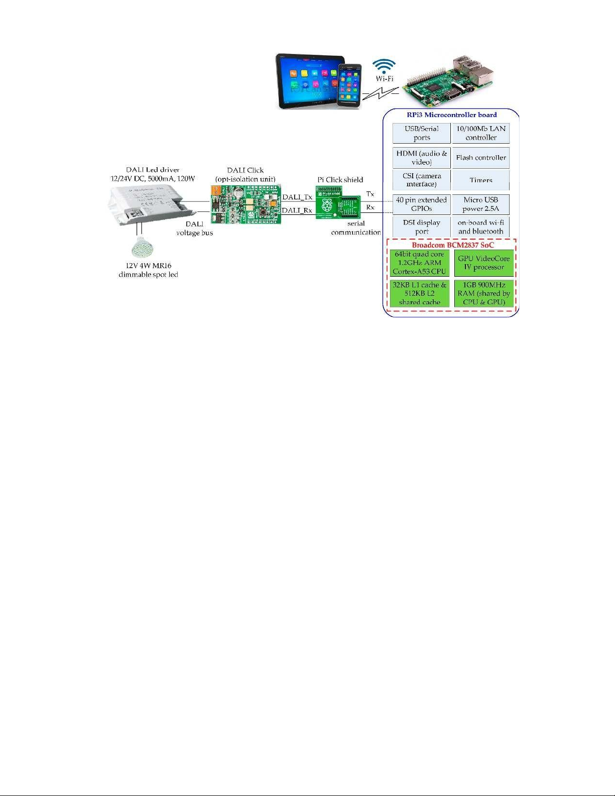
protocols (Wi-Fi, Bluetooth). The overall system is tested upon the control of a DALI LED driver
device (12/24 V DC, 5000 mA, 120 W). The DALI interface bus uses voltage levels to represent the
high logic level between 11.5 V and 22.5 V. Therefore, the control part of the DALI voltage bus needs
to be isolated. This is achieved through an opto-isolation unit (DALI Click) that acts as an interface
between the ballast and the microcontroller. A dimmable 12 V 4 W MR16 spot LED is connected to
the DALI LED driver. All the system s components, except for the DALI ballast, need a low-power supply voltage of 3.3 V DC.
The networking capabilities of the RPi3 such Ethernet, Bluetooth and Wi-Fi allow wireless
communication with mobile phones running for example on Android and iOS/iPhone. Therefore, a
remote-control system based on such intelligent device (e.g. tablet, smart phone) could be applied
for monitoring and control of the RPi3-based DALI control system for luminaire management and
maintenance issues. A general view of the proposed system is given in Figure 2.
Figure 2. Raspberry Pi3 Model B (RPi3)-based DALI controller block diagram.
The kernel-based control software module developed within the microcontroller manages the
DALI communication and messages conversion to/from the Manchester code. The microcontroller
converts user lighting commissioning commands into acceptable formats (that conform to IEC 60929
and IEC 62386 DALI protocol standards), and routes them over a two-wire voltage interface as
appropriate signals to the ballast. On physical level the communication is implemented with GPIO
(General-Purpose Input/Output) interfacing. An add-on board of optocouplers provides an isolation
circuit for connecting to DALI ballast that drives a dimmable spot LED. 4. Implementation 4.1. Hardware
The development of the experimental testbed platform is based on Raspberry Pi3 Model B
microcontroller board, a Pi click shield, a DALI Click opto-isolation unit, a DALI LED driver and a
dimmable 12 V 4 W MR16 spot LED luminaire. 4.1.1. Microcontroller
RPi3 is a low-cost, low-power, portable and stand-alone single board computer. RPi3 can be
either powered by the USB interface or with an external power supply or a battery. RPi3 integrates
a SoC based on Broadcom BCM2837, which includes an ARMv8 Cortex-A53 quad core processor at
1.2 GHz, and an 1 GB LPDDR2 (900 MHz) memory module that facilitates data exchange between
the processor and other peripheral units. Other chips on board support interface circuitry with real-
time peripherals (e.g., sensors and actuators). The CPU supports ARMv8-A architecture and is
capable of supporting 32-bit and 64-bit instruction sets. There are a number of GNU/Linux
distributions for the Raspberry Pi, one of which is UBUNTU 18.04.2 LTS.
4.1.2. DALI Click Opto-Isolation Unit
The microcontrollers do not usually have an integrated peripheral that communicates with
DALI ballast drivers using the DALI protocol. Therefore, an additional opto-isolation unit is
integrated to enable optically-isolated communication of the RPi3 microcontroller with the DALI
ballast driver. Dali Click is a compact add-on board (by MikroElektronika) and safe solution for
connecting to DALI ballasts drivers. The board communicates with the RPi microcontroller via four
mikroBUS lines (RST, CS, PWM and INT) through a Pi click shield. It transfers data between the
microcontroller and DALI devices over a two-wire differential bus by means of asynchronous,
halfduplex, serial protocol. It features two optocouplers that provide an isolated DALI
communication circuit interface. The board is powered by the RPi microcontroller with 3.3 V power supply.
The DALI Click adapting level circuit board is utilized as a CMOS-DALI interface with low
power supply (3.3 V). This is because a DALI control interface voltage between 9.5 V and 22.5 V is
considered a physical high signal, whereas a voltage in the –6.5V interval is taken as a physical low
signal. Therefore, as the microcontroller digital outputs are CMOS (0 3.3 V) it is necessary to use an
adapting level circuit to convert the 3.3 V to the corresponding levels of the control signals.
4.1.3. DALI LED Driver and Spot LED Luminaire
The target ballast device used is a DALI LED driver with input voltage 12/24 V DC, output
voltage 12/24 V DC, output current (max) 5000 mA, LED min load 1W and max power 120 W. The
electronic ballast provides the 12 V 4 W MR16 dimmable spot LED with a constant voltage (CV
mode). LED luminaries are preferred since they have quick switching times, without the need for
preheating, high lighting efficiency, and low power consumption. Table 2 shows their characteristics.
Table 2. DALI Light emitting diode (LED) driver and LED parameters. Parameter DALI LED Driver Parameter Spot LED Input voltage: DC 12 24 V Voltage: 12 V Output voltage: DC 12 24 V Colour LED: 2700 K warm white Output current: 5000 mA Dimmable: yes Dimming frequency: 50 Hz Luminous flux: 400 lm Max output power: 120 W Power: 4 W Min load: 1 W Efficiency: 100 lm/w
4.2. Microcontroller and DALI Click Communication
A Pi click shield is utilized as an extension to RPi3 having a mikroBUS (an add-on board
standard) host socket compatible with DALI Click boards. The mikroBUS socket comprises a pair of
female headers with a pinout configuration that consists of three groups of communications pins
(SPI, UART and I2C), six additional pins (PWM, Interrupt, Analog input, Reset and Cip select), and
two power groups (3.3 V and 5 V). Four mikroBUS lines RST, CS, PWM and INT on Pi click shield
are used to establish the communication between the RPi3 and Dali Click board. RPI s GPIO14 pin
out, connected to RST pin in Pi click shield, is used to transmit commands (DALI_TX) to the DALI
LED driver. On the other hand, RPI s GPIO15 pin in, connected to INT pin in Pi click shield, is used
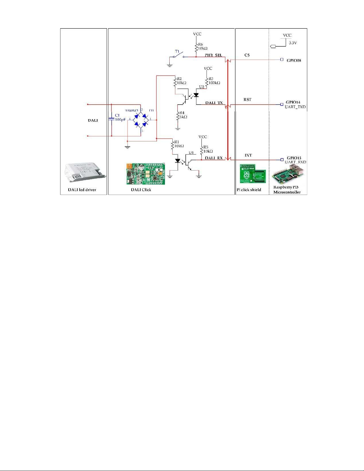
to receive feedback (DALI_RX) from the DALI LED driver. Figure 3 shows the connections between
DALI LED driver, Dali Click, Pi click and Raspberry Pi3 microcontroller.
Figure 3. DALI interface and system connections.
The DALI Click board is optically isolated from the DALI LED driver and communicates with
the driver via a two-wire connection. The RPi3 microcontroller communicates with Dali Click
basically via two lines (DALI_TX, DALI_RX). The signals used are the transmit signal (DALI_TX) to
send commands (forward frames) to the DALI ballast and the receive signal (DALI_RX) to receive
ballast information (backward frames). The 3.3-V logic is translated at a higher voltage logic (16 V)
on the DALI bus. This provides the appropriate voltage e.g. for dimming control purposes. The
microcontroller can generate different voltage levels to control the communication and transfer the data for dimming purposes.
When a forward frame command is executed optocoupler U2 enables the transmission from the
microcontroller to the DALI LED driver. The driver may react only when a query command is
executed that requires a feedback. Optocoupler U1 deals with the reception of the backward frame
when such a query message has been sent. A high level signal in DALI turns into low level in the
microcontroller digital input DALI_RX. When DALI_TX is put in high (high level signal) diode in
U2 is not biased and its phototransistor is open, giving a high level. When DALI_TX is put in low
(low level signal) the LED is biased and the transistor is closed. The control software developed in
the microcontroller is responsible for inverting the signals values (due to the optocouplers signals
level inversion) and perform the Manchester encoding/decoding.
5. DALI Communication and Control Software Modules
5.1. Operating System and Kernel Modules
The embedded computer operating system is a customized version of the UBUNTU Linux
operating system. UBUNTU 18.04 LTS is a Linux distribution also available for embedded IoT
devices such as RPis, PDAs, Microcontrollers boards and other IoT boards. An UBUNTU 18.04.2 LTS
image kernel version 4.15.0.1041-raspi2 #44 Ubuntu SMP PREEMPT was downloaded for RPi3, and
then compiled and installed (into microSD card). Some further configuration adjustments were also
made to the kernel configuration in order to support kernel modules manipulation. For this purpose,
kernel source files and make utilities were installed (apt install kernel-headers). In this way, kernel
modules could be compiled and inserted into kernel memory. The build process for external loadable
modules is fully integrated into the standard kernel build mechanism.
5.2. Ballast Communication and Control Modules
The DALI protocol communication is implemented as a kernel driver module loaded into the
kernel space. Further on, user space test applications have been developed to perform the actual
communication calls on module s functions to write and read from the DALI LED driver device. The
DALI kernel module and applications are developed in C (using Geany as the Integrated
Development Environment). A simple user interface (GUI) has been developed using the Tkinter
module in Python to provide a user friendly interaction with the DALI LED driver. All the
development process and compilations were executed on the microcontroller s board without any need for cross-compiling.
According to the DALI communication protocol a forward frame command consists of 19 bits
(1 start bit, 1 address byte, 1 data byte and 2 stop bits). The bits are sent most significant bit (MSB)
first. The packet is sent as a bi-phase Manchester encoded packet. The two stop bits have no phase
change. The Manchester code is a digital encoding format in which symbol 1 is represented by a
falling edge (high followed by low), and symbol 0 is represented by a rising edge (low followed by
high). The backward frame sent by the slave is an 11 bits frame with the same characteristics as the
forward frame (1 start bit, 1 data byte and 2 stop bits). DALI operation frequency is 1200 bps, which
means that 1 bit time is 1 s/1200 = 833,333 μs. Both the high and low pulses have equal width, which
is equal to half the bit period (Te = 416,666 μs).
The DALI kernel module implements the above specifications of the DALI communication
protocol, that is, it facilitates the communication of the RPi3 microcontroller with the DALI LED
driver. Once this module is successfully compiled and loaded into the kernel memory, afterwards
any application can make use of module s function calls to communicate with and control any DALI
LED device driver that comply with DALI protocol specifications.
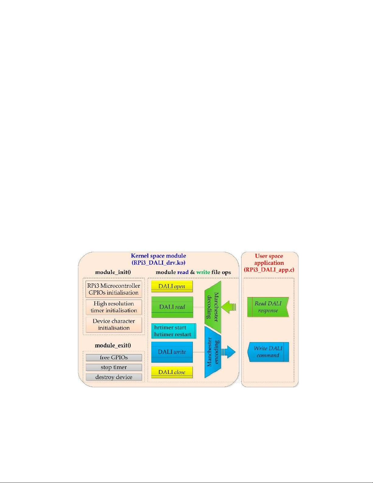
The overall functionality of the RPi3 DALI kernel driver module is shown in Figure 4.
Figure 4. DALI kernel driver module functionality.
Once the module s initialization process, and verification that all components are accessible, is
finished, the main tasks of this kernel module are two meaningful functions: RPi_dali_write and
RPi_dali_read; accordingly, for sending commands to the DALI LED driver and receiving responses
or information about the status of the devices. Function RPi_dali_read reads any data (ballast/LED
status information) that the DALI LED driver may send back as a response to an RPi_dali_write
command. Function RPi_dali_write encodes each command forward frame into Manchester coding
(where two states are sent for one bit) and fills in a forward frame list that consists of two stop bits
first, then a data byte, an address byte, and a start bit last. There is no phase change for the stop bits.
Finally, sends the command frame with most significant bit (MSB) first through the defined as an
output GPIO port to the DALI Click unit, which is connected to the DALI LED driver.
Since for every forward frame bit, two states are transmitted, and one bit transmit time is
approximately 833,333 μs, therefore, each bit state is transmitted every 416,666 μs (half bit period).
A high resolution timer is initiated to facilitate this transmission at these specific time intervals. A
highresolution timer is usually a requirement in real-time systems when a task needs to occur more
frequently than the 1 ms resolution offered with Linux. In our case, the UBUNTU kernel with
PREEMPT_RT patch produces timer interrupts at exact time intervals.
The algorithm that describes the basic functionality of these DALI kernel module file operations
(read and write) is shown as pseudocode in Algorithm 1:
Algorithm 1: DALI read and write kernel module file operations function RPi_dali_write
user_buf[2] ← address & data bytes of DALI command (forward frame list) pointer_to_kernel =
kmalloc(sizeof(kernel_buf), GFP_KERNEL) ← kernel allocated memory hrtimer_mode is
HRTIMER_MODE_REL ← time is interpreted as relative to the current time
half_bit_period_interval ← set to 416666 ns
copy_from_user(DALI_command, kernel_buf) ← copy address & data bytes from user space
application into kernel space memory
while no_of_iterations is below or equal to 2, do
dali_manchesterListAddVal(stopbit) ← send two stop bits with no phase change
dali_manchesterListAddByte (databyte) ← send DALI command data byte
dali_manchesterListAddByte (addressbyte) ← send DALI command address byte
dali_manchesterListAddVal(startbit) ← send start bit of logical 1
hrtimer_start high_res_timer ← starts high res timer (time interval equal to half bit period)
end function RPi_dali_write function RPi_dali_read user_buf[1] ← data byte from DALI
command response (backward frame list) copy_to_user(DALI_response_command, user_buf) ←
copy data byte from kernel space into user space application memory
end function RPi_dali_read
The experimental software RPi3 DALI kernel module, Python interface and C application source
code developed in this research are available as an open-source project at GitHub public repository
https://github.com/gadam2018/RPi3-DALI.
6. Experimental Results
The experiments were carried out in our Digital Systems lab capable to support the investigation
of the overall system s functionality and reliability of operation. Figure 5a,b shows an image of the
system implemented consisting of the RPi3 board with Pi Click, the DALI Click shield, the DALI
LED driver and the LED luminaire. (a) (b)
Figure 5. (a) RPi3, Pi Click and DALI Click shield; (b) the overall DALI LED Driver control system.
The system can drive any DALI LED ballast and luminaries. In particular, tests were
implemented for power dimming control of LED luminaries. The experimental results provided
evidence that the system performs correctly and enables appropriate communication and control
through the system s DALI bus interface.
The system due to its microcontroller and operating system capabilities allows any user
application to fully customize the commissioning features, such as dimming time and points, or
other maintenance issues, in contrast to fixed or limited function sets provided by some commercial products.
6.1. DALI Driver Module Application Experimental Results
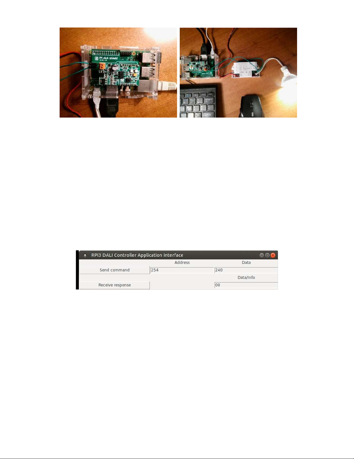
A simple graphic application (GUI), shown in Figure 6, has been developed
(RPi3_DALI_Controller_interface.py) using the Tkinter module in Python to provide a user friendly
interaction with the DALI ballast under control, through the C control application.
Figure 6. RPi3 DALI controller simple application interface.
This Python module uses ctypes foreign function library to communicate with the DALI kernel
driver by calling the C DALI_write and DALI_read functions, accordingly for Send command and
Receive response buttons press, and get/set the corresponding frame fields. For this purpose, these
C functions are defined within a shared library (libdali.so) generated as a shared object (gcc fPIC
shared o libdali.so DALI_C_functions.c) from a C functions file (DALI_C_functions.c). Partial code
of Python application interface and shared library is shown in Appendix A.
This simple GUI interface has been used for the transmission/reception of DALI frames. The
Send command transmits DALI commands into the ballast. Two bytes (defined in the address & data
text fields) properly encoded as a forward frame are sent to the ballast. The Receive response allows
the user to get information (backward frame) about the execution status of power control commands
(in case a response packet is expected) or query commands (answered with a Yes , No or 8-bit
information). The DALI kernel driver module is responsible for the appropriate encoding in
Manchester code format and implements the DALI communication protocol.
6.1.1. DALI Kernel Driver Module Dynamic Loading
The driver module (RPi_DALI_drv.c) is built by running (make) the Makefile shown in
Appendix B. This kernel driver module (RPi_DALI_drv.ko) is loaded into the kernel s memory (sudo
insmod). All modules loaded into the kernel are listed in system s modules file (cat /proc/modules)
and the devices directory (cat /proc/devices) as a character device. In order to make the kernel
module accessible by the application of any unprivileged user, the group associated with the kernel
module (e.g. root) is changed into that user s group (e.g. sudo chgrp ga /dev/RPi_DALI_drv). Then
the read and write access permissions are added for that group (chmod g+rw /dev/RPi_DALI_drv)
so that any user application can access this module for DALI read/write operations.
6.1.2. Experimental Application
The software application for communication and control experiments has been developed in
user space in C (built with GNU GCC (GNU Compiler Collection) compiler). A template application
code (RPi_DALI_app) that demonstrates the basic RPi3 communication and control operations
(DALI read and write commands) with the DALI LED driver, through this kernel driver module, is
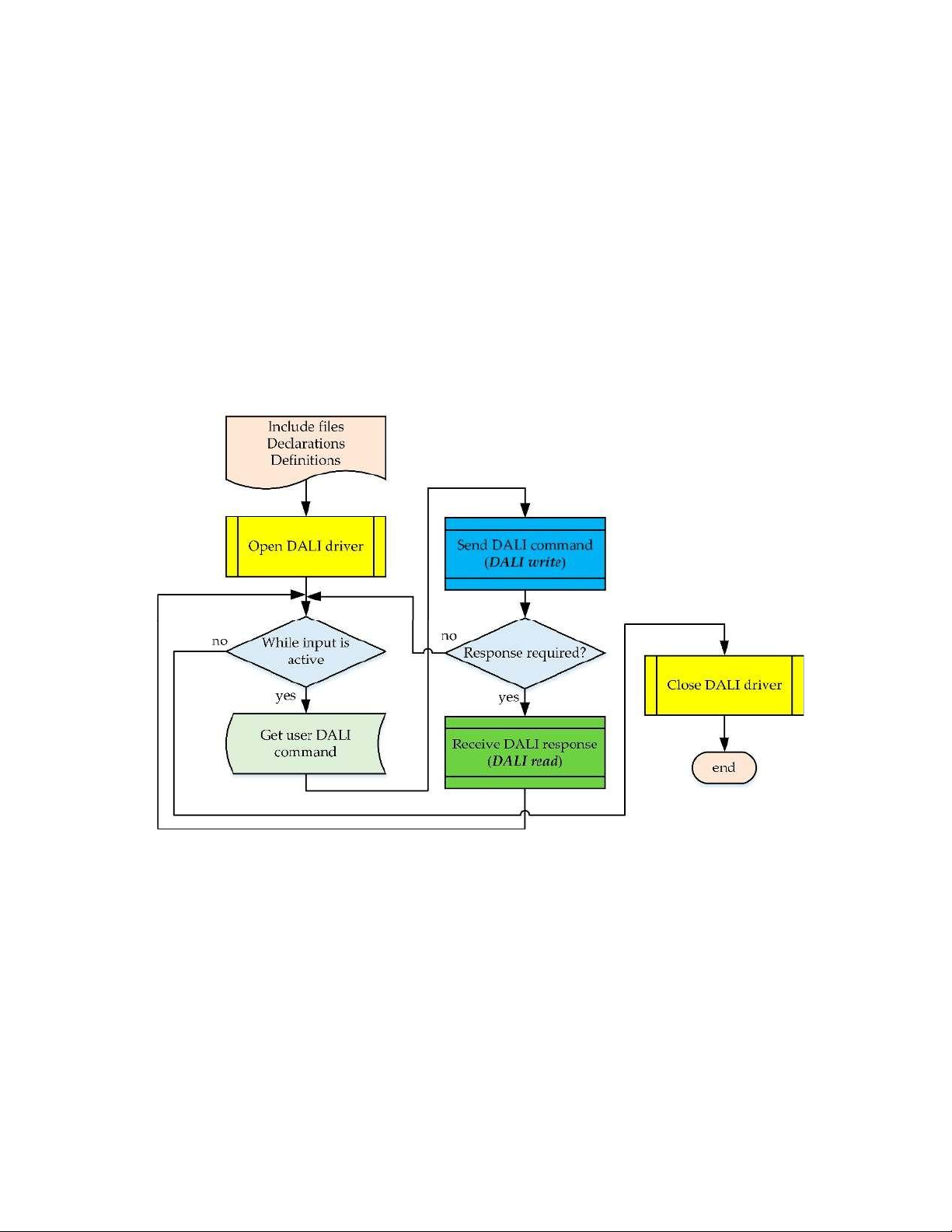
shown in Figure 7. An example application code in C, running in user space, is shown in Appendix B.
Figure 7. DALI template application program flow.
Once the DALI driver opens successfully, the main program loop (while loop) is started. The
main loop runs cyclically and is used to get user input, such as DALI commands, and perform the
actual transmission as forward frame commands to the DALI ballast, and receive back any response (backward frame data).
The application could be operated using the Python interface presented previously, or by
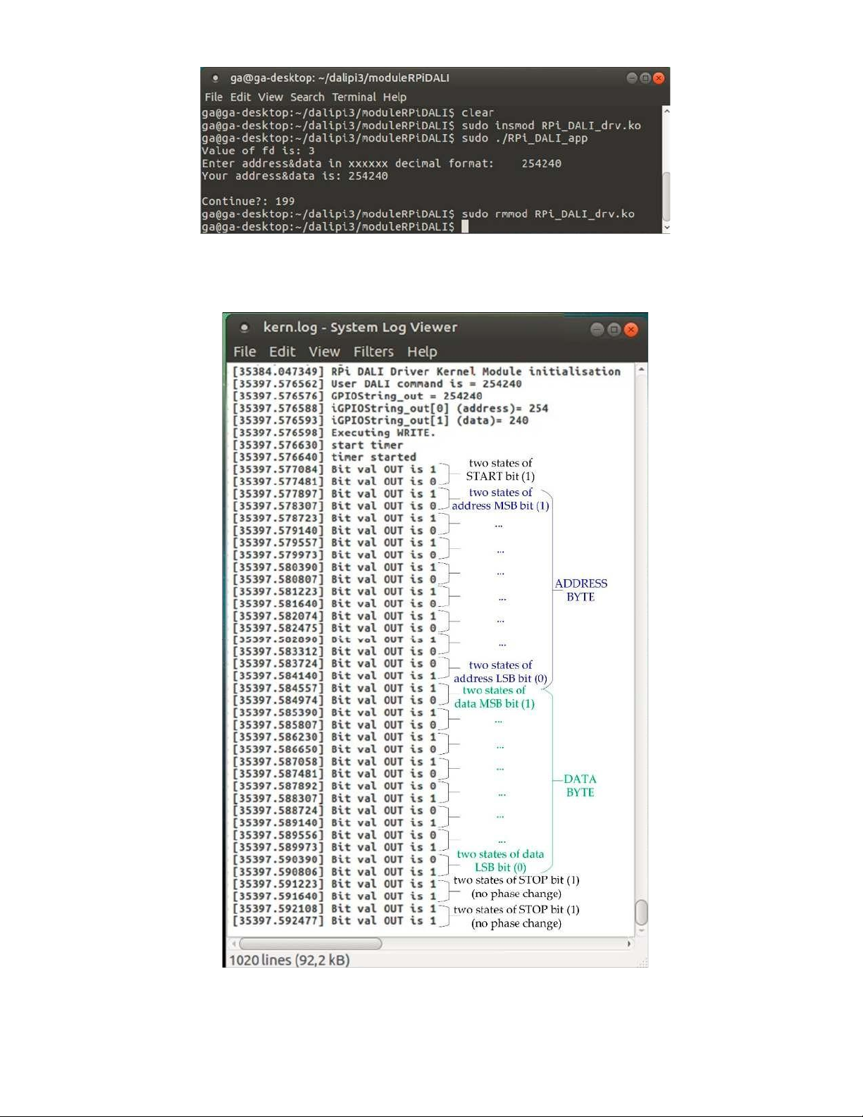
using a Mate Terminal for execution, as shown in Figure 8. As an example, a dimming operation is
shown, through the execution of a direct level command for setting the LED s arc power level at
value of 240 (hex: FEF0, dec:254240).
Figure 8. Console view of application execution.
Figure 9 shows a sample execution output of a direct level command for setting the LED s arc
power level at value of 240 (hex: FEF0, dec:254240, bin:1111111011110000).
Figure 9. DALI kernel module output execution of a direct arc level command (FEF0).
The application s format of forward_command is a decimal representation of the address and
data bytes defined as a string, e.g. 254240 (hex: FEF0, dec:254240, bin:1111111011110000). The DALI
driver module sends the forward_command as a DALI forward frame adding appropriate start and
stop bits (with no phase change). In particular, the driver module adds into that packet of bits one
start bit and two stop bits: 1111111101111000011. Then, every bit is represented and transmitted as
two states.The bits are sent MSB first. The packet is sent as a bi-phase Manchester encoded packet
(two states are sent for each bit). At a terminal we can monitor the execution of any DALI command
using the dmesg command or the system s Log File Viewer.
The outcome of the above experimentations proves the effectiveness of the developed kernel
module for DALI communication and control of a DALI LED driver. The source code of the software
applications and kernel module can be found in the supplementary material. 6.2. Discussion
We performed the presented work in order, among other goals, to prove the concept of using a
low-cost, low-power, open-source embedded control system for the communication and control of
standard DALI ballast drivers, based on commonly available microcontrollers such as Raspberry Pi3.
The RPi3-based DALI LED driver control system developed was shown to behave according to the
design criteria and issues. The DALI control signals provided by the microcontroller were shown to
operate appropriately the output of the LED under control. The whole system response of the RPi3,
the DALI LED driver and the LED chip together, is in the order of microseconds, sufficient for most application purposes.
The hardware implementation approach was designed to be easily set up for fast construction
and testing purposes. The design is modular, so the RPi3 DALI control module can be used to drive
the majority of DALI LED drivers (DALI ballasts) allowing the end-users to select lighting devices
based on their individual needs. The RPi3 supports various programming environments and
therefore, DALI control applications making use of the developed DALI kernel module could be
written in various programming languages.
By choosing open-source solutions both in respect to hardware (RPi3) and programming
environments (C, Python), the capabilities to modify the proposed RPi3-based DALI LED driver
control system are greatly broadened by the active user communities that exist around Raspberry Pi
(http://www.raspberrypi.org/) and Python (https://www.python.org/community/). This direction
adds to the availability of the application source code as an open-source project at GitHub public
repository https://github.com/gadam2018/RPi3-DALI.
The DALI LED driver control system based on the RPi3 microcontroller prototyping platform
was found to be suitable for controlling LEDs in our applications. The system can be used for a wide
range of DALI lighting control applications in educational and research environments with limited
budgets or technical skills, and in particular for researchers, students and universities with limited resources. 7. Conclusions
This paper presents the implementation of a DALI LED driver control system, based on a
Raspberry Pi3 Model B microcontroller board. The system runs UBUNTU 18.04.2 LTS patched with
PREEMPT_RT for real-time processing. The main control software is developed as a Linux kernel
module that performs all the processing, communication and control operations of the RPi3 DALI
controller with the DALI ballast (DALI LED driver) and luminaire. It generates appropriately
Manchester encoded control signals for digital lighting operations (e.g. dimming) and other viewing
or modification purposes (e.g. maintenance tasks and energy status info). Software applications
written in C and Python were developed for performance testing purposes.
The overall control system has the ability to operate and control DALI LED drivers and perform
lighting operations (e.g. dimming). The validity of the proposed system was evaluated through
actual experiments on LED driver dimming. The experimental results of the working prototype
provide evidence that the system performs correctly. In particular, the DALI control signals by the
RPi3-based DALI LED driver control system were shown to operate appropriately the output of the
LED under control. The kernel modules-based control software transforms dimming commands into
appropriate DALI control signals, which apply adequate dimming levels that control the
illumination of the LED. For instance, in the case of these laboratory experiments, the LED s intensity
is varied accordingly based on the execution of direct level commands (e.g. arc power level at value
240) setting the brightness value at different levels of the logarithmic dimming curve. The whole
system response is in the order of microseconds, sufficient for most application purposes.
Some of the key features of the implemented control system can be summarized into the following:
• Open-source, low-cost, low-power, embedded control architecture, based on Raspberry Pi3,
easily reprogrammed and reconfigured for integration with other lighting automation building systems.
• Linux kernel with real-time capabilities with the real-time patch PREEMPT_RT in UBUNTU,
capable to support future advanced timing control requirements.
• Dynamic loadable software control modules, based on Linux kernel modules, give flexibility to
the DALI driver controller and save RAM storage space, usually limited in embedded devices.
• Capable to wirelessly connect for control and monitoring purposes using one of the standard
connection protocols (e.g. Wi-Fi, Bluetooth)
The system could be used for a variety of purposes from personal lighting control needs and
experimental research in control of electronic ballasts and other control gears, devices and sensors,
to advanced requirements in professional buildings, including energy management, lighting maintenance and usage.
Supplementary Materials: The following are available online at www.mdpi.com/xxx/s1.
Funding: This research received no external funding.
Acknowledgments: The author wants to acknowledge all the laboratory personnel and technicians for their technical support.
Conflicts of Interest: The author declares no conflict of interest. Appendix A
/* Python application interface and shared library DALI_C_functions partial code */
#RPi3 DALI Controller Python Application
Interface import tkinter as tk from tkinter import *
from tkinter import ttk import ctypes _C_DALI_func =
ctypes.CDLL(’/home/ga/dalipi3/moduleRPiDALI/libdali.so’) class
Application(tk.Frame): def __init__(self, master=None):
super().__init__(master) self.master = master
self.master.title("RPi3 DALI Controller Application Interface") self.pack() def DALI_write():
address=self.address_entry.get() data=self.data_entry.get()
adddat= int(address + data) #print (adddat)
ret = _C_DALI_func.C_DALI_write(adddat)
print (ret) def DALI_read(): ret =
_C_DALI_func.C_DALI_read() print (ret) v.set(ret) #self.datainfo_entry=ret ..
self.send_button = Button(self, text = "Send command", command = DALI_write)
self.receive_response = Button(self, text = "Receive response", command = DALI_read) root = tk.Tk() app = Application(master=root) app.mainloop()
// Shared .so library used by Python RPi3_DALI_Controller_interface
//functions: C_DALI_write() & C_DALI_read() #include #include
//gcc -fPIC -shared -o libdali.so DALI_C_functions.c
int fd = open("/dev/RPi_DALI_drv", O_RDWR );
int C_DALI_write(int DALI_command) { char buffer[10];
printf("DALI_command is %d\n",DALI_command);
fd = open("/dev/RPi_DALI_drv", O_RDWR ); //printf( "Value of fd is: %d\n", fd ); if( fd < 0 ){
printf("Cannot open device \t"); printf(" fd = %d \n",fd); return -1;}
sprintf(buffer,"%d",DALI_command); //printf("DALI_command as a string is %s",buffer); write( fd, buffer, 1 ); return 0; } int C_DALI_read() { char gpio_buffer[10]; read( fd, gpio_buffer, 1);
if( 0 != close(fd) ) {printf("Could not close device\n"); return -1; return atoi(gpio_buffer); } Appendix B
/* Makefile and C Application partial code */
The driver module (RPi_DALI_drv.c) was compiled (make) with the following Makefile:
KERN_SRC:= /lib/modules/$(shell uname -r)/build PWD := $(shell pwd) obj-m := RPi_DALI_drv.o all:
make -C $(KERN_SRC) M=$(PWD) modules clean:
make -C $(KERN_SRC) M=$(PWD) clean //C example application code #include #include
#define DALI_drv "/dev/RPi_DALI_drv" //kernel-module C name (in devices dir) int main(void){
int fd = open(DALI_drv, O_RDWR );
char forward_command [10], backward_command [10]; while (1) {
// decimal format of command input: Address and Data bytes as a
string scanf( "%s", forward_command); // command input, e.g. 255000, (FF 00) an indirect OFF
command write( fd, forward_command, 1 ); // calls DALI_write file operation to send the command to the DALI LED driver
read( fd, backward_command, 1); }// calls DALI_read file operation to receive any answer from the
DALI LED driver close(fd); return 0;} References 1.
Liang, Z.; Shen, H.-G. Survey on Building Energy Consumption Using Statistics Principle. In Proceedings
of the International Conference on Digital Manufacturing & Automation, Changsha, China, 18 20 December
2010; pp. 585 589, doi:10.1109/ICDMA.2010.302. 2.
Yun, G.Y.; Kong, H.J.; Kim, H.; Kim, J.T. A field survey of visual comfort and lighting energy consumption
in open plan offices. Energy Build. 2012, 46, 146 151. 3.
Gonzalo, F.; Hernandez, J.A.; Moreno, B. Electrical energy consumption in buildings by means of
experimental measurements: Analysis of an educational facility. In Proceedings of the International
Conference on Electrical and Computing Technologies and Applications (ICECTA 2017), Ras Al Khaimah,
United Arab Emirates, 21 23 November 2017; doi:10.1109/ICECTA.2017.8251976. 4.
Bakker, C.; Aries, M.; Kort, H.; Rosemann, A. Occupancy-based lighting control in open-plan office spaces:
A state-of-the-art review. Build. Environ. 2017, 112, 308 321. 5.
Li, D.H.; Cheung, K.; Wong, S.; Lam, T.N. An analysis of energy-efficient light fittings and lighting controls.
Appl. Energy 2010, 87, 558 567. 6.
Soori, P.K.; Vishwas, M. Lighting control strategy for energy efficient office lighting system design. Energy
Build. 2013, 66, 329 337. 7.
Xu, L.; Pan, Y.; Yao, Y.; Cai, D.; Huang, Z.; Linder, N. Lighting energy efficiency in offices under different
control strategies. Energy Build. 2017, 138, 127 139. 8.
Van Driel, W.; Schuld, M.; Jacobs, B.; Commissaris, F.; Van Der Eyden, J.; Hamon, B. Lumen maintenance
predictions for LED packages. Microelectron. Reliab. 2016, 62, 39 44. 9.
Nardelli, A.; Deuschle, E.; De Azevedo, L.D.; Pessoa, J.L.N.; Ghisi, E. Assessment of Light Emitting Diodes
technology for general lighting: A critical review. Renewable Sustainable Energy Rev. 2017, 75, 368 379.
10. Lee, C.K.; Li, S.; Hui, S.Y. A Design Methodology for Smart LED Lighting Systems Powered By Weakly
Regulated Renewable Power Grids. IEEE Trans. Smart Grid 2011, 2, 548 554.
11. Cheng, Y.-S.; Chen, J.-H.; Liu, Y.-H.; Wang, S.-C. Development of wireless RGB LED dimming control
technology using smart phone. In Proceedings of the 2014 International Conference on Intelligent Green
Building and Smart Grid (IGBSG 2014), Taipei, Taiwan, 23 25 April 2014; doi:10.1109/IGBSG.2014.6835220.
12. Su, Z. Design of White Light LED Lighting Control System. In Proceedings of the International Conference
on Intelligent Transportation, Big Data & Smart City (ICITBS 2018), Xiamen, China, 25 26 January 2018;
doi:10.1109/ICITBS.2018.00147.
13. Svilainis, L. LED PWM dimming linearity investigation. Displays 2008, 29, 243 249.
14. Patel, M.; Mukherjee, S. Lighting Control Protocols and Standards. In Handbook of Advanced Lighting
Technology; Karlicek, R., Sun, C.-C., Eds.; Springer International Publishing AG: Cham, Switzerland, 2017; pp. 559 582.
15. International Electrotechnical Commission. IEC 60929:2011. AC and/or DC-supplied electronic control gear for tubular fluorescent lamps Performance requirements. Available
online: https://webstore.iec.ch/publication/3926 (accessed on 10 February 2018).
16. International Electrotechnical Commission. IEC 62386-201:2015. Digital Addressable Lighting Interface
Part 201: Particular requirements for control gear Fluorescent lamps. Available online:
https://webstore.iec.ch/publication/22534 (accessed on 27 April 2018).
17. Ibrahim, D. Using LEDs, LCDs and GLCDs in Microcontroller Projects, 1st ed.; John Wiley & Sons, LLC:
Chichester, West Sussex, UK, 2012; ISBN 978-11-1994-070-8.
18. Dean, A.G. Embedded Systems Fundamentals with ARM Cortex-M based Microcontrollers: A Practical Approach;
ARM Education Media UK: Cambridge, UK, 2017; ISBN 978-19-1153-103-6.
19. Bai, Y. Practical Microcontroller Engineering with ARM‹ Technology, 1st ed.; John Wiley & Sons, Inc.: Hoboken,
NJ, USA, 2015; ISBN 978-11-1905-237-1.
20. Jimenez, R. Microcontroller Engineer s Notebook. 12 Experiments with PIC12F683, 1st ed.; World Class Micro
Electronics: Calexico, CA, USA, 2016; ISBN 978-06-9276-419-0.
21. Ferreira, J.C.; Afonso, J.A.; Monteiro, V.; Afonso, J.L. An Energy Management Platform for Public Buildings.
Electronics 2018, 7, 1 13, doi: 10.3390/electronics7110294.
22. Abdalaal, R.M.; Ho, C.N.M.; Leung, C.K.; Ohin, N.I.; Rehman, S.H. A Remotely Control Dimming System
for LED Lamps with Power Factor Correction. In Proceedings of the IEEE Energy Conversion Congress
and Exposition (ECCE 2018), Portland, OR, USA, 23 27 September 2018; pp. 4721 4727; doi: 10.1109/ECCE.2018.8557944.
23. Basil, E.; Sawant, S.D. IoT based traffic light control system using Raspberry Pi. In Proceedings of the
International Conference on Energy, Communication, Data Analytics and Soft Computing (ICECDS 2017),
Chennai, India, 1 2 August 2017; pp. 1078 1081; doi: 10.1109/ICECDS.2017.8389604.
24. Urgiles, M.V.; Arpi, P.E.; Chacon-Troya, D.P. Lighting control actuator design and development for a
ZigBee network with a Web server mounted on Raspberry Pi. In Proceedings of the IEEE International
Conference on Automation Science and Engineering (CASE 2015), Gothenburg, Sweden, 24 28 August 2015;
pp. 714 719; doi: 10.1109/CoASE.2015.7294165.
25. Ardito, L; Torchiano, M. Creating and evaluating a software power model for linux single board computers.
In Proceedings of the 6th International Workshop on Green and Sustainable Software, Gothenburg,
Sweden, 27 May 2018; pp. 1 8; doi:10.1145/3194078.3194079.
26. Membrey, P.; Veitch, D.; Chang, R.K.C. Time to Measure the Pi. In Proceedings of the ACM Internet
Measurement Conference (IMC 2016), Santa Monica, CA, USA, 14 16 November 2016; pp. 327 334; doi:10.1145/2987443.2987476.
27. The Linux Foundation. Real Time Linux. Available online: https://www.linuxfoundation.org/ (accessed on 24 March 2019).
28. Han, D.-M.; Lim, J.-H. Design and implementation of smart home energy management systems based on
zigbee. IEEE Trans. Consum. Electron. 2010, 56, 1417 1425.
29. Smith, C.B.; Parmenter, K.E. Energy Management Principles - Applications, Benefits, Savings, 2nd ed.; Elsevier:
Amsterdam, Netherlands, 2015; ISBN 978-0-12-802506-2.
30. Gao, Y.; Cheng, Y.; Zhang, H.; Zou, N. Dynamic illuminance measurement and control used for smart
lighting with LED. Measurement. 2019, 139, 380 386.
31. Wang, S.; Liu, Y.; Chen, Y-L.; Chen J-Y. Development of DALI-based electronic ballast with energy saving
control for ultraviolet lamps. In Proceedings of the 2010 8th IEEE International Conference on Industrial
Informatics, Osaka, Japan, 13 16 July 2010; pp. 214 219; doi:10.1109/INDIN.2010.5549427.
32. Pinto, M.F.; Soares, G.M.; Mendon a, T.R.F.; Almeida, P.S.; Braga, H.A.C. Smart modules for lighting system
applications and power quality measurements. In Proceedings of the 11th IEEE/IAS International
Conference on Industry Applications, Juiz de Fora, Brazil, 7 10 December 2014; pp. 1 8;
doi:10.1109/INDUSCON.2014.7059448.
33. Teikari, P.; Najjar, R.P.; Malkki, H.; Knoblauch, K.; Dumortier, D.; Gronfier, C.; Cooper, H.M. An
inexpensive Arduino-based LED stimulator system for vision research. J. Neurosci. Methods 2012, 211, 227 236.
34. Nodado, J.T.G.; Morales, H.C.P.; Abugan, M.A.P.; Olisea, J.L.; Aralar,A.C.; Loresco, P.J.M. Intelligent Traffic
Light System Using Computer Vision with Android Monitoring and Control. In Proceedings of the
Tài liệu liên quan:
-

Arduino UNO R3 Reference Manual: Features & Applications Guide | Môn Hệ thống nhúng trong công nghiệp - Đại học Sư phạm Kỹ thuật Thành phố Hồ Chí Minh
122 61 -

Building XOR Gate Using AND, OR, and NOT Gates | Môn Hệ thống nhúng trong công nghiệp - Đại học Sư phạm Kỹ thuật Thành phố Hồ Chí Minh
159 80 -

Báo cáo tuần 1: Hệ thống nhúng và Cài đặt MPLAB, XC18 | Môn Hệ thống nhúng trong công nghiệp - Đại học Sư phạm Kỹ thuật Thành phố Hồ Chí Minh
103 52 -

Đo mực nước hiển thị lên web online sử dụng cảm biến siêu âm có buzzer cảnh báo đầy | Môn Hệ thống nhúng trong công nghiệp - Đại học Sư phạm Kỹ thuật Thành phố Hồ Chí Minh
108 54