Động Cơ: Tính Toán Tốc Độ, Lượng Khí, và Tỷ Lệ Nhiên Liệu | Cơ sở thủy khí ứng dụng | Trường Đại học Khoa học Tự nhiên, Đại học Quốc gia Hà Nội
Example 2: A two-spool forward unmixed turbofan engine is powering an airliner flying at Mach number M = 0,9 at an altitude of H = 10.500 m (ambient pressure, temperature, sonic speed, and air density ratio are Pa = 24.475 Pa, T = 220 K, V = 297,3 m/s, and 0,3165, respectively). The low-pressure spool is composed of a turbine driving the fan and the low-pressure compressor. Tài liệu được sưu tầm và soạn thảo dưới dạng file PDF để gửi tới các bạn cùng tham khảo, ôn tập đầy đủ kiến thức, chuẩn bị cho các buổi học thật tốt. Mời bạn đọc đón xem!
Môn: Cơ sở thủy khí ứng dụng 10 tài liệu
Trường: Trường Đại học Khoa học tự nhiên, Đại học Quốc gia Hà Nội 1.1 K tài liệu
Tác giả:
Preview text:
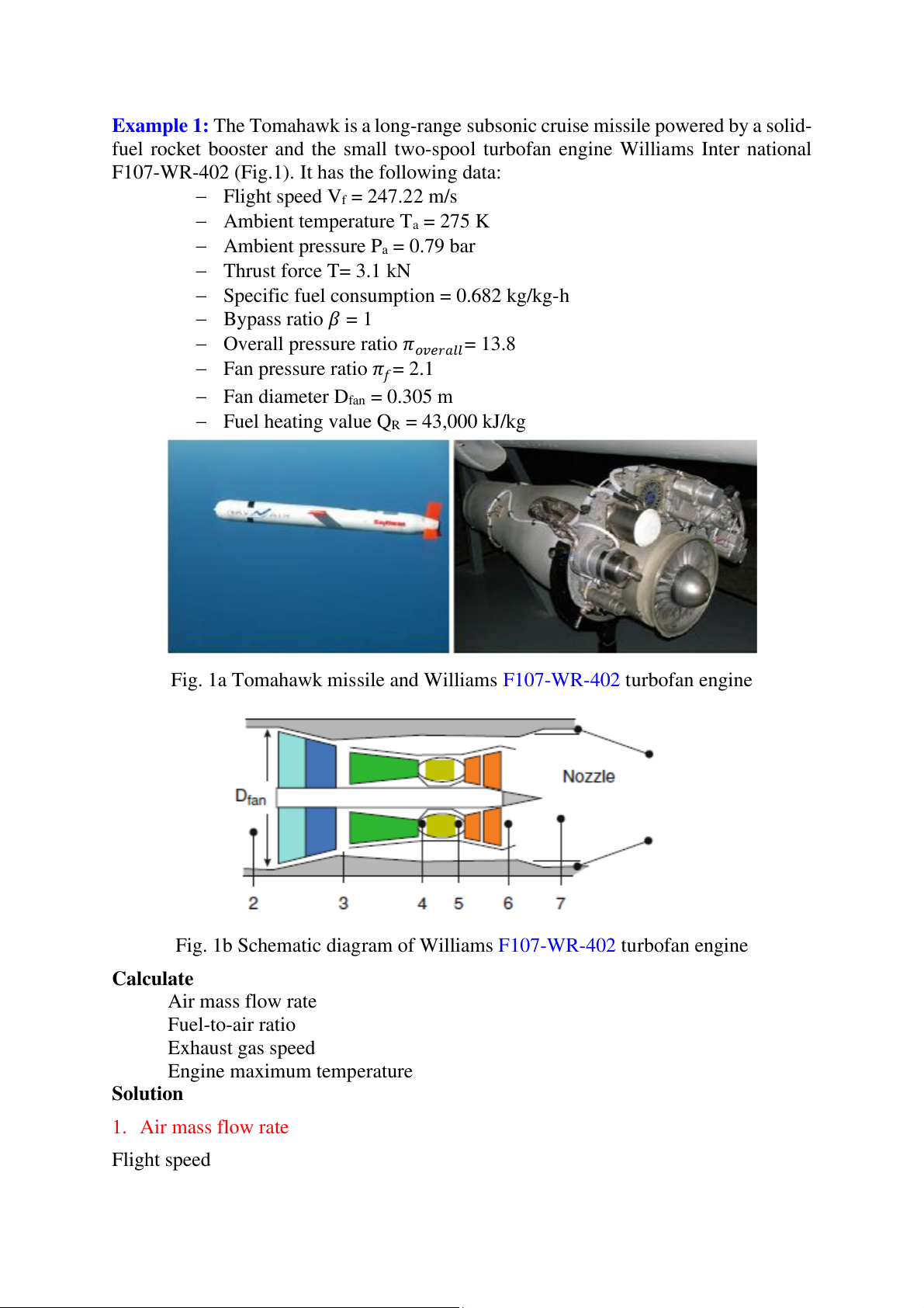
Example 1: The Tomahawk is a long-range subsonic cruise missile powered by a solid-
fuel rocket booster and the small two-spool turbofan engine Williams Inter national
F107-WR-402 (Fig.1). It has the following data:
− Flight speed Vf = 247.22 m/s
− Ambient temperature Ta = 275 K
− Ambient pressure Pa = 0.79 bar − Thrust force T= 3.1 kN
− Specific fuel consumption = 0.682 kg/kg-h − Bypass ratio 𝛽 = 1
− Overall pressure ratio 𝜋𝑜𝑣𝑒𝑟𝑎𝑙𝑙= 13.8
− Fan pressure ratio 𝜋𝑓= 2.1
− Fan diameter Dfan = 0.305 m
− Fuel heating value QR = 43,000 kJ/kg
Fig. 1a Tomahawk missile and Williams F107-WR-402 turbofan engine
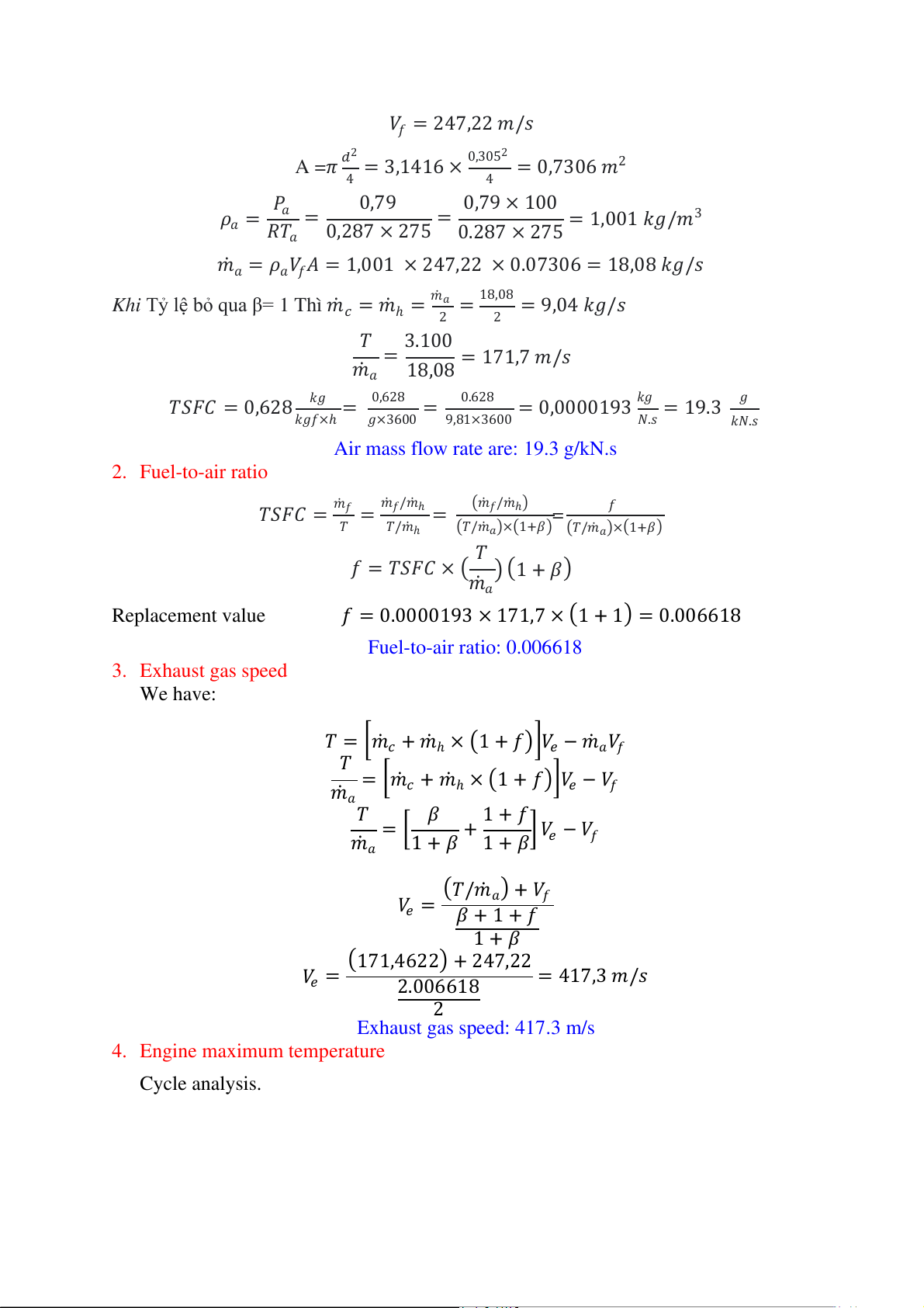
Fig. 1b Schematic diagram of Williams F107-WR-402 turbofan engine Calculate Air mass flow rate Fuel-to-air ratio Exhaust gas speed Engine maximum temperature Solution 1. Air mass flow rate Flight speed 𝑉𝑓 = 247,22 𝑚/𝑠
A =𝜋 𝑑2 = 3,1416 × 0,3052 = 0,7306 𝑚2 4 4 𝑃 0,79 0,79 × 100 𝜌 𝑎 3 𝑎 = 𝑅𝑇 = = = 1,001 𝑘𝑔/𝑚 𝑎 0,287 × 275 0.287 × 275
𝑚𝑎 = 𝜌𝑎𝑉𝑓𝐴 = 1,001 × 247,22 × 0.07306 = 18,08 𝑘𝑔/𝑠
Khi Tỷ lệ bỏ qua β= 1 Thì 𝑚𝑐 = 𝑚ℎ = 𝑚𝑎 = 18,08 = 9,04 𝑘𝑔/𝑠 2 2 𝑇 3.100 𝑚 = = 171,7 𝑚/𝑠 𝑎 18,08
𝑇𝑆𝐹𝐶 = 0,628 𝑘𝑔 = 0,628 = 0.628 = 0,0000193 𝑘𝑔 = 19.3 𝑔 𝑘𝑔𝑓×ℎ 𝑔×3600 9,81×3600 𝑁.𝑠 𝑘𝑁.𝑠
Air mass flow rate are: 19.3 g/kN.s 2. Fuel-to-air ratio
𝑇𝑆𝐹𝐶 = 𝑚𝑓 = 𝑚𝑓/𝑚ℎ = (𝑚𝑓/𝑚ℎ) = 𝑓 𝑇 𝑇/𝑚ℎ (𝑇/𝑚𝑎)× 1+𝛽 (
) (𝑇/𝑚𝑎)×(1+𝛽) 𝑇
𝑓 = 𝑇𝑆𝐹𝐶 × (𝑚 )(1 + 𝛽) 𝑎
Replacement value 𝑓 = 0.0000193 × 171,7 × (1 + 1) = 0.006618 Fuel-to-air ratio: 0.006618 3. Exhaust gas speed We have:
𝑇 = [𝑚𝑐 + 𝑚ℎ × (1 + 𝑓)]𝑉𝑒 − 𝑚𝑎𝑉𝑓 𝑇 ]
𝑚 = [𝑚𝑐 + 𝑚ℎ × (1 + 𝑓) 𝑉𝑒 − 𝑉𝑓 𝑎𝑇 𝛽 1 + 𝑓 𝑚 = [ 𝑎
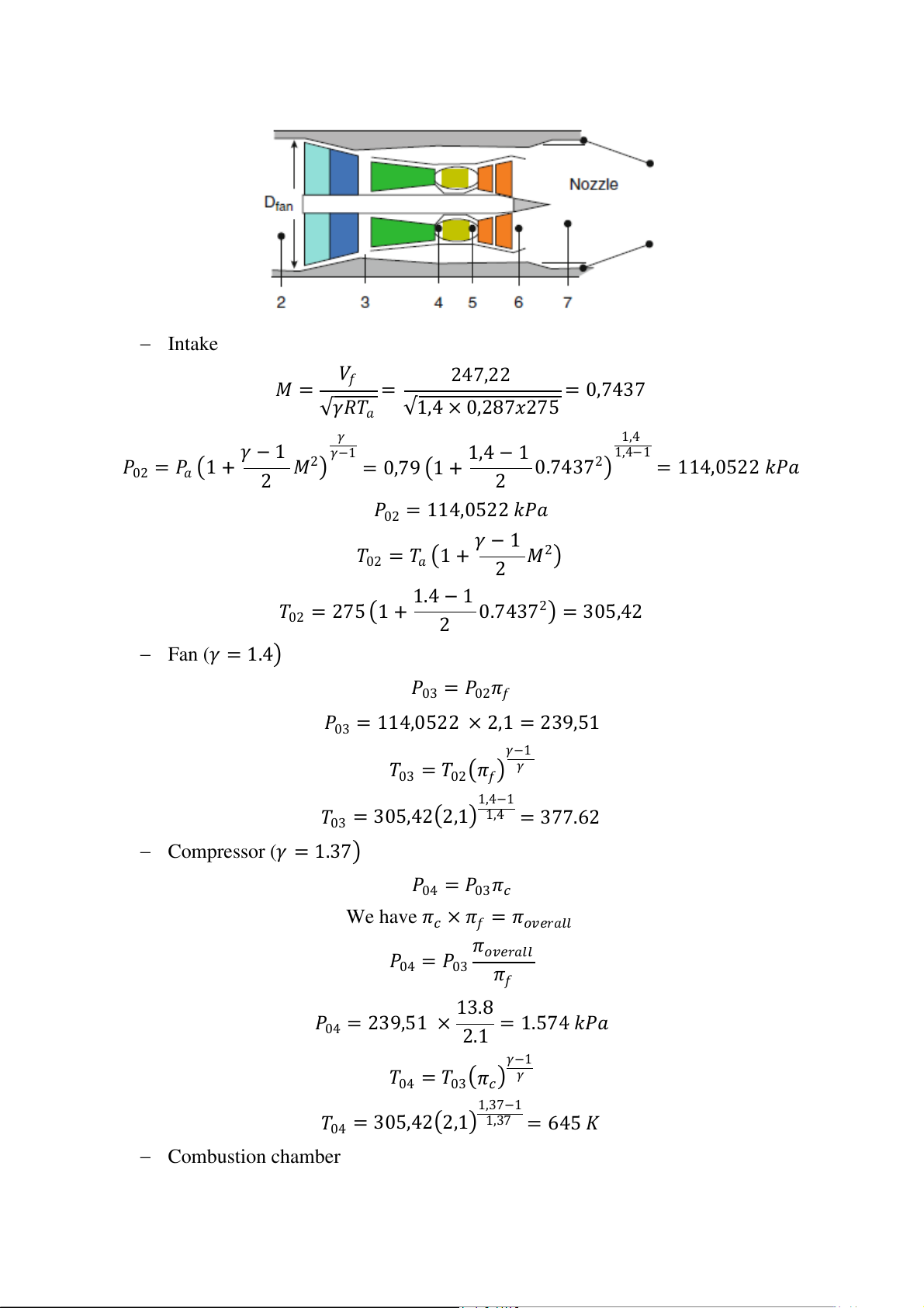
1 + 𝛽 + 1 + 𝛽] 𝑉𝑒 − 𝑉𝑓 (𝑇/𝑚 𝑉 𝑎) + 𝑉𝑓 𝑒 = 𝛽 + 1 + 𝑓 1 + 𝛽 (171,4622) + 247,22 𝑉𝑒 = 2.006618 = 417,3 𝑚/𝑠 2 Exhaust gas speed: 417.3 m/s 4. Engine maximum temperature Cycle analysis. − Intake 𝑉 𝑀 = 𝑓 247,22 = = 0,7437
√𝛾𝑅𝑇𝑎 √1,4 × 0,287𝑥275 𝛾 1,4 𝛾 − 1 1,4−1 𝑃 𝛾−1 1,4 − 1 02 = 𝑃𝑎 (1 + 2 𝑀2) = 0,79 (1 + 2 0.74372) = 114,0522 𝑘𝑃𝑎
𝑃02 = 114,0522 𝑘𝑃𝑎 𝛾 − 1
𝑇02 = 𝑇𝑎 (1 + 2 𝑀2) 1.4 − 1 𝑇02 = 275 (1 + 2 0.74372) = 305,42 − Fan (𝛾 = 1.4) 𝑃03 = 𝑃02𝜋𝑓
𝑃03 = 114,0522 × 2,1 = 239,51 𝛾−1 𝑇 𝛾 03 = 𝑇02(𝜋𝑓) 1,4−1
𝑇03 = 305,42(2,1) 1,4 = 377.62 − Compressor (𝛾 = 1.37) 𝑃04 = 𝑃03𝜋𝑐
We have 𝜋𝑐 × 𝜋𝑓 = 𝜋𝑜𝑣𝑒𝑟𝑎𝑙𝑙 𝜋 𝑃 𝑜𝑣𝑒𝑟𝑎𝑙𝑙 04 = 𝑃03 𝜋𝑓 13.8
𝑃04 = 239,51 × 2.1 = 1.574 𝑘𝑃𝑎 𝛾−1
𝑇04 = 𝑇03(𝜋𝑐) 𝛾 1,37−1
𝑇04 = 305,42(2,1) 1,37 = 645 𝐾 − Combustion chamber
𝑚𝑓𝑄𝑅 + 𝑚ℎ𝐶𝑝𝑐𝑇04 = (𝑚ℎ + 𝑚𝑓)𝐶𝑝ℎ𝑇05 𝑓𝑄 𝑇 𝑅 + 𝐶𝑝𝑐𝑇04 05 = ( 1 + 𝑓)𝐶𝑝ℎ
0.006618 × 43000 + 1.005 × 645 𝑇05 = (1 + 0.006618)1.148 = 807.2 𝐾 Maximum temperature is then T 0 0max = 807.2 K.
Example 2: A two-spool forward unmixed turbofan engine is powering an airliner
flying at Mach number M = 0,9 at an altitude of H = 10.500 m (ambient pressure,
temperature, sonic speed, and air density ratio are Pa = 24.475 Pa, T = 220 K, V = 297,3
m/s, and 0,3165, respectively). The low-pressure spool is composed of a turbine driving
the fan and the low-pressure compressor. The high-pressure spool is composed of a
high-pressure compressor and a high-pressure turbine. Air is bled from the outlet of
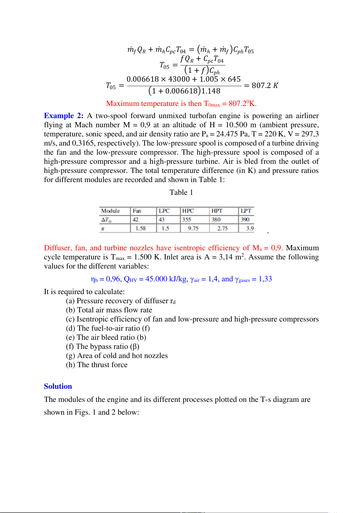
high-pressure compressor. The total temperature difference (in K) and pressure ratios
for different modules are recorded and shown in Table 1: Table 1 `
Diffuser, fan, and turbine nozzles have isentropic efficiency of Ma = 0,9. Maximum cycle temperature is T 2
max = 1.500 K. Inlet area is A = 3,14 m . Assume the following
values for the different variables:
ηb = 0,96, QHV = 45.000 kJ/kg, γair = 1,4, and γgases = 1,33 It is required to calculate:
(a) Pressure recovery of diffuser rd (b) Total air mass flow rate
(c) Isentropic efficiency of fan and low-pressure and high-pressure compressors (d) The fuel-to-air ratio (f) (e) The air bleed ratio (b) (f) The bypass ratio (β)
(g) Area of cold and hot nozzles (h) The thrust force Solution
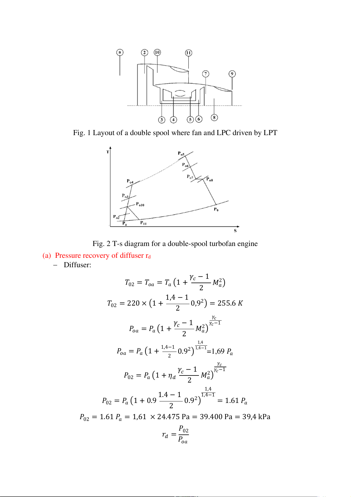
The modules of the engine and its different processes plotted on the T-s diagram are shown in Figs. 1 and 2 below:
Fig. 1 Layout of a double spool where fan and LPC driven by LPT
Fig. 2 T-s diagram for a double-spool turbofan engine
(a) Pressure recovery of diffuser rd − Diffuser: 𝛾 𝑇 𝑐 − 1 2
02 = 𝑇𝑜𝑎 = 𝑇𝑎 (1 + 2 𝑀𝑎) 1,4 − 1 𝑇02 = 220 × (1 + 2 0,92) = 255.6 𝐾 𝛾 𝛾 𝑐 𝛾 𝑃 𝑐 − 1 2 𝑐−1 𝑜𝑎 = 𝑃𝑎 (1 + 2 𝑀𝑎) 1,4 𝑃 1,4−1
𝑜𝑎 = 𝑃𝑎 (1 + 1,4−1 0.92) =1,69 𝑃 2 𝑎 𝛾 𝛾 𝑐 𝛾 𝑃 𝑐 − 1 2 𝑐−1 02 = 𝑃𝑎 (1 + 𝜂𝑑 2 𝑀𝑎) 1,4 1.4 − 1 1,4−1 𝑃02 = 𝑃𝑎 (1 + 0.9 2 0.92) = 1.61 𝑃𝑎
𝑃02 = 1.61 𝑃𝑎 = 1,61 × 24.475 Pa = 39.400 Pa = 39,4 kPa 𝑃 𝑟 02 𝑑 = 𝑃𝑜𝑎 1.61 𝑃𝑎
𝑟𝑑 = 1.69 𝑃𝑎 = 0,953
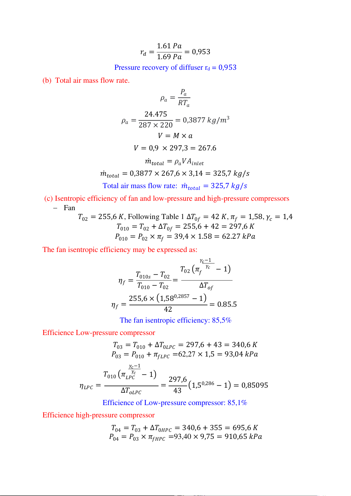
Pressure recovery of diffuser rd = 0,953 (b) Total air mass flow rate. 𝑃 𝜌 𝑎 𝑎 = 𝑅𝑇𝑎 24.475
𝜌𝑎 = 287 × 220 = 0,3877 𝑘𝑔/𝑚3 𝑉 = 𝑀 × 𝑎 𝑉 = 0,9 × 297,3 = 267.6
𝑚𝑡𝑜𝑡𝑎𝑙 = 𝜌𝑎𝑉𝐴𝑖𝑛𝑙𝑒𝑡
𝑚𝑡𝑜𝑡𝑎𝑙 = 0,3877 × 267,6 × 3,14 = 325,7 𝑘𝑔/𝑠
Total air mass flow rate: 𝑚𝑡𝑜𝑡𝑎𝑙 = 325,7 𝑘𝑔/𝑠
(c) Isentropic efficiency of fan and low-pressure and high-pressure compressors
− Fan 𝑇02 = 255,6 𝐾, Following Table 1 ∆𝑇0𝑓 = 42 𝐾, 𝜋𝑓 = 1,58, 𝛾𝑐 = 1,4
𝑇010 = 𝑇02 + ∆𝑇0𝑓 = 255,6 + 42 = 297,6 𝐾
𝑃010 = 𝑃02 × 𝜋𝑓 = 39,4 × 1.58 = 62.27 𝑘𝑃𝑎
The fan isentropic efficiency may be expressed as: 𝛾𝑐−1 𝛾𝑐 𝑇 𝑇02 (𝜋𝑓 − 1) 𝜂 010𝑠 − 𝑇02 𝑓 = 𝑇 = 010 − 𝑇02 ∆𝑇𝑜𝑓 255,6 × (1,580,2857 − 1) 𝜂𝑓 = 42 = 0.85.5
The fan isentropic efficiency: 85,5%
Efficience Low-pressure compressor
𝑇03 = 𝑇010 + ∆𝑇0𝐿𝑃𝐶 = 297,6 + 43 = 340,6 𝐾
𝑃03 = 𝑃010 + 𝜋𝑓𝐿𝑃𝐶 =62,27 × 1,5 = 93,04 𝑘𝑃𝑎 𝛾𝑐−1 𝑇 𝛾𝑐 010 (𝜋𝐿𝑃𝐶 − 1) 297,6 𝜂 0,286 𝐿𝑃𝐶 = ∆𝑇 = (1,5 − 1) = 0,85095 𝑜𝐿𝑃𝐶 43
Efficience of Low-pressure compressor: 85,1%
Efficience high-pressure compressor
𝑇04 = 𝑇03 + ∆𝑇0𝐻𝑃𝐶 = 340,6 + 355 = 695,6 𝐾
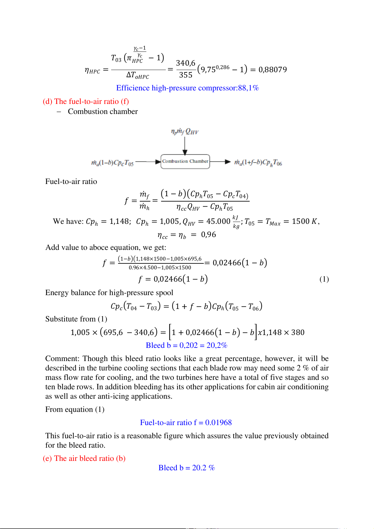
𝑃04 = 𝑃03 × 𝜋𝑓𝐻𝑃𝐶 =93,40 × 9,75 = 910,65 𝑘𝑃𝑎 𝛾𝑐−1 𝑇 𝛾𝑐 03 (𝜋𝐻𝑃𝐶 − 1) 340,6 𝜂𝐻𝑃𝐶 = ∆𝑇 = (9,750,286 − 1) = 0,88079 𝑜𝐻𝑃𝐶 355
Efficience high-pressure compressor:88,1% (d) The fuel-to-air ratio (f) − Combustion chamber Fuel-to-air ratio 𝑚 (1 − 𝑏)(𝐶𝑝 𝑓 = 𝑓
ℎ𝑇05 − 𝐶𝑝𝑐𝑇04) 𝑚 = ℎ
𝜂𝑐𝑐𝑄𝐻𝑉 − 𝐶𝑝ℎ𝑇05 We have: 𝐶𝑝 𝑘𝐽
ℎ = 1,148; 𝐶𝑝ℎ = 1,005, 𝑄𝐻𝑉 = 45.000 ; 𝑇 𝑘𝑔
05 = 𝑇𝑀𝑎𝑥 = 1500 𝐾,
𝜂𝑐𝑐 = 𝜂𝑏 = 0,96
Add value to aboce equation, we get:
𝑓 = (1−𝑏)(1,148×1500−1,00 ×695,6 5 = 0,02466(1 − 𝑏) 0.9 ×4. 6 500−1,005×1500 𝑓 = 0,02466(1 − 𝑏) (1)
Energy balance for high-pressure spool
𝐶𝑝𝑐(𝑇04 − 𝑇03) = (1 + 𝑓 − 𝑏)𝐶𝑝ℎ(𝑇05 − 𝑇06) Substitute from (1)
1,005 × (695,6 − 340,6) = [1 + 0,02466(1 − 𝑏) − 𝑏]𝑥1,148 × 380 Bleed b = 0,202 = 20,2%
Comment: Though this bleed ratio looks like a great percentage, however, it will be
described in the turbine cooling sections that each blade row may need some 2 % of air
mass flow rate for cooling, and the two turbines here have a total of five stages and so
ten blade rows. In addition bleeding has its other applications for cabin air conditioning
as well as other anti-icing applications. From equation (1) Fuel-to-air ratio f = 0.01968
This fuel-to-air ratio is a reasonable figure which assures the value previously obtained for the bleed ratio. (e) The air bleed ratio (b) Bleed b = 20.2 % (f) The bypass ratio (β)
Energy balance for low-pressure spool:
(1 + 𝛽)𝐶𝑝𝑐∆𝑇𝑜𝑓 + 𝐶𝑝𝑐∆𝑇𝑜𝐿𝑃𝑇 = (1 + 𝑓 − 𝑏)𝐶𝑝ℎ∆𝑇𝑜𝐿𝑃𝑇 Apply Value, we get:
(1 + 𝛽)1,005 × +1,005 × 43 = (1 + 0,01968 − 0,202) × 1,148 × 390 Or 𝛽 = 6,649
Thus, the bypass ratio is 𝛽 = 6,649
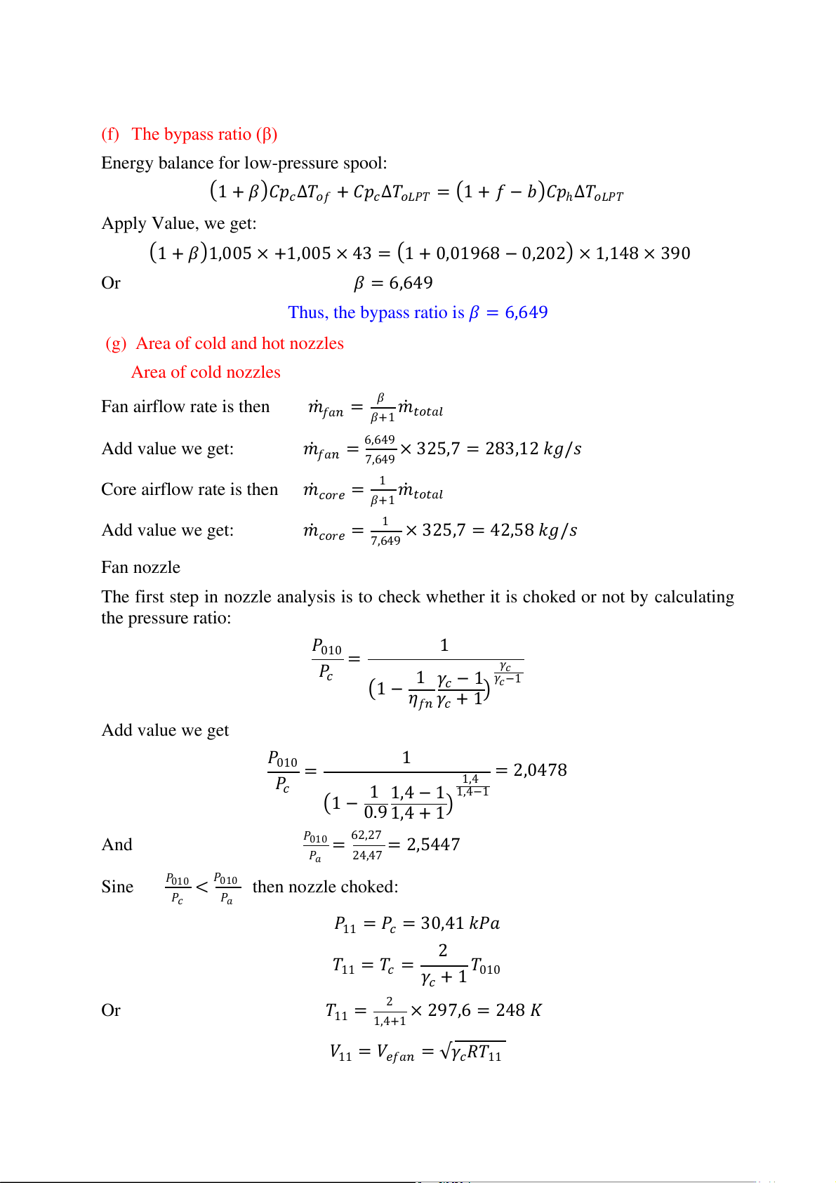
(g) Area of cold and hot nozzles Area of cold nozzles Fan airflow rate is then
𝑚𝑓𝑎𝑛 = 𝛽 𝑚 𝛽+1 𝑡𝑜𝑡𝑎𝑙 Add value we get:
𝑚𝑓𝑎𝑛 = 6,649 × 325,7 = 283,12 𝑘𝑔/𝑠 7,649
Core airflow rate is then 𝑚𝑐𝑜𝑟𝑒 = 1 𝑚 𝛽+1 𝑡𝑜𝑡𝑎𝑙 Add value we get:
𝑚𝑐𝑜𝑟𝑒 = 1 × 325,7 = 42,58 𝑘𝑔/𝑠 7,649 Fan nozzle
The first step in nozzle analysis is to check whether it is choked or not by calculating the pressure ratio: 𝑃010 1 𝑃 = 𝛾 𝑐 𝑐
(1 − 1 𝛾𝑐 − 1 𝛾𝑐−1 𝜂𝑓𝑛 𝛾𝑐 + 1) Add value we get 𝑃010 1 𝑃 = 1,4 = 2,0478 𝑐 (1 − 1 1,4 − 1 1,4−1 0.9 1,4 + 1) And 𝑃010 = 62,27 = 2,5447 𝑃𝑎 24,47
Sine 𝑃010 < 𝑃010 then nozzle choked: 𝑃𝑐 𝑃𝑎
𝑃11 = 𝑃𝑐 = 30,41 𝑘𝑃𝑎 2
𝑇11 = 𝑇𝑐 = 𝛾𝑐 + 1𝑇010 Or
𝑇11 = 2 × 297,6 = 248 𝐾 1,4+1
𝑉11 = 𝑉𝑒𝑓𝑎𝑛 = √𝛾𝑐𝑅𝑇11 Aad value
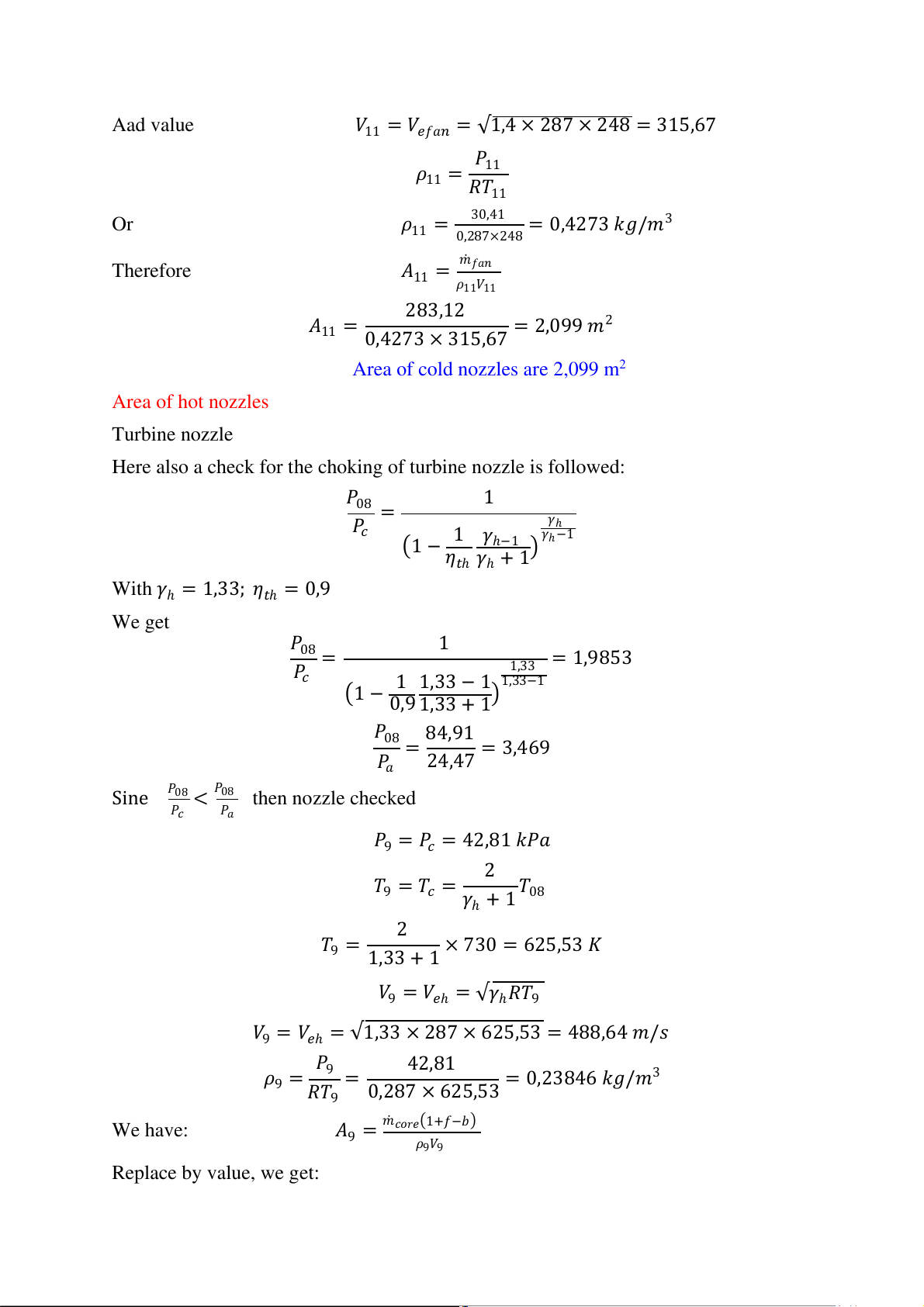
𝑉11 = 𝑉𝑒𝑓𝑎𝑛 = √1,4 × 287 × 248 = 315,67 𝑃 𝜌 11 11 = 𝑅𝑇11 Or 𝜌 3 11 = 30,41 = 0,4273 𝑘𝑔/𝑚 0,287×248 Therefore
𝐴11 = 𝑚𝑓𝑎𝑛 𝜌11𝑉11 283,12
𝐴11 = 0,4273 × 315,67 = 2,099 𝑚2
Area of cold nozzles are 2,099 m2 Area of hot nozzles Turbine nozzle
Here also a check for the choking of turbine nozzle is followed: 𝑃08 1 𝑃 = 𝛾 𝑐 ℎ
(1 − 1 𝛾ℎ−1 𝛾ℎ−1 𝜂𝑡ℎ 𝛾ℎ + 1)
With 𝛾ℎ = 1,33; 𝜂𝑡ℎ = 0,9 We get 𝑃08 1 𝑃 = 1,33 = 1,9853 𝑐 (1 − 1 1,33 − 1 1,3 −1 3 0,9 1,33 + 1) 𝑃08 84,91 𝑃 = = 3,469 𝑎 24,47
Sine 𝑃08 < 𝑃08 then nozzle checked 𝑃𝑐 𝑃𝑎
𝑃9 = 𝑃𝑐 = 42,81 𝑘𝑃𝑎 2
𝑇9 = 𝑇𝑐 = 𝛾ℎ + 1𝑇08 2
𝑇9 = 1,33 + 1 × 730 = 625,53 𝐾
𝑉9 = 𝑉𝑒ℎ = √𝛾ℎ𝑅𝑇9
𝑉9 = 𝑉𝑒ℎ = √1,33 × 287 × 625,53 = 488,64 𝑚/𝑠 𝑃 42,81 𝜌 9 9 = 𝑅𝑇 = 23846 𝑘𝑔 3 9 0,287 × 625,53 = 0, /𝑚 We have: 𝐴 1+𝑓−𝑏 9 = 𝑚𝑐𝑜𝑟𝑒( ) 𝜌9𝑉9 Replace by value, we get:
42,58[1 + 0,02466(1 − 0,202) − 0,202] 𝐴9 = 0,23846 × 488,64 = 0,298 𝑚2
Area of hot nozzles are 0,298 m2 (a) Thrust force (T) We have:
𝑇 = 𝑚𝑓𝑎𝑛𝑉𝑒𝑓𝑎𝑛 + (1 + 𝑓 − 𝑏)𝑚ℎ𝑉𝑒ℎ − 𝑚𝑡𝑜𝑡𝑎𝑙𝑉𝑓𝑙𝑖𝑔ℎ𝑡 + 𝑃11𝐴11 + 𝑃9𝐴9 − 𝑃𝑎𝐴𝑖 Replace by above value:
𝑇 = 283,12 × 315,67 + 0,81769 × 42,58 × 489,26 − 325,7 × 267,6
+ 103(30,4 × 2,099 + 42,81 × 0,298 − 24,457 × 3,14) 𝑇 = 18,97 𝑘𝑁 Thrust force (T) =18,97 kN
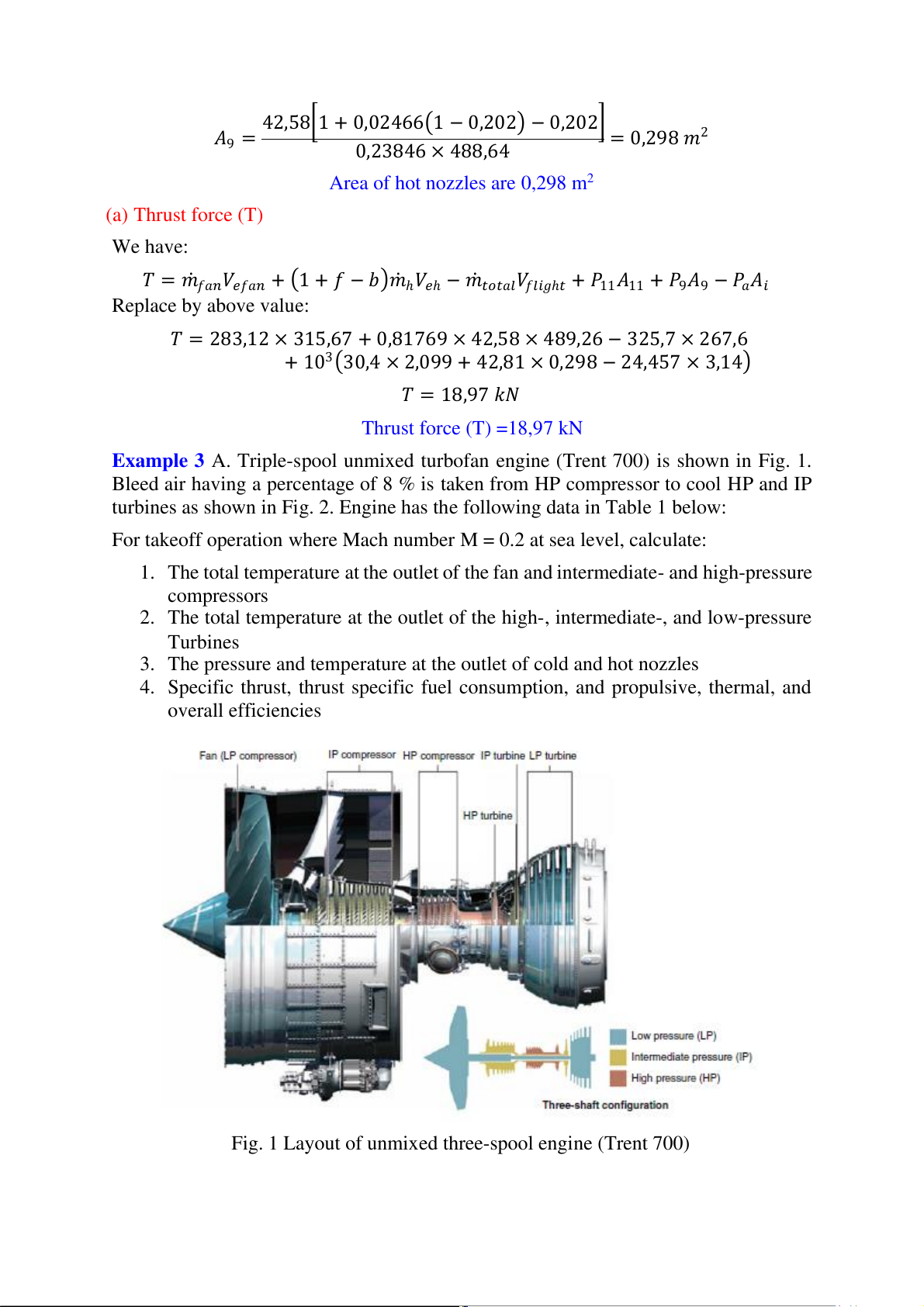
Example 3 A. Triple-spool unmixed turbofan engine (Trent 700) is shown in Fig. 1.
Bleed air having a percentage of 8 % is taken from HP compressor to cool HP and IP
turbines as shown in Fig. 2. Engine has the following data in Table 1 below:
For takeoff operation where Mach number M = 0.2 at sea level, calculate:
1. The total temperature at the outlet of the fan and intermediate- and high-pressure compressors
2. The total temperature at the outlet of the high-, intermediate-, and low-pressure Turbines
3. The pressure and temperature at the outlet of cold and hot nozzles
4. Specific thrust, thrust specific fuel consumption, and propulsive, thermal, and overall efficiencies
Fig. 1 Layout of unmixed three-spool engine (Trent 700)
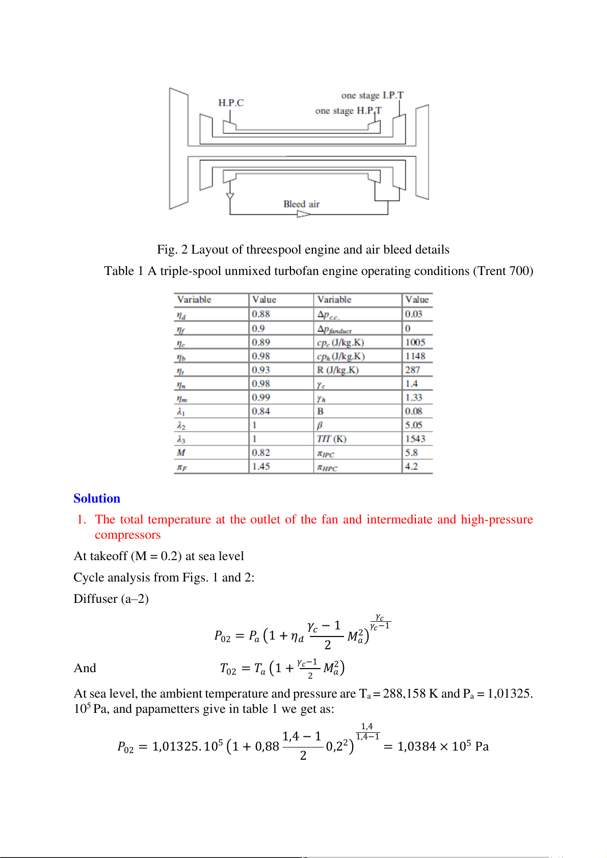
Fig. 2 Layout of threespool engine and air bleed details
Table 1 A triple-spool unmixed turbofan engine operating conditions (Trent 700) Solution
1. The total temperature at the outlet of the fan and intermediate and high-pressure compressors
At takeoff (M = 0.2) at sea level
Cycle analysis from Figs. 1 and 2: Diffuser (a–2) 𝛾 𝛾𝑐 𝛾 𝑃 𝑐 − 1 2 𝑐−1 02 = 𝑃𝑎 (1 + 𝜂𝑑 2 𝑀𝑎) And 𝑇 2
02 = 𝑇𝑎 (1 + 𝛾𝑐−1 𝑀 ) 2 𝑎
At sea level, the ambient temperature and pressure are Ta = 288,158 K and Pa = 1,01325.
105 Pa, and papametters give in table 1 we get as: 1,4 1,4 − 1 1,4−1 𝑃 5 5 02 = 1,01325. 10 (1 + 0,88 2 0,22) = 1,0384 × 10 Pa 1,4 − 1 𝑇02 = 288,16 (1 + 2 0.22) = 290,4653 K Fan (2–3) 𝑃03 = 𝑃02 × 𝜋𝑓 𝛾𝑐−1 𝜋 𝛾𝑐 − 1 𝑇 𝑓 03 = 𝑇02 (1 + 𝜂 ) 𝑓
We have: 𝜂𝑓 = 0,9; 𝜋𝑓 = 1,45; 𝛾𝑐 = 1,4 Replace above vulue we get: 𝑃 5 5
03 = 1,0384 × 10 × 1,45 = 1,5057 × 10 Pa 1,4−1 1,45 1,4 𝑇 − 1 03 = 290,4653 (1 + 0,9 ) = 326,6124 K
Temperature at the outlet of the fan: 𝑇03 = 326,6124 K
Intermediate-pressure compressor (IPC) (3–4)
𝑃04 = 𝑃03 × 𝜋𝐼𝑃𝐶 𝛾𝑐−1 𝜋 𝛾𝑐 − 1 𝑇 𝐼𝑃𝐶 04 = 𝑇03 (1 + 𝜂 ) 𝐼𝑃𝐶
We have: 𝜂𝐼𝑃𝐶 = 0,89; 𝜋𝐼𝑃𝐶 = 5,8; 𝛾𝑐 = 1,4 𝑃 5 5
04 = 1,5057 × 10 × 5,8 = 8,7333 × 10 Pa 1,4−1 5,8 1,4 − 1 𝑇04 = 326,6124 (1 + 0,89 ) = 566,0401 K
Temperature of intermediate pressure compressors: 𝑇04 = 566,0401 K
High-pressure compressor (HPC) (4–5)
We have: 𝜂𝐻𝑃𝐶 = 0,98; 𝜋𝐻𝑃𝐶 = 4,2 ; 𝛾𝑐 = 1,4
Bleed air is extracted at an intermediate state defined as: 𝑃 5 6
04𝑏 = 𝑃04 × √𝜋𝐻𝑃𝐶 = 8,7333 × 10 × √4,2 = 1,7898 × 10 𝛾𝑐−1 1,4−1 𝜋 𝛾𝑐 − 1 1,4 − 1 𝑇 𝐻𝑃𝐶 4,2 04𝑏 = 𝑇04 × (1 + 𝜂 ) = 566,0401 (1 + 710 7556 K 𝐻𝑃𝐶 0,98 ) = ,
Temperature of high pressure compressors: 𝑇04𝑏 = 710,7556 K 𝑃 6 6
05 = 𝑃04𝑏 × √𝜋𝐻𝑃𝐶 = 1,7898 × 10 × √4,2 = 3,668 × 10 𝛾𝑐−1 1,4−1 𝜋 𝛾𝑐 − 1 1,4 𝑇 𝐻𝑃𝐶 4,2 − 1 05 = 𝑇04𝑏 × (1 + 𝜂 ) = 710,7556 (1 + 892 4693 K 𝐻𝑃𝐶 0,98 ) = ,
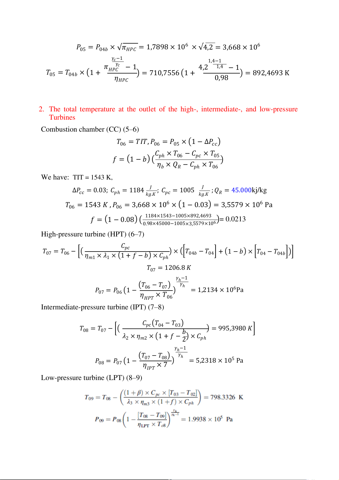
2. The total temperature at the outlet of the high-, intermediate-, and low-pressure Turbines
Combustion chamber (CC) (5–6)
𝑇06 = 𝑇𝐼𝑇, 𝑃06 = 𝑃05 × (1 − ∆𝑃𝑐𝑐) 𝐶
𝑓 = (1 − 𝑏) ( 𝑝ℎ × 𝑇06 − 𝐶𝑝𝑐 × 𝑇05 𝜂 )
𝑏 × 𝑄𝑅 − 𝐶𝑝ℎ × 𝑇06 We have: TIT = 1543 K,
∆𝑃𝑐𝑐 = 0.03; 𝐶𝑝ℎ = 1184 𝐽 ; 𝐶 ; 𝑄 . kj/kg 𝑘𝑔.𝐾 𝑝𝑐 = 1005 𝐽 𝑘𝑔.𝐾 𝑅 = 45 000 𝑇 6 6
06 = 1543 𝐾 , 𝑃06 = 3,668 × 10 × (1 − 0.03) = 3,5579 × 10 Pa
𝑓 = (1 − 0.08) ( 1184×1543−1005×892,4693 )= 0.0213 0.98×45000−100 ×3, 5 5579×106
High-pressure turbine (HPT) (6–7) 𝐶 𝑇 𝑝𝑐 07 = 𝑇06 − [( 𝜂
) × ([𝑇04𝑏 − 𝑇04] + (1 − 𝑏) × [𝑇04 − 𝑇04𝑏])]
𝑚1 × 𝜆1 × (1 + 𝑓 − 𝑏) × 𝐶𝑝ℎ 𝑇07 = 1206.8 𝐾 𝛾 (𝑇 ℎ−1 𝛾 𝑃 06 − 𝑇07) ℎ 6 07 = 𝑃06 (1 − 𝜂 ) = 1,2134 × 10 Pa 𝐻𝑃𝑇 × 𝑇06
Intermediate-pressure turbine (IPT) (7–8) 𝐶 𝑇 𝑝𝑐(𝑇04 − 𝑇03) 08 = 𝑇07 − [( ) = 995,3980 𝐾] 𝜆 𝑏
2 × 𝜂𝑚2 × (1 + 𝑓 − 2) × 𝐶𝑝ℎ 𝛾ℎ−1 (𝑇 𝛾 𝑃 07 − 𝑇08) ℎ 5 08 = 𝑃07 (1 − 𝜂 = 5,2318 × 10 Pa 𝐼𝑃𝑇 × 7 )
Low-pressure turbine (LPT) (8–9)
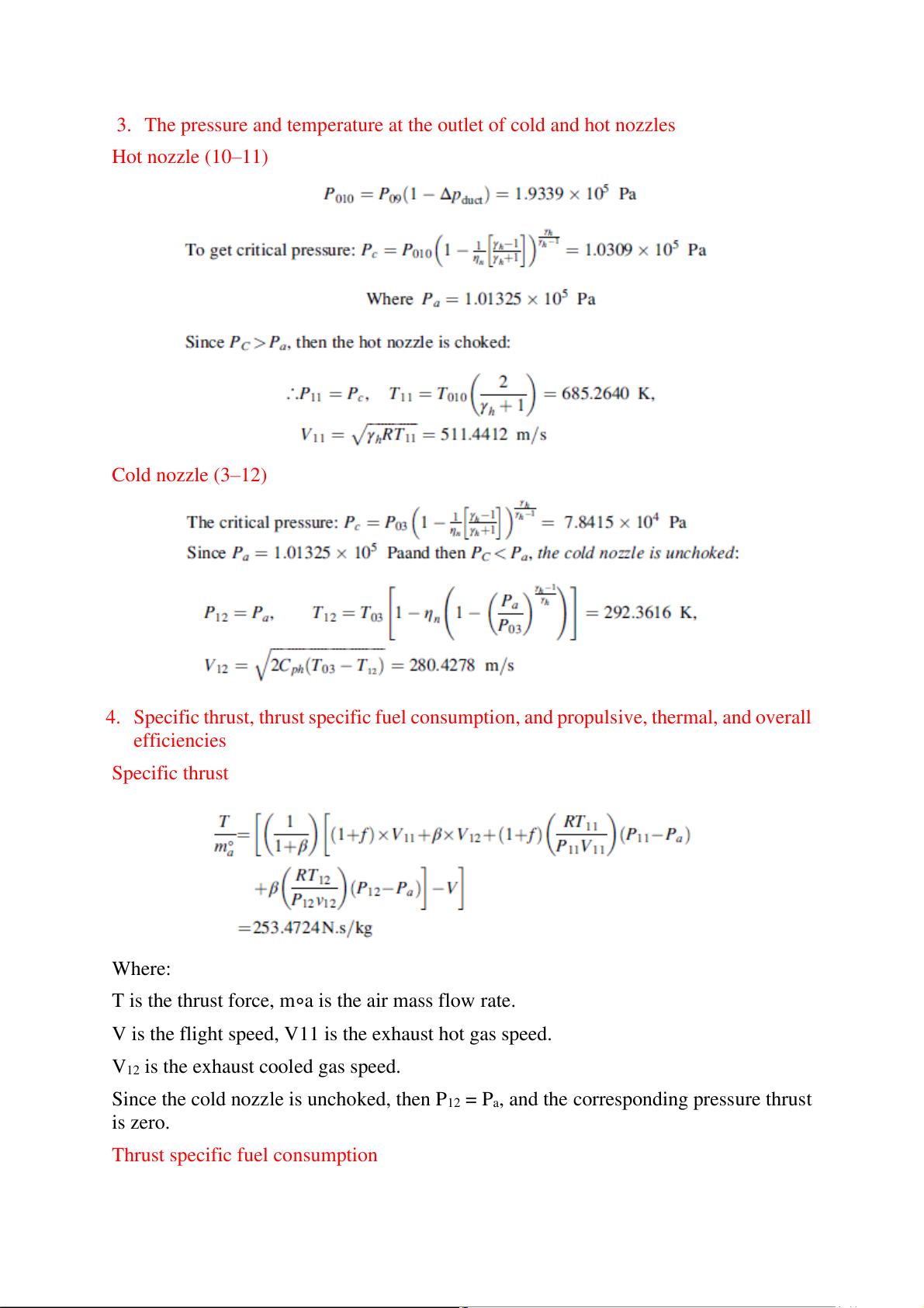
3. The pressure and temperature at the outlet of cold and hot nozzles Hot nozzle (10–11) Cold nozzle (3–12)
4. Specific thrust, thrust specific fuel consumption, and propulsive, thermal, and overall efficiencies Specific thrust Where:
T is the thrust force, m∘a is the air mass flow rate.
V is the flight speed, V11 is the exhaust hot gas speed.
V12 is the exhaust cooled gas speed.
Since the cold nozzle is unchoked, then P12 = Pa, and the corresponding pressure thrust is zero.
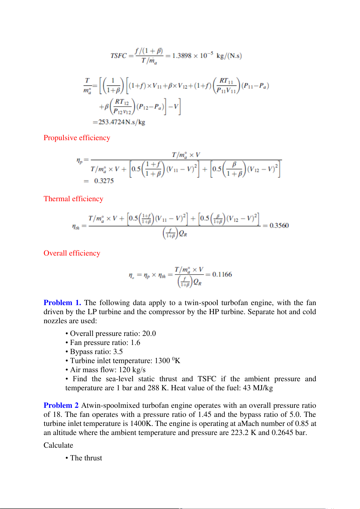
Thrust specific fuel consumption Propulsive efficiency Thermal efficiency Overall efficiency
Problem 1. The following data apply to a twin-spool turbofan engine, with the fan
driven by the LP turbine and the compressor by the HP turbine. Separate hot and cold nozzles are used:
• Overall pressure ratio: 20.0 • Fan pressure ratio: 1.6 • Bypass ratio: 3.5
• Turbine inlet temperature: 1300 0K • Air mass flow: 120 kg/s
• Find the sea-level static thrust and TSFC if the ambient pressure and
temperature are 1 bar and 288 K. Heat value of the fuel: 43 MJ/kg
Problem 2 Atwin-spoolmixed turbofan engine operates with an overall pressure ratio
of 18. The fan operates with a pressure ratio of 1.45 and the bypass ratio of 5.0. The
turbine inlet temperature is 1400K. The engine is operating at aMach number of 0.85 at
an altitude where the ambient temperature and pressure are 223.2 K and 0.2645 bar. Calculate • The thrust • TSFC • Propulsive efficiency
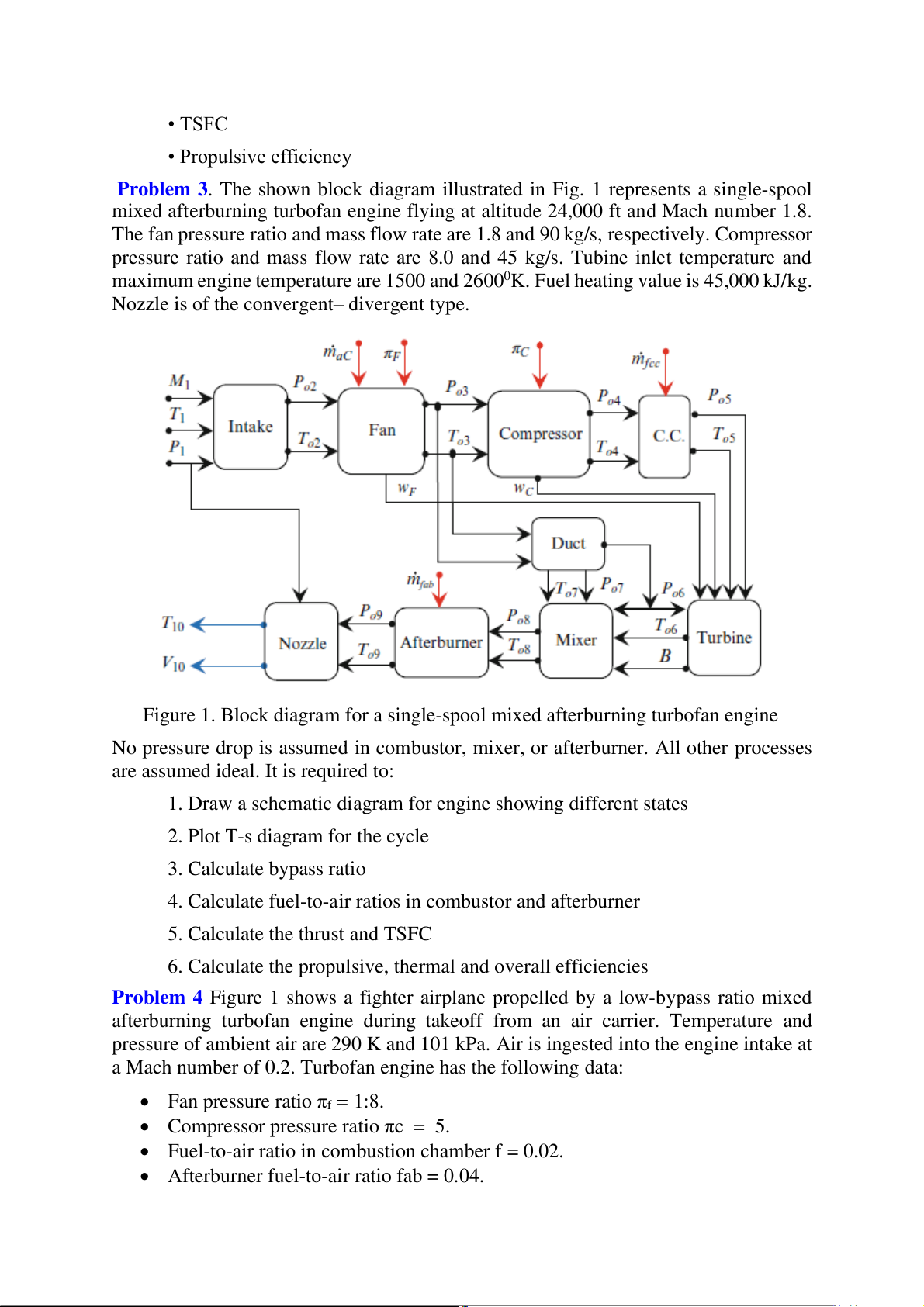
Problem 3. The shown block diagram illustrated in Fig. 1 represents a single-spool
mixed afterburning turbofan engine flying at altitude 24,000 ft and Mach number 1.8.
The fan pressure ratio and mass flow rate are 1.8 and 90 kg/s, respectively. Compressor
pressure ratio and mass flow rate are 8.0 and 45 kg/s. Tubine inlet temperature and
maximum engine temperature are 1500 and 26000K. Fuel heating value is 45,000 kJ/kg.
Nozzle is of the convergent– divergent type.
Figure 1. Block diagram for a single-spool mixed afterburning turbofan engine
No pressure drop is assumed in combustor, mixer, or afterburner. All other processes
are assumed ideal. It is required to:
1. Draw a schematic diagram for engine showing different states
2. Plot T-s diagram for the cycle 3. Calculate bypass ratio
4. Calculate fuel-to-air ratios in combustor and afterburner
5. Calculate the thrust and TSFC
6. Calculate the propulsive, thermal and overall efficiencies
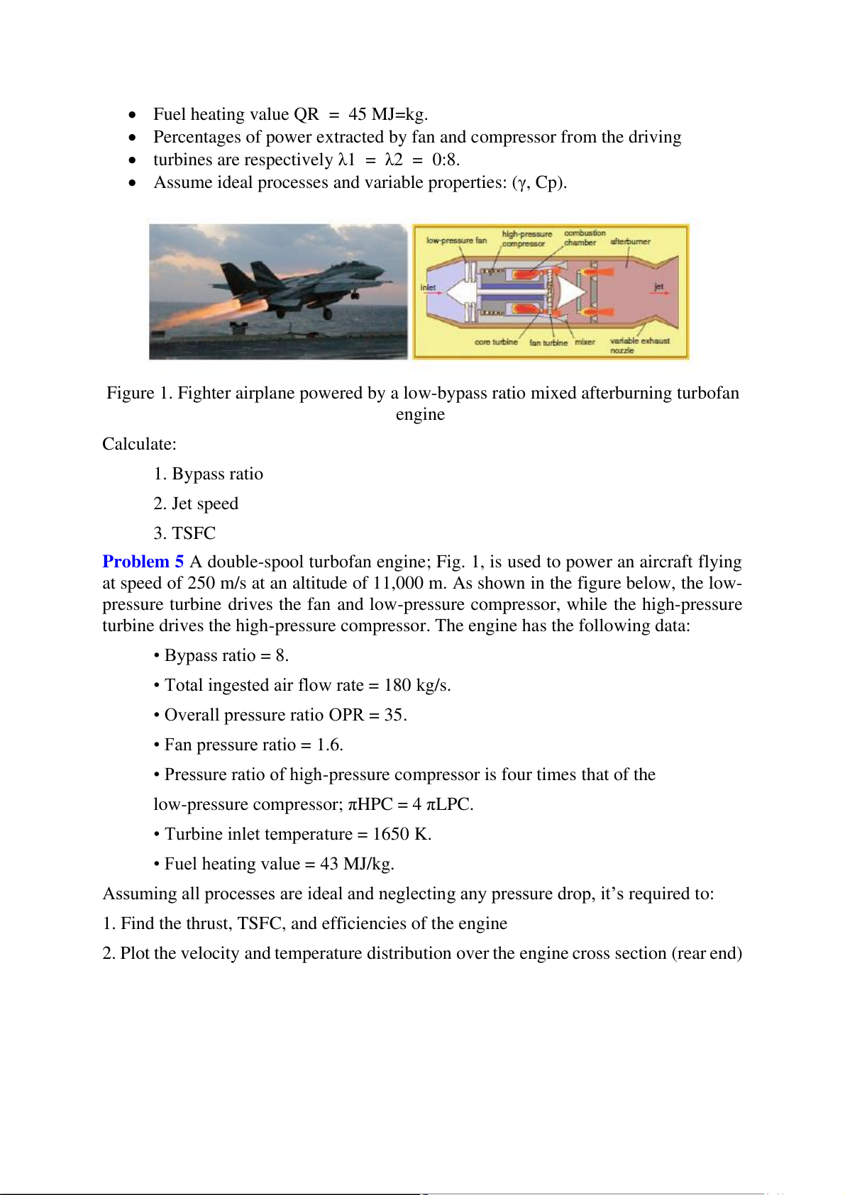
Problem 4 Figure 1 shows a fighter airplane propelled by a low-bypass ratio mixed
afterburning turbofan engine during takeoff from an air carrier. Temperature and
pressure of ambient air are 290 K and 101 kPa. Air is ingested into the engine intake at
a Mach number of 0.2. Turbofan engine has the following data:
• Fan pressure ratio πf = 1:8.
• Compressor pressure ratio πc = 5.
• Fuel-to-air ratio in combustion chamber f = 0.02.
• Afterburner fuel-to-air ratio fab = 0.04.
• Fuel heating value QR = 45 MJ=kg.
• Percentages of power extracted by fan and compressor from the driving
• turbines are respectively λ1 = λ2 = 0:8.
• Assume ideal processes and variable properties: (γ, Cp).
Figure 1. Fighter airplane powered by a low-bypass ratio mixed afterburning turbofan engine Calculate: 1. Bypass ratio 2. Jet speed 3. TSFC
Problem 5 A double-spool turbofan engine; Fig. 1, is used to power an aircraft flying
at speed of 250 m/s at an altitude of 11,000 m. As shown in the figure below, the low-
pressure turbine drives the fan and low-pressure compressor, while the high-pressure
turbine drives the high-pressure compressor. The engine has the following data: • Bypass ratio = 8.
• Total ingested air flow rate = 180 kg/s.
• Overall pressure ratio OPR = 35. • Fan pressure ratio = 1.6.
• Pressure ratio of high-pressure compressor is four times that of the
low-pressure compressor; πHPC = 4 πLPC.
• Turbine inlet temperature = 1650 K.
• Fuel heating value = 43 MJ/kg.
Assuming all processes are ideal and neglecting any pressure drop, it’s required to:
1. Find the thrust, TSFC, and efficiencies of the engine
2. Plot the velocity and temperature distribution over the engine cross section (rear end)
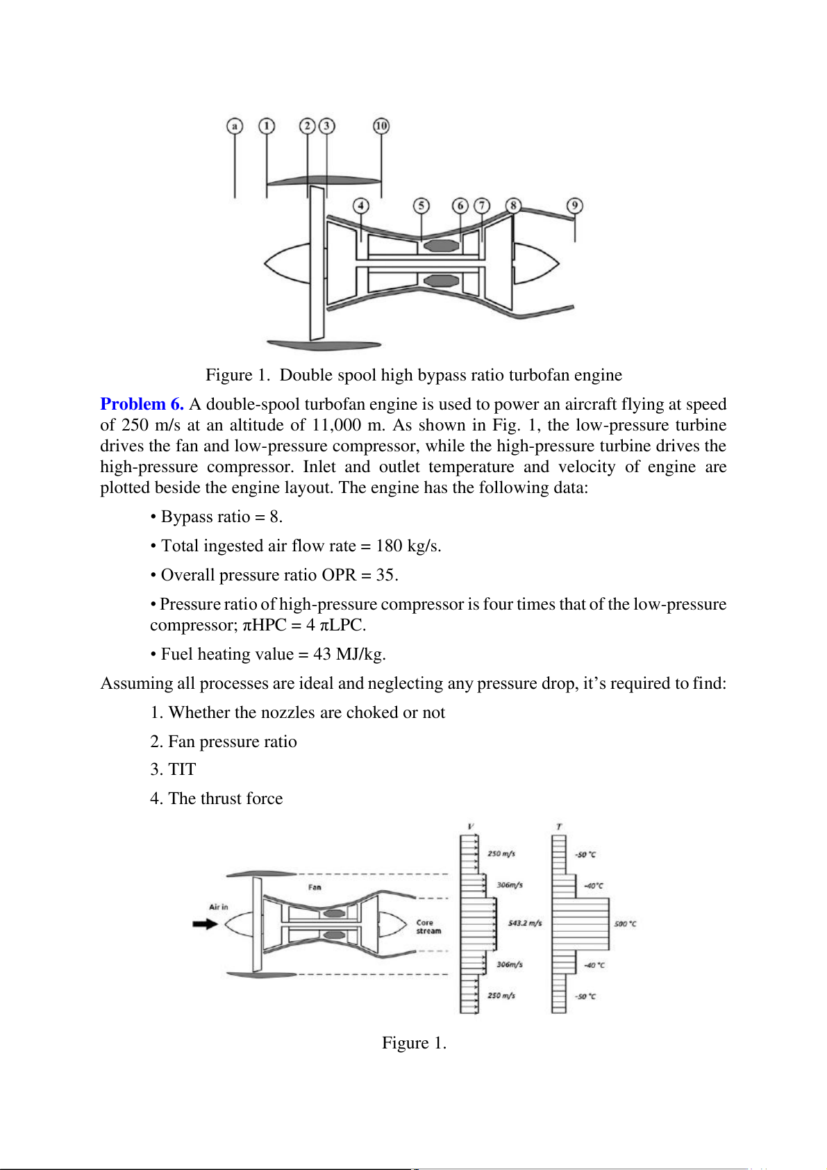
Figure 1. Double spool high bypass ratio turbofan engine
Problem 6. A double-spool turbofan engine is used to power an aircraft flying at speed
of 250 m/s at an altitude of 11,000 m. As shown in Fig. 1, the low-pressure turbine
drives the fan and low-pressure compressor, while the high-pressure turbine drives the
high-pressure compressor. Inlet and outlet temperature and velocity of engine are
plotted beside the engine layout. The engine has the following data: • Bypass ratio = 8.
• Total ingested air flow rate = 180 kg/s.
• Overall pressure ratio OPR = 35.
• Pressure ratio of high-pressure compressor is four times that of the low-pressure compressor; πHPC = 4 πLPC.
• Fuel heating value = 43 MJ/kg.
Assuming all processes are ideal and neglecting any pressure drop, it’s required to find:
1. Whether the nozzles are choked or not 2. Fan pressure ratio 3. TIT 4. The thrust force Figure 1.
Tài liệu liên quan:
-
Áp suất và Lưu lượng Bơm trong Hệ Thống | Cơ sở thủy khí ứng dụng | Trường Đại học Khoa học Tự nhiên, Đại học Quốc gia Hà Nội
63 32 -
Bài tập cơ thuỷ khí | Cơ sở thủy khí ứng dụng | Trường Đại học Khoa học Tự nhiên, Đại học Quốc gia Hà Nội
57 29 -
Hệ Thống Khiển Thủy Lực - Nghiên Cứu và Ứng Dụng | Cơ sở thủy khí ứng dụng | Trường Đại học Khoa học Tự nhiên, Đại học Quốc gia Hà Nội
158 79 -
Hệ Thống Khí Nén - Lịch Sử và Ứng Dụng trong Cơ Học Thủy Khí | Cơ sở thủy khí ứng dụng | Trường Đại học Khoa học Tự nhiên, Đại học Quốc gia Hà Nội
61 31