Experiment 2 - Measurement of Magnetic Field in Finite Solenoid môn Vật lý đại cương 2 | Học viện Công Nghệ Bưu Chính Viễn Thông
According to the Biot-Savard-Laplace’s law, magnetic fieldBr produced on the axis of a current-carrying loop (Fig. 1) is determined as follows. Tài liệu giúp bạn tham khảo, ôn tập và đạt kết quả cao. Mời đọc đón xem!
Môn: Vật lý đại cương 2 298 tài liệu
Trường: Học viện Công Nghệ Bưu Chính Viễn Thông 1.7 K tài liệu
Tác giả:


Preview text:
Experiment 2
Measurement of magnetic field inside a solenoid with finite length 1. Background r
According to the Biot-Savard-Laplace’s law, magnetic field B produced on the axis of a
current-carrying loop (Fig. 1) is determined as follows: μ μ γ μ μ μ μ Br π = ∫ I sin dl π = ∫ IR = IR (1) 2 R 2 R π π 2 dl r 0 r 0 0. 4r r 4 r 2 2 3 3 0 0
Fig.1. Magnetic field produced on the axis of a current-carrying coil.
A solenoid consists of a helical winding of wire on a cylinder, usually circular in cross section.
There can be hundreds or thousands of closely spaced turns, each of which can be regarded as a
circular loop (Fig.2a). Inside solenoid, the field lines are considered to be uniformly spaced as shown in Fig.2b. n n t t u u r r n n s s o o f f ww ir ir e e Br = const (a) (b)
Fig.2. Typical solenoid (a) and magnetic field lines produced by the currents in it (b)
Exact calculations for a long, closely wound solenoid, half of these field lines emerge from the
ends and half ''leak out" through the windings between the center and the ends. Because all
turns carry the same current I. then, the total B field at every point is the vector sum of the fields
caused by the individual turns. For a unit of length of solenoid ds with n turns (Fig.3), we have: μ μ 0 R2 I n ds dB . . r.= (2) 23 r γ d
It can be seen that s = R.cotgγ or ds = +2R and sinγ γ = R/r sin
Fig.3. The way to calculate the magnetic field at a point inside a finite solenoid μ μ Hence: dB. 0 r.s =in + I n γdγ 2
Using Ampere's law, the magnetic field B produced by a finite solenoid with length L at
point A as shown in Fig.3 would be: γ2 μ μ μ μ 0 . . sin 0 γ γ γ γ r B r I n (3) d = ∫In 0 . (cos cos ) = − 0 1 22 γ 2 1 n
where n=0is number of turns per unit length. Lr
For a solenoid with infinitely length, i.e., γ1 = 0, γ2 = π, the magnetic filed becomes: B = μ0.μr.I.n0 (4)
It can be seen that magnetic field produced by a finite coil is smaller than that by an
infinite one. Clearly, the magnetic field inside is homogeneous and its strength does not
depend on the distance from the axis. This last result, which holds strictly true only near
the centre of the solenoid where the field lines are parallel to its length, is most important. 2. Experiment 2.1 Experimental apparatus
The equipments used for the measurement are shown in Fig.4. The current from the DC
power supply flows through a rheostat then through the solenoid. The rheostat is used to
monitor the magnitude of current, which is read out with an ammeter. The axial
magnetic-induction probe inside solenoid measures the component of the magnetic field
along the solenoid symmetry axis. The axial probe can be moved easily along the
solenoid. The position of the probe is determined using a linear rule attached with the
probe. The magnetic field is read out with the Teslameter. Te T s e l s a l m a e m t e e t r Rh R e h o e s o t s a t t er a Po P w o e w r e r su s p u p p l p i l e i r e In I f n i f n i i n t i e t e l o l n o g n g s o s l o e l n e o n i o d i Am A m m e m t e er e Fig.4. Experimental apparatus 2.2 Preparation
- Using wires to connect the solenoid, rheostat and ammeter together in series following
the circuit shown in figure 5.
- Check if the axial probe had connected with Teslameter. Te T s e l s a l a M e M t e e t r e 1 2. 5 VC V - C 8 - 6 8 0 6 6 0 A R Ra R n a g n e g K ~U ~ U ( 5 ( 0 5 0 H z H ) z
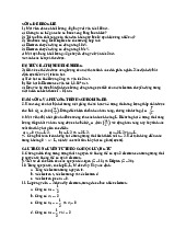
Fig.5. Layout of measurement circuit 2.3 Experimental Procedure
There are three measurements you should make.
a) Investigation of the magnetic field at the positions along the axis of solenoid - B(x)
1. Place the axial probe so that one end of solenoid is corresponding to the position 0 of
the linear rule attached with the probe.
2. Set the voltage of power supply to 3 V.
3. Turn on the solenoid power supply and Teslameter. Record the initial value of current
shown on ammeter and magnetic field shown on Teslameter.
4. Measure the relationship B(x) by slowly moving the axial probe every 1 cm between 0 to 30cm.
Make a data table (denoted table 1) then record the corresponding values of position x
and magnetic field shown on Teslameter in it.
b) Measurement of the relationship between the magnetic field and the current through the solenoid - B(I)
1. Place and fix the axial probe at the center of the coil (corresponding to the position of x = 15 cm).
2. Measure the relationship B(I) for several values of power supply from 3V up to 12V.
Make a data table (denoted table 2) then record the values of current I shown on
Ampermeter and magnetic field shown on Tesla-meter in this table corresponding to the different positions.
c) Comparison of experimental and theoretical magnetic field
1. Varying the rheostat so that the value of current shown on ammeter is 0.4 A, then fix this current.
2. Make a data table (denoted table 3) then record the values of the magnetic field shown
on Tesla-meter in this table corresponding to the different positions axial probe at 0 cm, 15 cm and 30 cm in it.
Tài liệu liên quan:
-
Bài tập Vật lý nguyên tử môn Vật lý đại cương 2 | Học viện Công Nghệ Bưu Chính Viễn Thông
11 6 -
Bài tập Vật lý nguyên tử môn Vật lý đại cương 2 | Học viện Công Nghệ Bưu Chính Viễn Thông
12 6 -

Tán xạ ánh sáng và Hiệu ứng Tyndall - Lý thuyết và Ứng dụng môn Vật lý đại cương 2 | Học viện Công Nghệ Bưu Chính Viễn Thông
19 10 -

Chương 23: Quang học lượng tử môn Vật lý đại cương 2 | Học viện Công Nghệ Bưu Chính Viễn Thông
17 9 -

Chương 24: Cơ Học Lượng Tử - Tính Sóng-Hạt và Phương Trình Schrödinger môn Vật lý đại cương 2 | Học viện Công Nghệ Bưu Chính Viễn Thông
18 9