Experiment 3 investigation of electric oscillation of rl and rlc circuits môn Vật lý đại cương 2 | Học viện Công Nghệ Bưu Chính Viễn Thông
Understanding the current across an inductor-resistor and the RLCcircuits, then calculate the energy of the oscillation RLC circuit .Tài liệu giúp bạn tham khảo, ôn tập và đạt kết quả cao. Mời đọc đón xem!
Môn: Vật lý đại cương 2 298 tài liệu
Trường: Học viện Công Nghệ Bưu Chính Viễn Thông 1.7 K tài liệu
Tác giả:


Preview text:
EXPERIMENT 3
Investigation of Electric Oscillation of RL and RLC Circuits Equipment and Materials
Science Workshop 750 Interface Power Amplifier
Lab circuit board with available inductor coil Iron rod for coil core Capacitor of 10 μF Objectives
Understanding the current across an inductor-resistor and the RLC circuits, then calculate the
energy of the oscillation RLC circuit.
How to process the experimental results
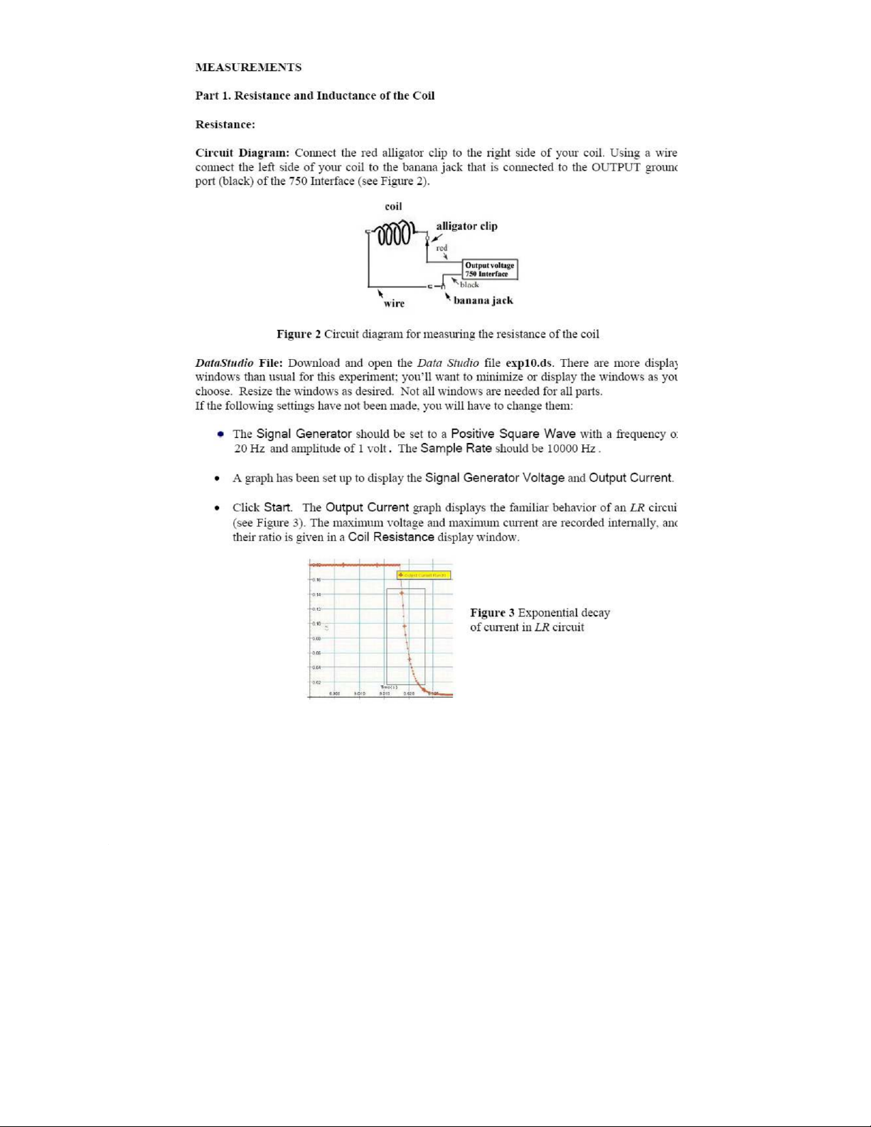
Part 1. Resistance and Inductance of the Coil
Question 1: Measure and calculate the resistance RL of your coil L.
Question 2: Calculate the inductance of your coil with and without the iron core based on the value
of slope obtained by Datastudio software.
Coil inductance without core: Lw/o = mH
Coil inductance with core: Lw = mH
Part 2: Free Oscillations of the RLC circuit
Question 3: Calculate the frequency, fmeasured = 1/T (Hz) based on the period of oscillation
determined by tools of Datastudio software. 1
Question 4: For your circuit parameters, compute the expected value of fprediction =( L H C z) π 2
and compare it to your measured value. Do you expect your result to be greater, equal, or less than
the measured value (Δf = prediction − fmeasured )?
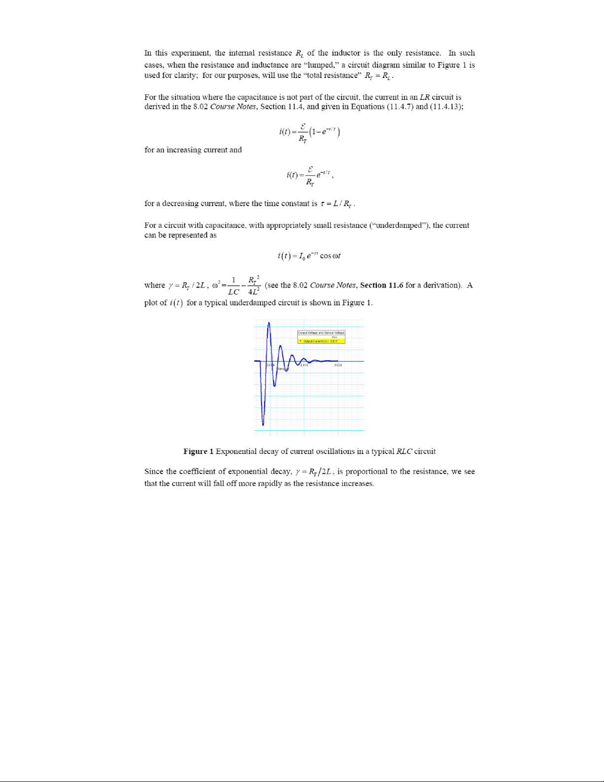
Part 3: Observe the Energy in the RLC Circuit
Question 5: The circuit is losing energy most rapidly at times when the graph of total energy is
steepest; these times occur at about the same times that the magnetic energy reaches a local maximum. Briefly explain why.
Tài liệu liên quan:
-
Bài tập Vật lý nguyên tử môn Vật lý đại cương 2 | Học viện Công Nghệ Bưu Chính Viễn Thông
11 6 -
Bài tập Vật lý nguyên tử môn Vật lý đại cương 2 | Học viện Công Nghệ Bưu Chính Viễn Thông
12 6 -

Tán xạ ánh sáng và Hiệu ứng Tyndall - Lý thuyết và Ứng dụng môn Vật lý đại cương 2 | Học viện Công Nghệ Bưu Chính Viễn Thông
20 10 -

Chương 23: Quang học lượng tử môn Vật lý đại cương 2 | Học viện Công Nghệ Bưu Chính Viễn Thông
18 9 -

Chương 24: Cơ Học Lượng Tử - Tính Sóng-Hạt và Phương Trình Schrödinger môn Vật lý đại cương 2 | Học viện Công Nghệ Bưu Chính Viễn Thông
19 10