Experiment 5 Investigation of transmission of electromagnetic wave (microwave) môn Vật lý đại cương 2 | Học viện Công Nghệ Bưu Chính Viễn Thông
Evaluate qualitative and quantitative results of transmitting andreceiving microwave. Tài liệu giúp bạn tham khảo, ôn tập và đạt kết quả cao. Mời đọc đón xem!
Môn: Vật lý đại cương 2 298 tài liệu
Trường: Học viện Công Nghệ Bưu Chính Viễn Thông 1.7 K tài liệu
Tác giả:

Preview text:
EXPERIMENT 5
INVESTIGATION OF TRANSMISSION OF ELECTROMAGNETIC WAVE (MICROWAVE) I. Purpose of experiment:
- Evaluate qualitative and quantitative results of transmitting and receiving microwave
- The experiment involces investigating various phenomena related to microwave: straight
line propagation, penetration, screening and absorption, reflection, refraction, diffraction,
polarization and wavelength of standing waves.
II. Experiment results and conclusions
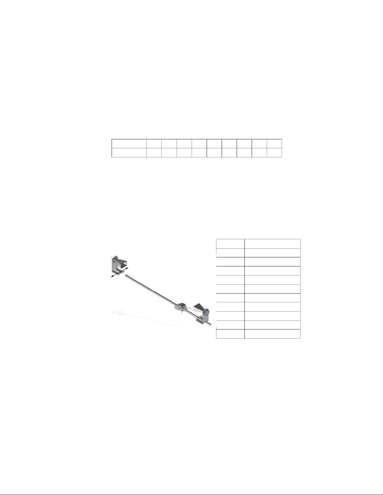
1. Straight-line propagation of microwaves 1.1. Moving the receiver away. a) Experiment procedure
- Set up the transmitter and receiver facing one another with the receiver off the
- Increase the distance l from 20cm to 60cm. Record the voltmeter value every 5cm
- Observe and make conclusions. b) Observation l (cm) 20 25 30 35 40 45 50 55 60 Voltage (V)
7.41 5.58 4.43 2.97 2.16 1.39 0.98 0.79 0.76
The value of the voltmeter decrease regarding the increment of distance between transmitter and receiver. c) Conclusion
Microwaves are a form of electromagnetic radiation that spreads out as it travels
the transmitter. As the signal energy spreads, the intensity of the signal reaching receiver drops rapidly.
1.2. Changing the angle of transmitter and receiver.
a) Experiment procedure and results
- Set up the transmitter and receiver facing one another with the receiver off the - Increase the angle α
of the receiver and the rail from 0 o to 90 ,o record the vo every 10 .o l = 30(cm) α Voltage V(V) 0 1.75 o 10o1.71 20o0.98 30o0.38 40o0.020 50o0.013 60o0.013 70o0.013 80o0.013 90o0.013 b) Observation:
- When the receiver is aligned with the rail (the transmitter and receiver are facing
other), the volt-meter shows the maximum value
- When angle between the angle and the rail increases, the value of volt-meter decr c) Conclusion:
- Microwave propagates best in straight line.
2. Screening and absorbtion of microwaves
a) Experiment procedure and results
- Set up the transmitter and the receiver facing one another.
- Place the reflection plate between the transmitter and receiver.
- Set the amplification to medium level. Observe and make conclusion.
- Replace the reflection plate with the
absorbtion plate. Observer and make conclusion Plate Nothing
Reflection plate Absorbtion plate Voltage 1.41 (V) 0.001 (V) 0.79 (V) b) Observation
- When a reflection plate (made of conducting material) is put between transmitter
and receiver, the volt-meter shows a small value (0.001(V) which is approximately
compare to the absorbtion plate case. c) Conclusion
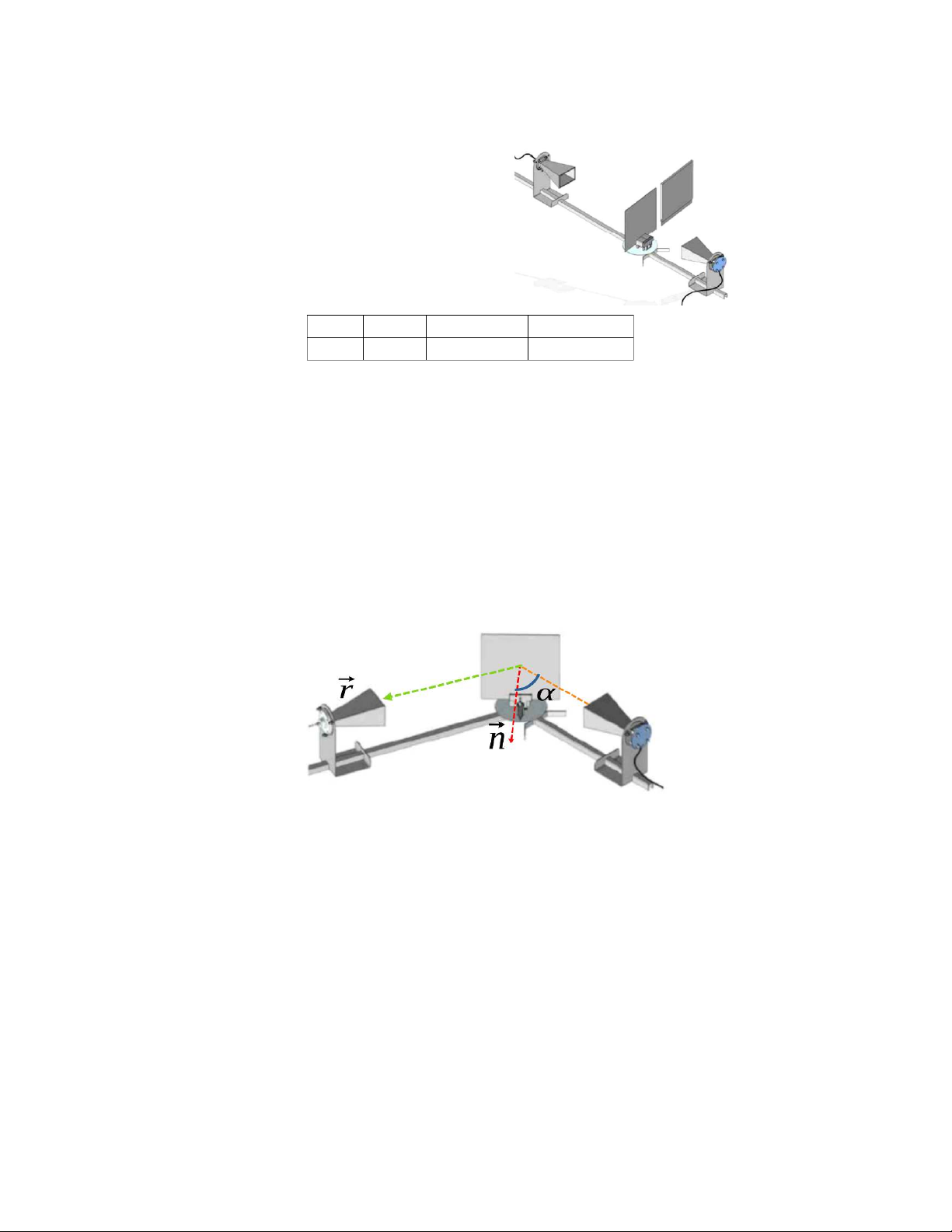
- Most of microwave cannot go through conducting material. 3. Reflection of microwaves
a) Experiment procedure and results
- Set up the transmitter and receiver at an angle of incidence to be read off.
- Line up the reflector plate at angle of approximately 30° with the help of the
for the rails, which points in the direction of the normal (a line perpendicular to mirror’s surface).
- Change the angle of the long rail until the maximum reception is attained. Mea
angles of incidence from the normal (arrow) and make conclusion. b) Observation α=30o Angle between receiver and normal vector of the plate
Voltage (reflection plate) Voltage (absorbtion plate) (r, n) 10o0.67 (V) 0.021 (V) 20o1.68 (V) 0.31 (V) 30o3.12 (V) 0.46 (V) 40o2.47 (V) 0.11 (V) 50o1.01 (V) 0.046 (V) 60o0.30 (V) 0.028 (V) 70o0.043 (V) 0.018 (V) 80o0.035 (V) 0.015 (V) 90o0.025 (V) 0.017 (V)
When the normal vector of the plate (the pointer) is the bisector of 2 rails (th
reflecting angle is equal to angle between receiver and the plate’s normal vector), voltmeter shows maximum value. c) Conclusion
- Microwave reflects best when normal vector of the reflection plate is the bisecto
an angle created by the transmitter and receiver.
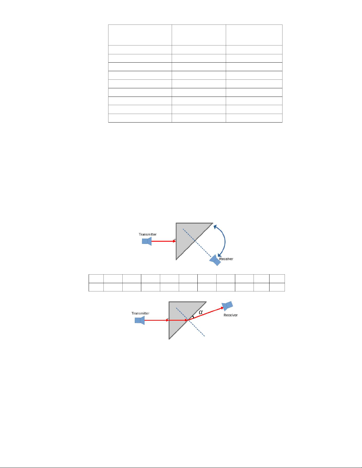
- When microwaves reflects, the angle of incidence equals the angle of reflection. 4. Refraction of microwaves a) Experiment procedure
- Set up the transmitter to face perpendicular to the small side of prism, the big the prism facing receiver.
- Turn the long rail until the maximum reception is attained. Observe and make
conclusion of the reception of a signal. b) Observation α 90 80 o 70 o 60 o 50 o 40 o 30 o 20 o 10 o 0 o o Volt
0.028 0.021 0.032 0.023 0.019 0.036 0.070 0.051 0.65 0.43
When the angle between the receiver and the prism big plane is 10 ,o the voltage is c) Conclusion - Microwaves obey refraction.
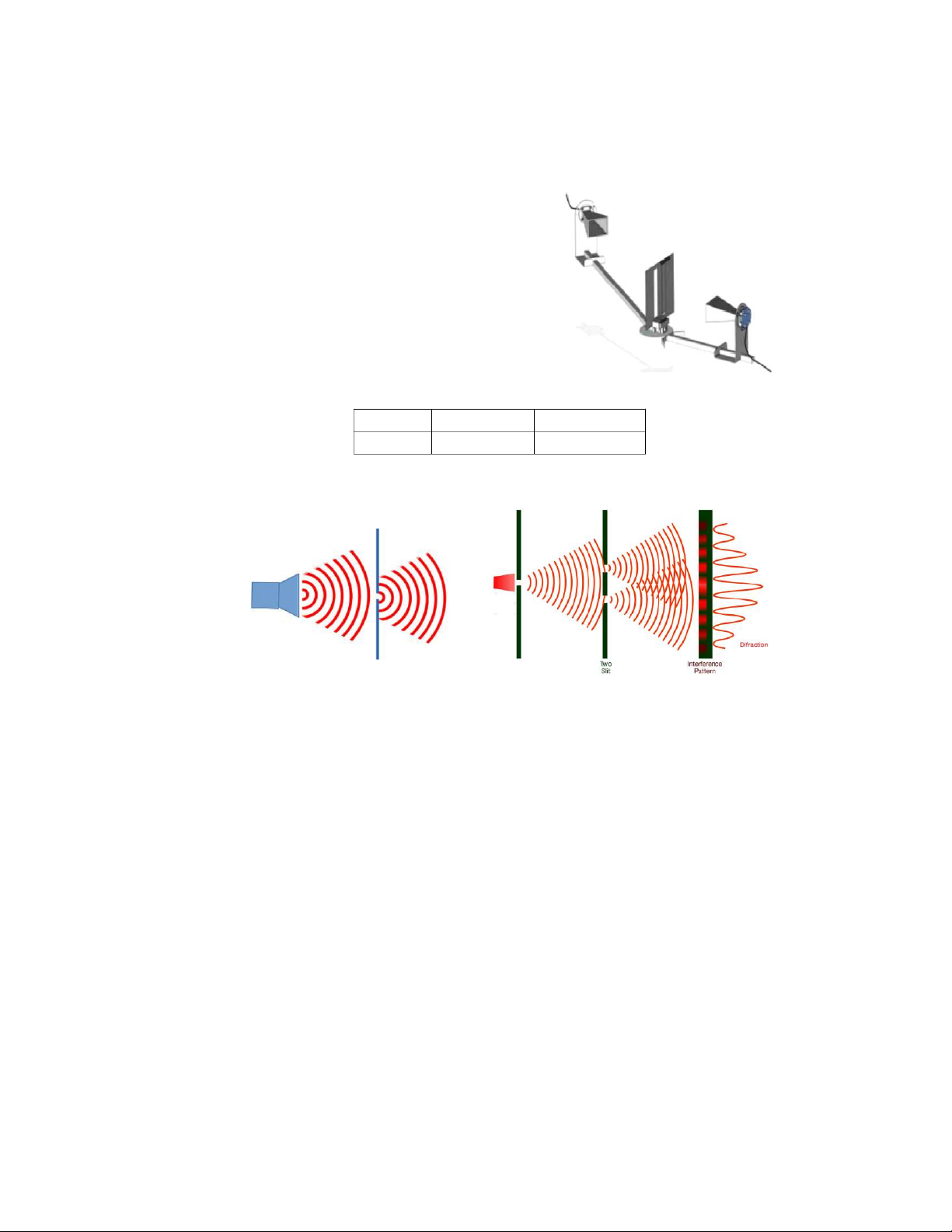
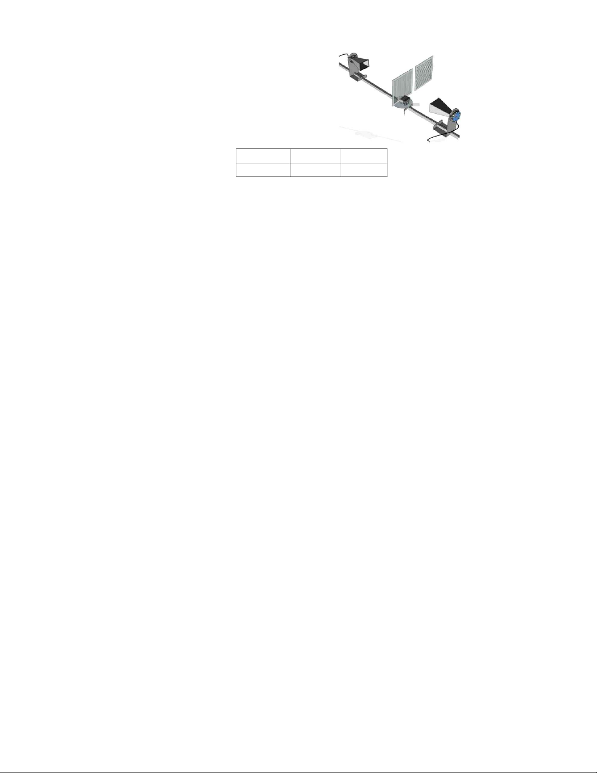
- Microwaves follow the same laws of geometrical optics as visible light, specifica the law of refraction. 5. Diffraction of microwaves a) Experiment procedure
- Set up the accessories including transmitter and
receiver directly facing each other about 80 cm apart.
- Place single-slit plate (width of slit is smaller
than the wavelength) so that it is vertically aligned
about 20 cm in front of the transmitter in such a
way that the receiver once more detects a signal.
- Observe and make a conclusion of the reception
of a signal if microwaves were diffracted by the
slit that wavelets could be detected in the shadow of the aperture.
- Replace the 1 slit plate with 2 slits plate. Observe and make conclusions b) Observation Plate 1 slit plate 2 slits plate Voltage 0.43 (V) 0.89(V)
The observation that the voltage recorded with two slits (0.89 V) is nearly double
compare to the voltage recorded with one slit (0.43 V). This is primarily due to the
phenomena of diffraction and interference of the microwave waves. one slit
- Single Slit case: Diffraction is the process that allows the wave to spread out the plate.
- Double Slit case: The wave diffracts through both slits, and the two resulting
wavefronts interfere with each other. At the location of the detector, the measured
signal is the result of this interference, often showing a much higher voltage due constructive interference. c) Conclusion:
- Microwaves have diffraction properties. 6. Polarization of microwaves a) Experiment procedure
- Set up the polarisation grating in the screen holder.
- Check the reception when the polarization
grating is aligned horizontally and vertically.
Make the conclusions of receiver’s signal and
explanations of experimental results in two cases. b) Observation Orientation Horizontal Vertical Voltage 0.83 (V) 0.037 (V)
When the grating is aligned horizontally, the value on the voltmeter is slightly decre
When the grating is aligned vertically, the value on the voltmeter is nearly zero. c) Conclusion
- The wave passes through the horizontal gaps with minimal interaction. Most signal passes through.
- The vertical gaps absorb/reflect nearly all the microwave energy. Very little signal passes through.
Tài liệu liên quan:
-
Bài tập Vật lý nguyên tử môn Vật lý đại cương 2 | Học viện Công Nghệ Bưu Chính Viễn Thông
11 6 -
Bài tập Vật lý nguyên tử môn Vật lý đại cương 2 | Học viện Công Nghệ Bưu Chính Viễn Thông
12 6 -

Tán xạ ánh sáng và Hiệu ứng Tyndall - Lý thuyết và Ứng dụng môn Vật lý đại cương 2 | Học viện Công Nghệ Bưu Chính Viễn Thông
20 10 -

Chương 23: Quang học lượng tử môn Vật lý đại cương 2 | Học viện Công Nghệ Bưu Chính Viễn Thông
18 9 -

Chương 24: Cơ Học Lượng Tử - Tính Sóng-Hạt và Phương Trình Schrödinger môn Vật lý đại cương 2 | Học viện Công Nghệ Bưu Chính Viễn Thông
19 10