Experiment report 1 Measurement of resistance, capacitence, Inductance and resonant frequencies of rlc using Oscilloscope môn Vật lý đại cương 2 | Học viện Công Nghệ Bưu Chính Viễn Thông
The theoretical result of resonant frequency is approximately equal tothe directly measured results . Tài liệu giúp bạn tham khảo, ôn tập và đạt kết quả cao. Mời đọc đón xem!
Môn: Vật lý đại cương 2 298 tài liệu
Trường: Học viện Công Nghệ Bưu Chính Viễn Thông 1.7 K tài liệu
Tác giả:


Preview text:
Experiment Report 1
MEASUREMENT OF RESISTANCE, CAPACITENCE,
INDUCTANCE AND RESONANT FREQUENCIES OF RLC USING OSCILLOSCOPE
Verification of the instructors
Name: Nguyễn Nhật Minh Group: 04 Student ID: 20224347
I. EXPERIMENT MOTIVATIONS -Understand a typical circuit
-Learn how to use electrical equipment including oscilloscope and function generator
-Improving experimental skills. II. EXPERIMENT RESULTS.
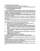
1.Resistance Measurement: Trial f (Hz) R(Ω) 11000 2022 22000 2025 33000 2026
2.Capacitance Measurement: Trial f (Hz) R (Ω) 11000 2403 22000 1186 33000 804
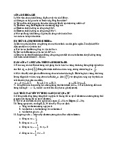
3.Inductance Measurement Trial f (Hz) R (Ω) 110000 56 220000 107 330000 166
4.Determination of Resonant Frequency: Trial Series RLC Parallel RLC 122699 (Hz) 22704 (Hz) 223004 (Hz) 23002 (Hz) 323114 (Hz) 23105 (Hz) II. Data Analysis:
1.Resistance Measurement: We have RX=R0 3 ∑ Ri i=1 Rx= 3=2024(Ω)
√3∑(Rxi−Rx)2 ΔR i=1 x≈S. D ≈ 3=1(Ω) Hence:
Rx=2024±1(Ω)
2.Capacitence Measurement: Zx=1 =R0 hence CX=1 2πfCx 2πfR0
C1=6.62×10⁻⁸(F) ; C2=6.71×10⁻⁸(F) ; C3=6.60×10⁻⁸(F) 3 ∑ Cxi C i=1 X=
3=6.64×10⁻⁸(F) 3
Δ CX≈ S. D≈ √∑¿¿¿¿¿ i=1 Hence:
CX= (6.64±0.03 )×10−8(F)
3.Inductance Measurement: L Z x=R0
L=2πf .Lx=R0 hence 2πf We have:
L1=8.9×10⁻⁴(H)
L2=8.5×10⁻⁴(H)
L3=8.9×10⁻⁴(H) 3 ∑ Lxi i=1 L 3=8.7 x= ×10−4(H)
√3∑(Lxi−Lx)2 i=1 ΔL 3=0.1 x≈ S. D ≈ ×10−4(H) Hence:
LX=( 8.7±0.1)×10−4(H)
4.Determination of Resonant Frequency:
a. Series RLC Circuit: 3 ∑ fxi i=1 fx= 3=22936(Hz) √3∑(f Xi−fX)2 i=1 Δf x≈ S .D ≈ 3=99(Hz) Hence:
fX−Series=fx+Δfx=
(22,936±0.1 ).103(Hz)
b.Parallel RLC Circuit: 3 ∑ fxi f i=1 X= 3=22937(Hz)
√3∑(fXi−fX )2 i=1 Δf X≈ S. D ≈ 3=98(Hz) Hence:
fX−¿=fx+Δfx=
(22,937±0.1 ).103(Hz)❑
c.Theoretical Result and Conclusion f=1 2π √LC fX=1
8.7×10−4×6.64×10−8=20940(Hz) 2π √ Hence:
fX−T heoretical=20940 (Hz) We can see that:
The theoretical result of resonant frequency is approximately equal to the
directly measured results. We can see that the RLC circuit (with properly
small resistance) becomes a good approximation to an ideal LC circuit.
Tài liệu liên quan:
-
Bài tập Vật lý nguyên tử môn Vật lý đại cương 2 | Học viện Công Nghệ Bưu Chính Viễn Thông
11 6 -
Bài tập Vật lý nguyên tử môn Vật lý đại cương 2 | Học viện Công Nghệ Bưu Chính Viễn Thông
11 6 -

Tán xạ ánh sáng và Hiệu ứng Tyndall - Lý thuyết và Ứng dụng môn Vật lý đại cương 2 | Học viện Công Nghệ Bưu Chính Viễn Thông
19 10 -

Chương 23: Quang học lượng tử môn Vật lý đại cương 2 | Học viện Công Nghệ Bưu Chính Viễn Thông
17 9 -

Chương 24: Cơ Học Lượng Tử - Tính Sóng-Hạt và Phương Trình Schrödinger môn Vật lý đại cương 2 | Học viện Công Nghệ Bưu Chính Viễn Thông
18 9