Experimental report 3 inductor and free oscillation in rlc circuit môn Vật lý đại cương 2 | Học viện Công Nghệ Bưu Chính Viễn Thông
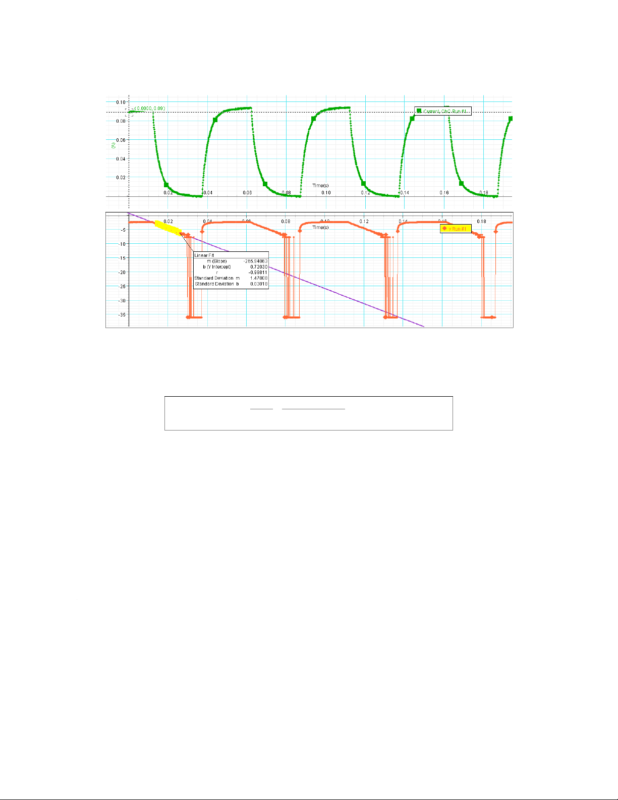
b. With coreVS = 1.00 (V)I0 = 0.09 (A)Slope So= 265.94063Coil inductance :Explain: After putting the core inside the coil, the coil’s inductance is significantly increase (from 0.008 H to 0.042 H) . Tài liệu giúp bạn tham khảo, ôn tập và đạt kết quả cao. Mời đọc đón xem!
Môn: Vật lý đại cương 2 298 tài liệu
Trường: Học viện Công Nghệ Bưu Chính Viễn Thông 1.7 K tài liệu
Tác giả:


Preview text:
Experimental Report 3
INDUCTOR AND FREE OSCILLATION IN RLC CIRCUIT Full Name: Pham Mai Anh Student ID: 20210053
Class: CTTT Cơ điện tử 03 - K66 Group: 1
Verification of the instructors
I. Experiment Motivations
- Understanding the current across an inductor-resistor and RLC circuit.
- Calculating the energy of the oscillation RLC circuit. II. Experimental result
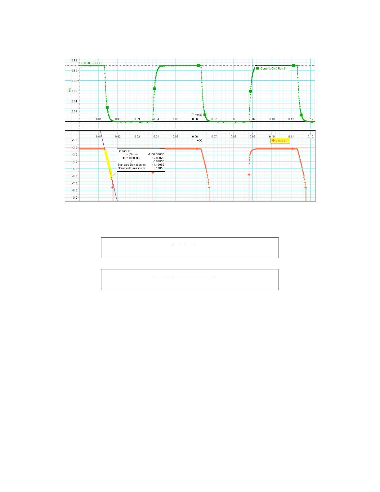
1. Resistance and Inductance of the coil a. Without core VS = 1.00 (V) I0 = 0.11 (A) Slope Sw/o = 1139.51036
The resistance of the coil: RL=VS =1.00 0.11=9.09(Ω) IO Coil inductance : LW/O=VS IO×S=1.00
0.11×1139.51036=0.008(H) b. With core VS = 1.00 (V) I0 = 0.09 (A) Slope So= 265.94063 Coil inductance : LWO=VS IO×S =1.00
0.09×265.94063=0.042(H)
Explain: After putting the core inside the coil, the coil’s inductance is significantly increase (from
0.008 H to 0.042 H). This phenomenon occurred because the core has higher permeability than the air,
so magnetic field can be transferred through the core easier, thus the coil inductance increase.
2. Free oscillation of the RLC circuit a. Frequency
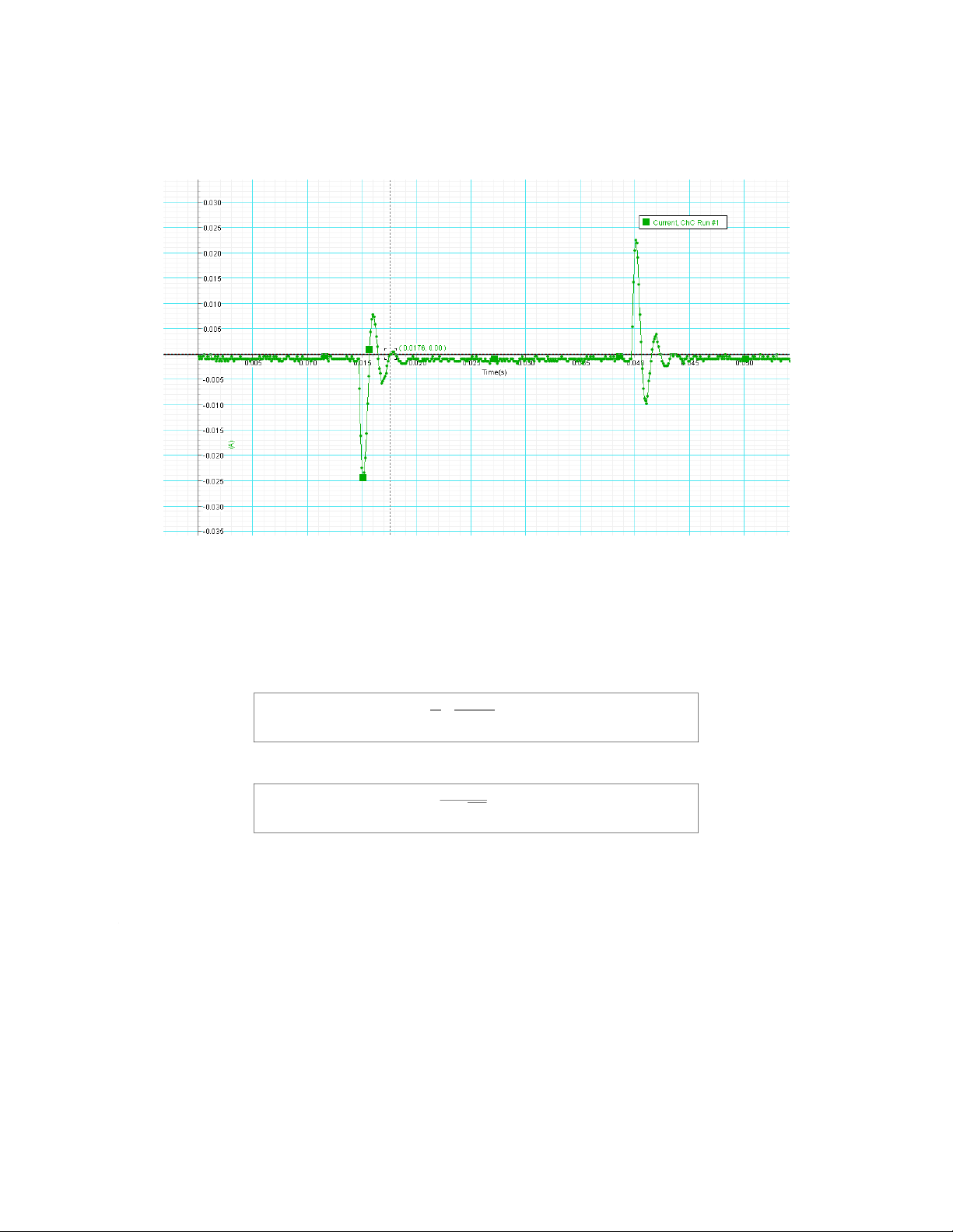
The current in RLC circuit: T = t - t 2 1 t1 = 0.0157 (s) t2 = 0.0176 (s) T = 0.0019 (s) Lw/o = 0.008 (H) C = 10 x 10-6 (F)
The frequency based on the graph:
fmeasured=1T=10.0019=526.32(Hz)
The frequency based on theoretical calculation: fprediction=1 LC=562.70(Hz) 2π √ Comparison:
Δf=fprediction−fmeasured=562.70 526.32 36.38 − = (Hz) b. Energy
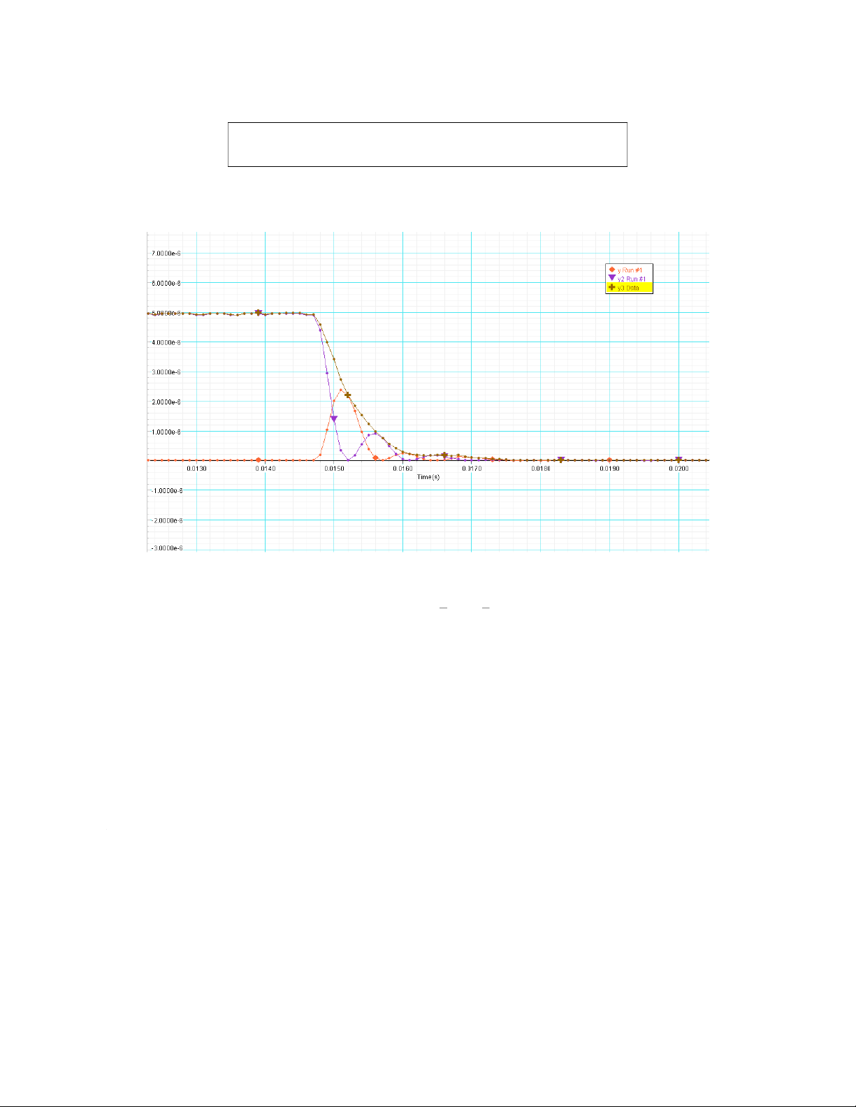
The total energy in RLC circuit:
U=Uc+UL=1 2CV2+1 2Li2 Comment:
- After stopping the electric power, the energy of the circuit does not decrease rapidly to zero, it
reduces to zero over a short period of time.
- The energy of oscillations of the coil and the capacitor are damped oscillations. Explain:
The energy of the circuit loses by the heat of the resistor at rate i2R
The graph of total energy is steepest at the time that the magnetic energy reaches a local maximum
because in these times, the current through the coil is highest, and the loss of energy is mainly due to
the resistance of the coil (ΔQ=i2R ).
Tài liệu liên quan:
-
Bài tập Vật lý nguyên tử môn Vật lý đại cương 2 | Học viện Công Nghệ Bưu Chính Viễn Thông
11 6 -
Bài tập Vật lý nguyên tử môn Vật lý đại cương 2 | Học viện Công Nghệ Bưu Chính Viễn Thông
12 6 -

Tán xạ ánh sáng và Hiệu ứng Tyndall - Lý thuyết và Ứng dụng môn Vật lý đại cương 2 | Học viện Công Nghệ Bưu Chính Viễn Thông
20 10 -

Chương 23: Quang học lượng tử môn Vật lý đại cương 2 | Học viện Công Nghệ Bưu Chính Viễn Thông
18 9 -

Chương 24: Cơ Học Lượng Tử - Tính Sóng-Hạt và Phương Trình Schrödinger môn Vật lý đại cương 2 | Học viện Công Nghệ Bưu Chính Viễn Thông
19 10