Experimental report 3 Inductor and free oscillation in rlc circuit môn Vật lý đại cương 2 | Học viện Công Nghệ Bưu Chính Viễn Thông
Experimental report 3 Inductor and free oscillation in rlc circuit mônVật lý đại cương 2 | Học viện Công Nghệ Bưu Chính Viễn Thông. Tài liệu giúp bạn tham khảo, ôn tập và đạt kết quả cao. Mời đọc đón xem!
Môn: Vật lý đại cương 2 298 tài liệu
Trường: Học viện Công Nghệ Bưu Chính Viễn Thông 1.7 K tài liệu
Tác giả:


Preview text:
Experimental Report 3
INDUCTOR AND FREE OSCILLATION IN RLC CIRCUIT Class: 746167
Verification of the instructors Group: 3 Name: Bùi Quang Huy Student ID: 20233961 I. Experiment Motivations
-Understanding the current across an inductor-resistor and RLC circuit.
-Calculating the energy of the oscillation RLC circuit. II. Experimental result
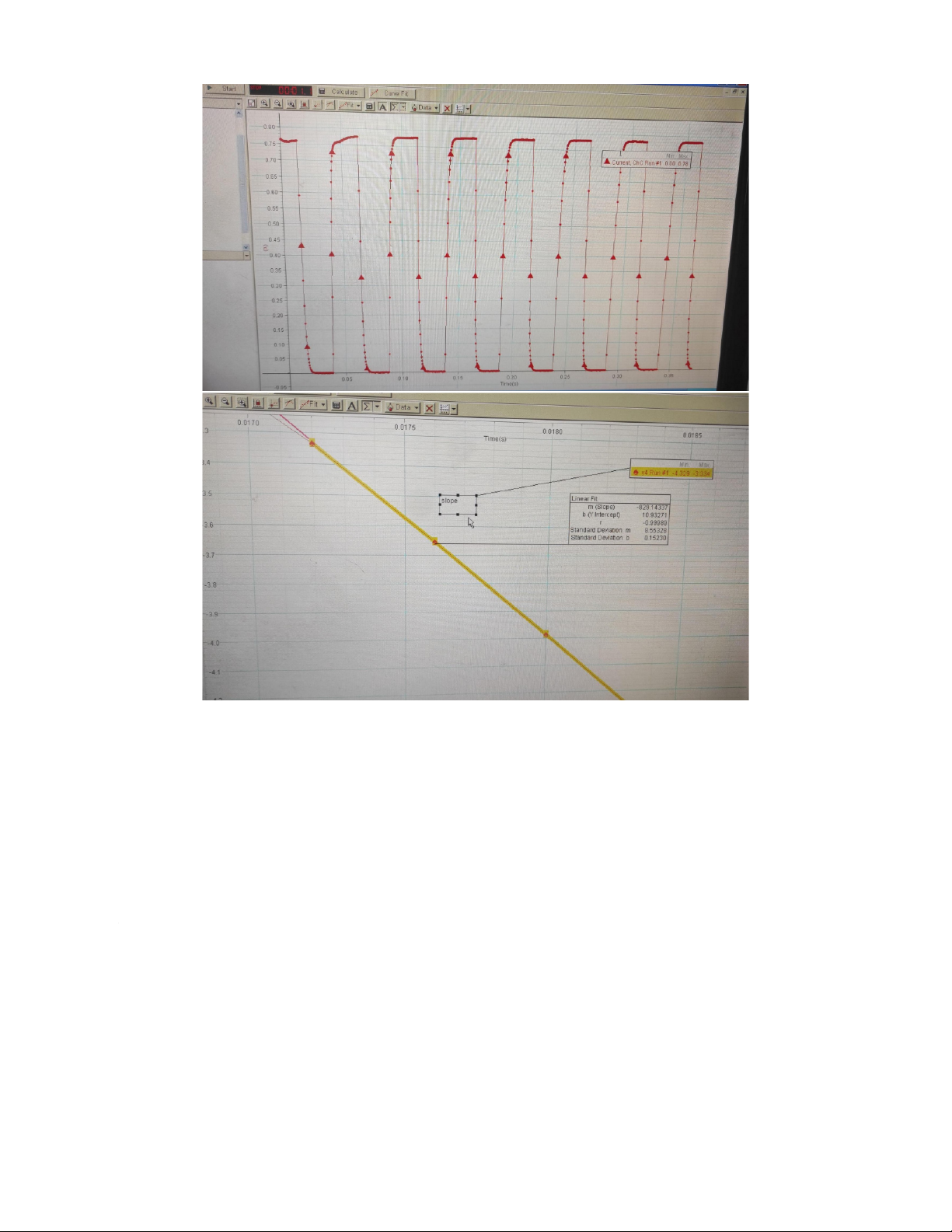
Part 1: Resistance and Inductance of the coil VS = 5.00 (V) I0 = 0.78 (A) Slope S = 829
The resistance of the coil: RL=VS =5.00 0.78=6.41(Ω) IO Coil inductance: LW/O=VS IO×S=5.00
0.78×829=7.73×10⁻³(H)
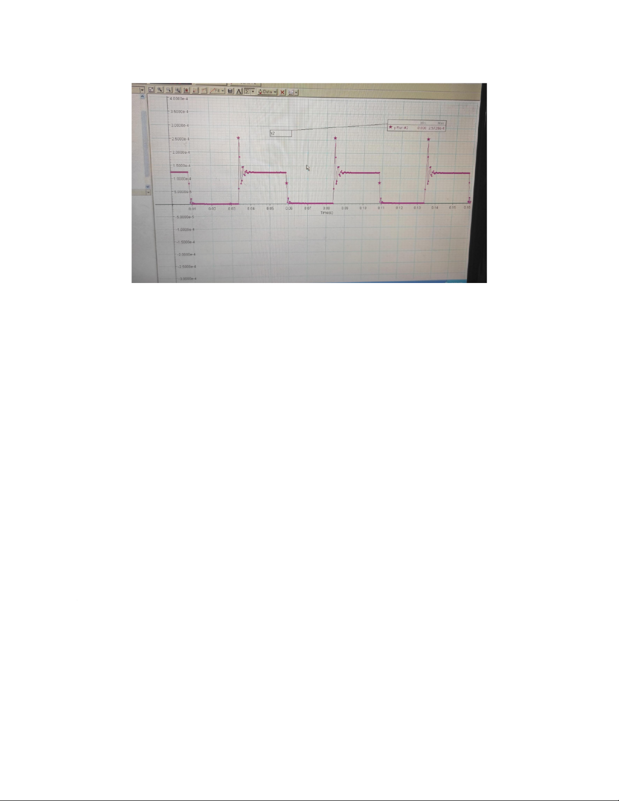
Part 2: Free oscillation of the RLC circuit a. Frequency
The current in RLC circuit: T = 0.0017 (s) Lw/o = 8.2 x 10⁻³ (H) C = 10 x 10-6 (F)
The frequency based on the graph:
fmeasured=1T=10.0017=588.2(Hz)
The frequency based on theoretical calculation: fprediction=1 LC=1 8.2 10 ×
−3×10×10−6=555.8(Hz) 2π √ 2π √ Comparison:
Δf=fmeasured−fprediction=588.2 555.8 − =32.4(Hz) b. Energy
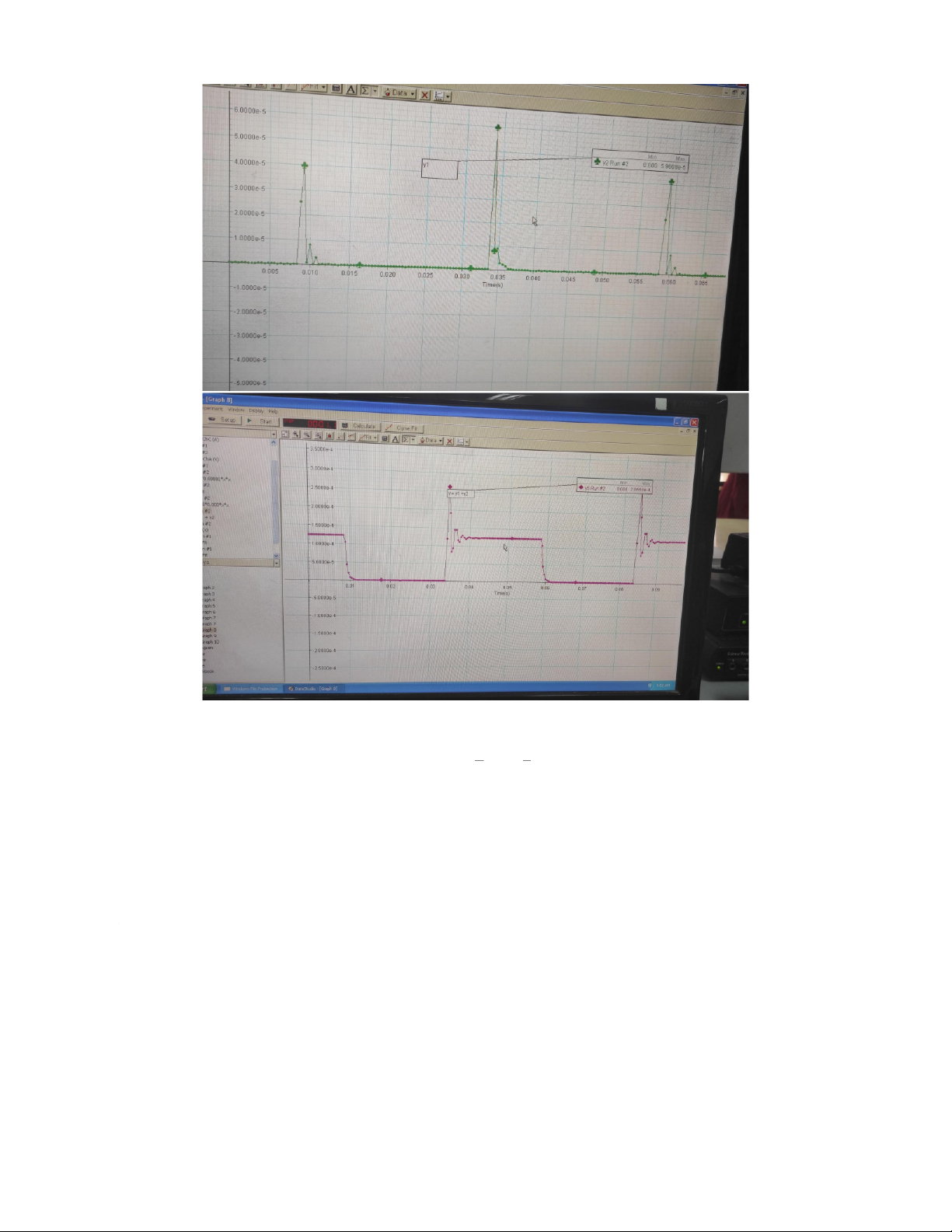
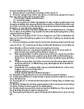
The total energy in RLC circuit:
U=Uc+UL=1 2CV2+1 2LI2 Comment:
- After stopping the electric power, the energy of the circuit does not decrease
rapidly to zero, it reduces to zero over a short period of time.
- The energy of oscillations of the coil and the capacitor are damped oscillations. Explain:
The energy of the circuit loses by the heat of the resistor at rate i2R
The graph of total energy is steepest at the time that the magnetic energy reaches a
local maximum because in these times, the current through the coil is highest, and
the loss of energy is mainly due to the resistance of the coil (ΔQ=i2R ).
Tài liệu liên quan:
-
Bài tập Vật lý nguyên tử môn Vật lý đại cương 2 | Học viện Công Nghệ Bưu Chính Viễn Thông
11 6 -
Bài tập Vật lý nguyên tử môn Vật lý đại cương 2 | Học viện Công Nghệ Bưu Chính Viễn Thông
11 6 -

Tán xạ ánh sáng và Hiệu ứng Tyndall - Lý thuyết và Ứng dụng môn Vật lý đại cương 2 | Học viện Công Nghệ Bưu Chính Viễn Thông
19 10 -

Chương 23: Quang học lượng tử môn Vật lý đại cương 2 | Học viện Công Nghệ Bưu Chính Viễn Thông
17 9 -

Chương 24: Cơ Học Lượng Tử - Tính Sóng-Hạt và Phương Trình Schrödinger môn Vật lý đại cương 2 | Học viện Công Nghệ Bưu Chính Viễn Thông
18 9