Experimental Report 4: Verification of Electromagnetic Induction Law môn Vật lý đại cương 2 | Học viện Công Nghệ Bưu Chính Viễn Thông
A voltage is induced in a circuit whenever relative motion existsbetween a conductor and a magnetic field and that the magnitude of this voltage is proportional to the rate of change of the flu . Tài liệu giúp bạn tham khảo, ôn tập và đạt kết quả cao. Mời đọc đón xem!
Môn: Vật lý đại cương 2 298 tài liệu
Trường: Học viện Công Nghệ Bưu Chính Viễn Thông 1.7 K tài liệu
Tác giả:


Preview text:
Experimental Report 4
VERIFICATION OF FARADAY’S LAW OF ELECTROMAGNETIC INDUCTION
Verification of the instructors Class: ME-E1 02 Group: 4
Name: Hoàng Phi Long
Student ID: 20185272
I/Experiment Motivations
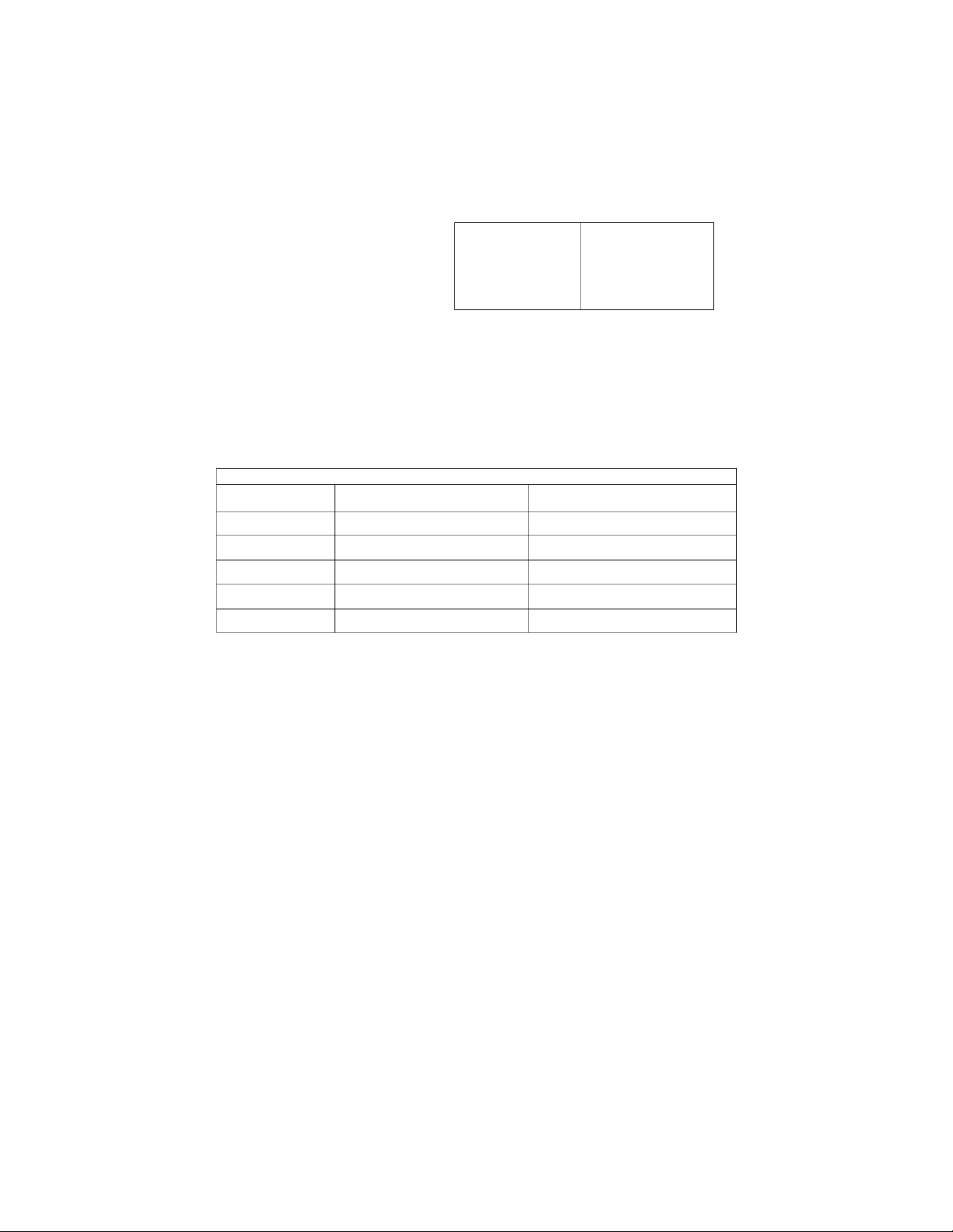
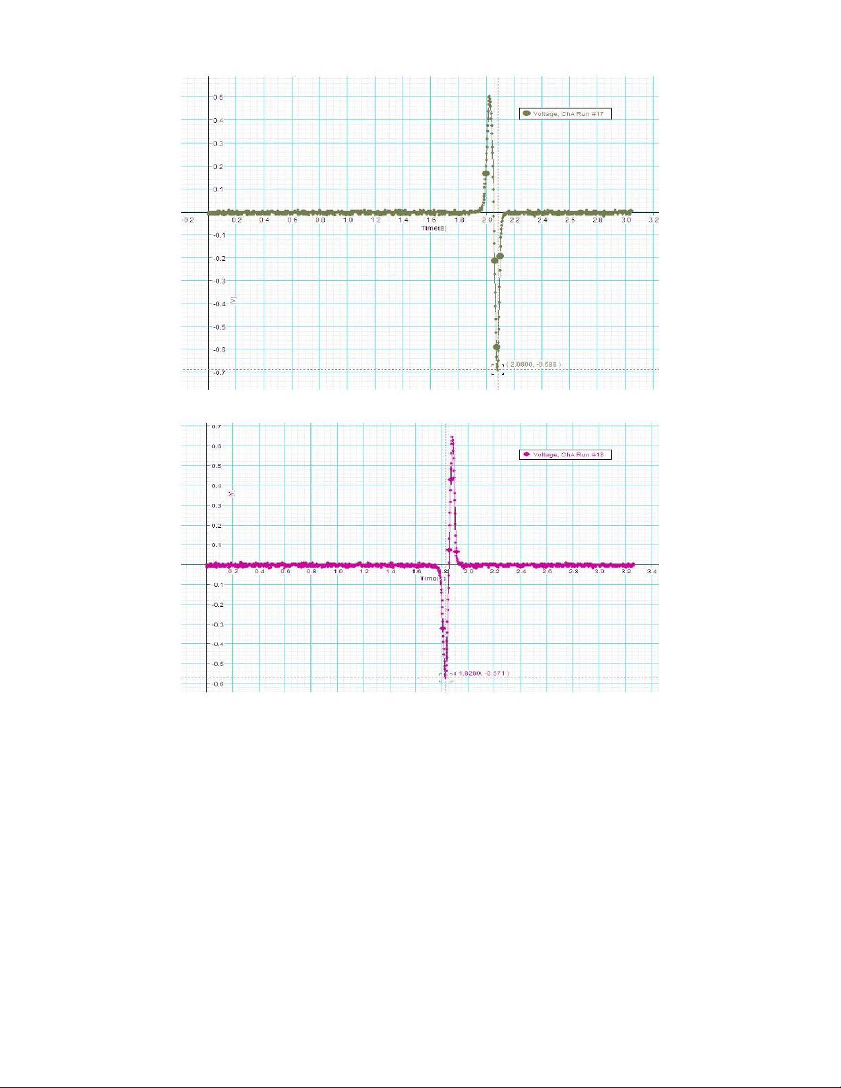
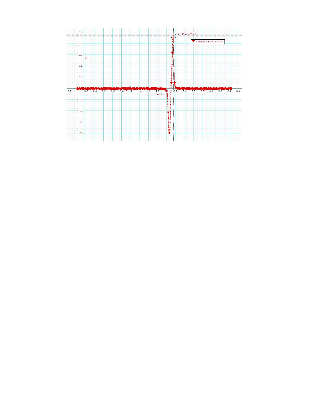
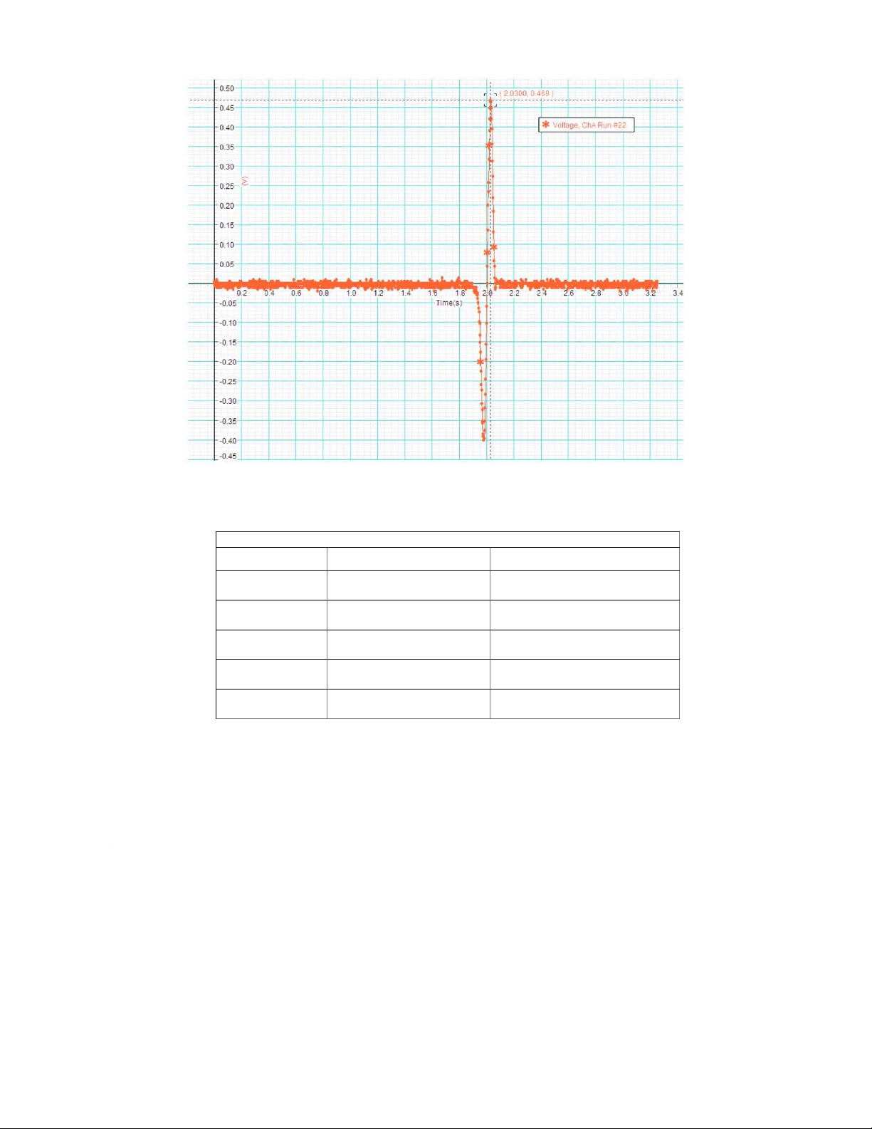
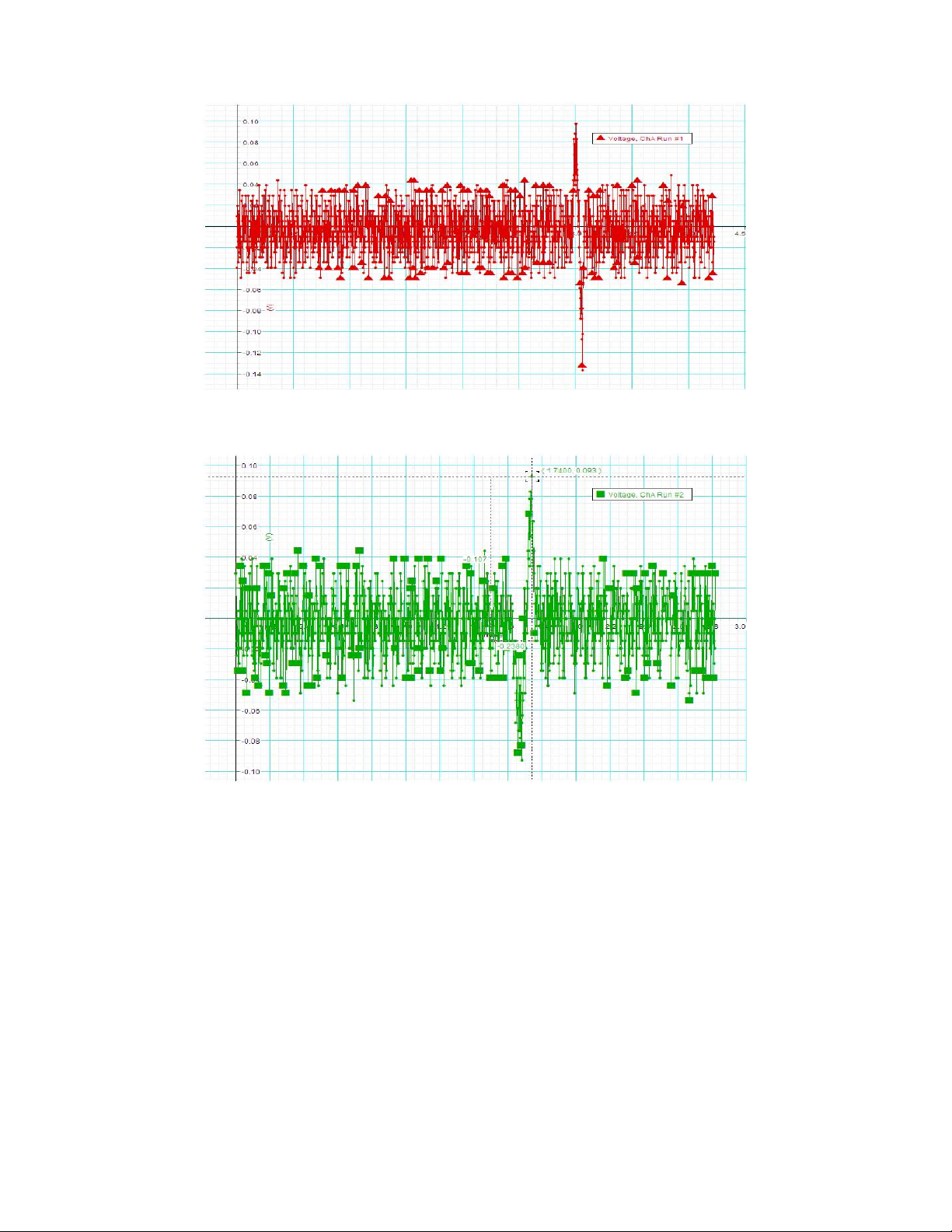
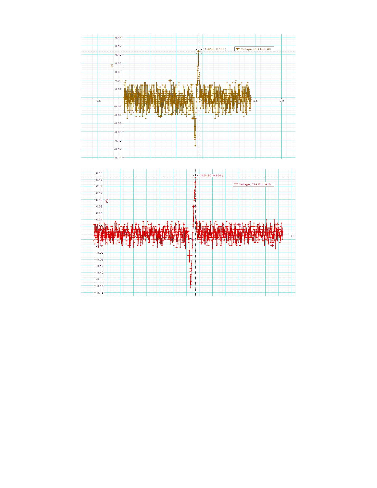
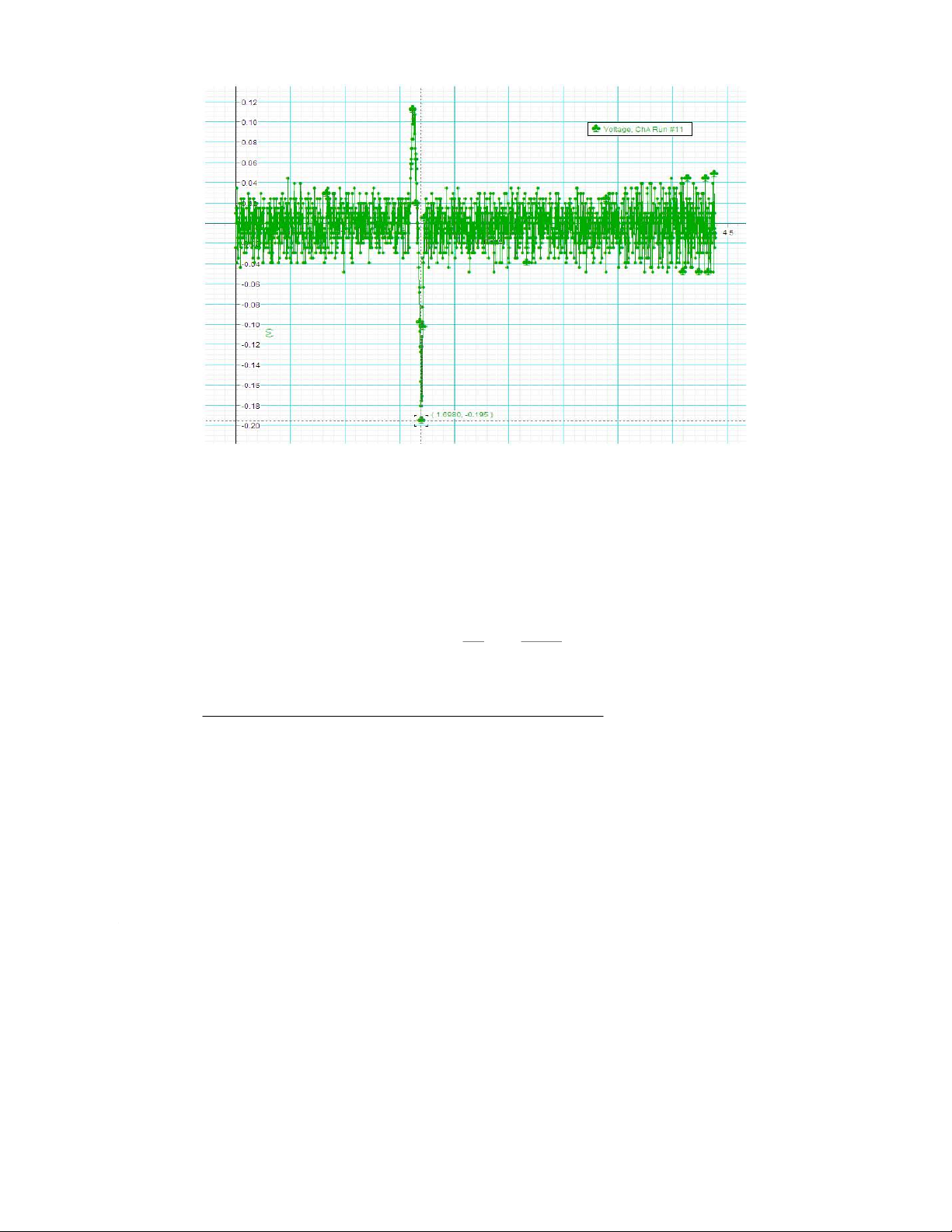
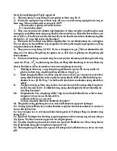
- Verify Faraday’s law of electromagnetic induction II/Experimental result 1)1200 turn coil R = 12 (Ω); L = 12 (mH) Pole Voltage Peak 1 Voltage Peak 2 North 0.503 -0.688 South -0.571 0.645 North-South -0.405 0.469 North-North 0.347 -0.488 South-South -0.400 0.469 Graph North South North-South South-South 2)150 turn coil R = 0.4 (Ω); L = 1 (mH) Pole Voltage Peak 1 Voltage Peak 2 North 0.098 -0.137 South -0.093 0.093 North-South -0.112 0.107 North-North -0.166 0.166 South-South 0.122 -0.195 Graph North South North-South North-North South-South
III/Comment and Explanation
Faraday’s Law of Electromagnetic Induction:
A voltage is induced in a circuit whenever relative motion exists between a conductor and a
magnetic field and that the magnitude of this voltage is proportional to the rate of change of the flux
Vinduced=−NΔΦΔt =−NΔ(BA) Δt So, we have:
+) Comparison between the first voltage peak and second voltage peak:
-The two voltage peak has opposite sign corresponding to the direction of the magnetic field
line’s rate and direction of change. According to Faraday’s Law, the induced electromotive
force acts in the direction that opposes the change in magnetic flux.
-Also, the magnitude of second voltage peak is greater than that of the first peak.This can be
explained by the motion of the magnet bar. When the magnet is released to fall through the
coil, its motion is free fall. Therefore, the velocity of the bottom pole when it falls through
the coil is larger than that of the top pole. This means the change in magnetic field increases
in time, and according to the Faraday’s Law above, this result in the greater magnitude of the second peak. +) The shape of the graph
-Both graphs are approximately symmetric about the point when Δ ΦB=0 (rate of change
of the magnetic field flux equals zero). This can be explained by Faraday’s law, which
states that the induced voltage through the wire induces a current that creates a magnetic
flux in the direction opposing the change in flux, and the fact that the magnetic field line
going in/out the north and the south pole of the magnet are exactly the same. +) Comparison between two coil
-The maximum voltage for the coil with more turns is higher than the one with fewer turn,
because the magnitude of voltage is proportional to the number of turns in the coil, as shown in the equation: Vinduced=−NΔΦΔt
Tài liệu liên quan:
-
Bài tập Vật lý nguyên tử môn Vật lý đại cương 2 | Học viện Công Nghệ Bưu Chính Viễn Thông
11 6 -
Bài tập Vật lý nguyên tử môn Vật lý đại cương 2 | Học viện Công Nghệ Bưu Chính Viễn Thông
12 6 -

Tán xạ ánh sáng và Hiệu ứng Tyndall - Lý thuyết và Ứng dụng môn Vật lý đại cương 2 | Học viện Công Nghệ Bưu Chính Viễn Thông
20 10 -

Chương 23: Quang học lượng tử môn Vật lý đại cương 2 | Học viện Công Nghệ Bưu Chính Viễn Thông
18 9 -

Chương 24: Cơ Học Lượng Tử - Tính Sóng-Hạt và Phương Trình Schrödinger môn Vật lý đại cương 2 | Học viện Công Nghệ Bưu Chính Viễn Thông
19 10