Experimental report 5 Investigation of transmission of Electromagnetic wave (microwave) môn Vật lý đại cương 2 | Học viện Công Nghệ Bưu Chính Viễn Thông
The maximum voltage is obtained when the transmitter and the receiver oppose each other along a straight line . Tài liệu giúp bạn tham khảo, ôn tập và đạt kết quả cao. Mời đọc đón xem!
Môn: Vật lý đại cương 2 298 tài liệu
Trường: Học viện Công Nghệ Bưu Chính Viễn Thông 1.7 K tài liệu
Tác giả:

Preview text:
Experimental Report 5
INVESTIGATION OF TRANSMISSION OF ELECTROMAGNETIC WAVE (MICROWAVE)
Verification of the instructors Name: Bùi Hoàng Quang Huy Student ID: 202414727 Class: 760048 Group: 5
I. Purpose of experiment
- To evaluate both qualitative and quantitative results of transmitting and receiving microwave. II. LAB Report
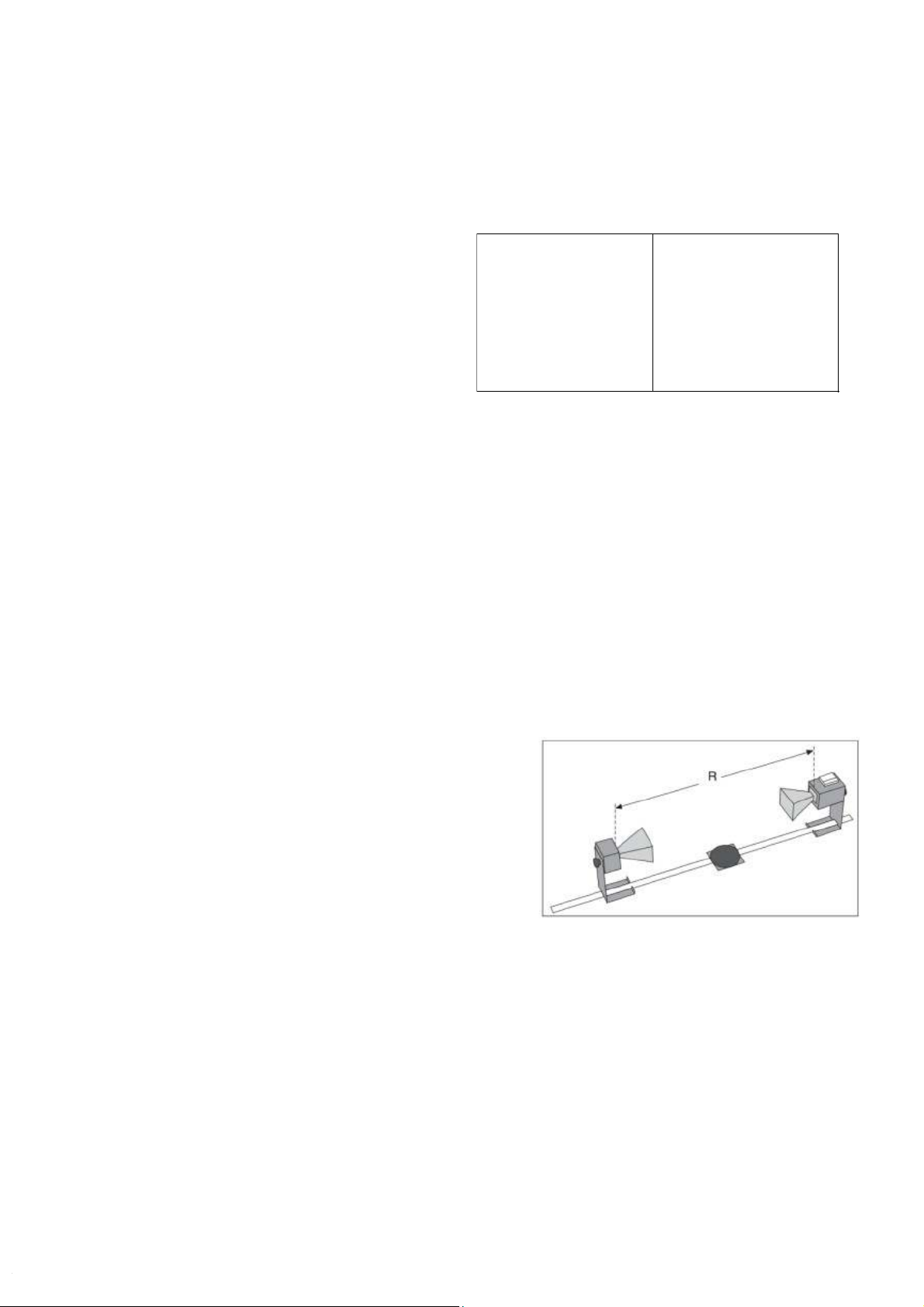
1. Investigation of straight-line propagation of microwaves Observation:
- The maximum voltage is obtained when
the transmitter and the receiver oppose
each other along a straight line.
- When the receiver is moved away from
the optimum position, the value of volt- meter decreases. Conclusion:
- Microwave propagates greatest in straight line.
2. Investigation of penetration of microwaves Observation:
- When the microwaves pass through a dry absorption plate which is put
between the transmitter and the receiver, the voltmeter’s value slightly decreases. Conclusion:
- Microwaves can penetrate through the dry absorption plate.
- However, some small parts of them are absorbed by the absorption plate.
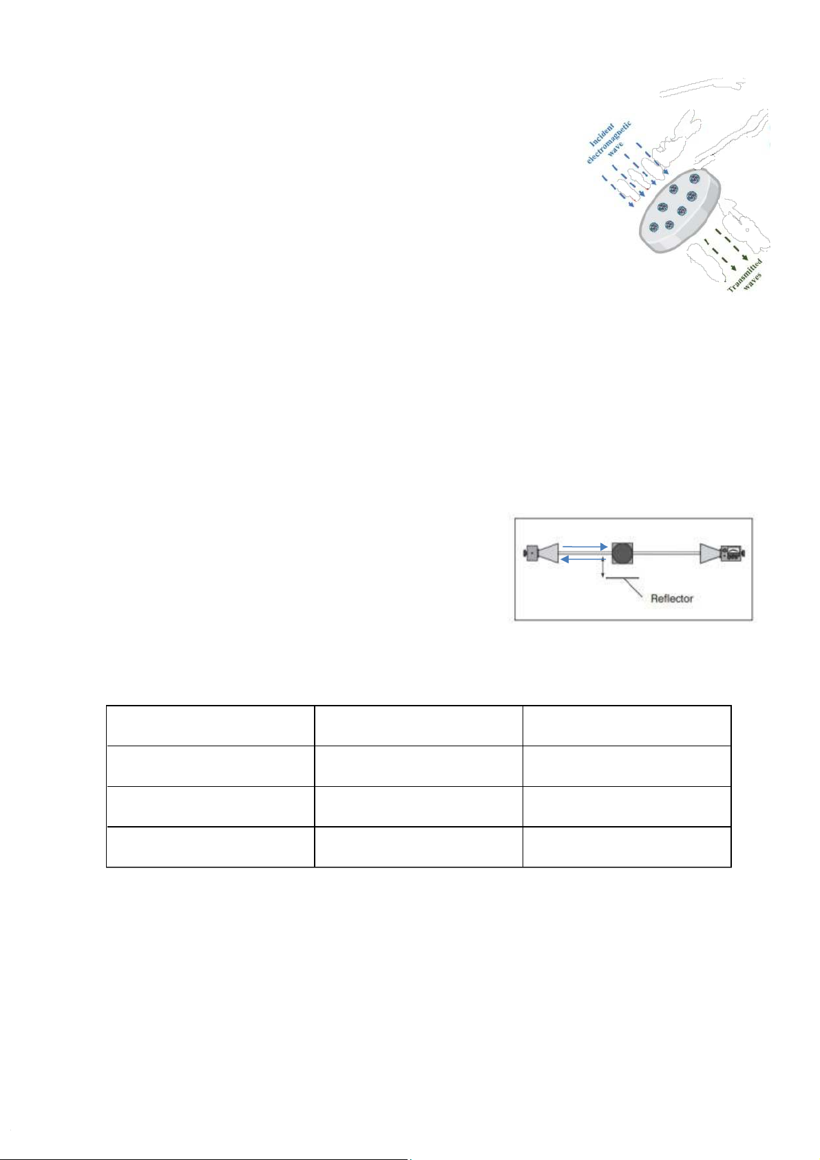
3. Investigation of screening and absorption of microwaves Observation:
-When a reflection plate (electrical conductor) is put between the transmitter
and the receiver, the voltmeter shows a value that is approximately zero.
This value is extremely small compared to the case of placing absorption plate as above. Conclusion:
- Most microwaves will not pass through the
reflection plate as being reflected.
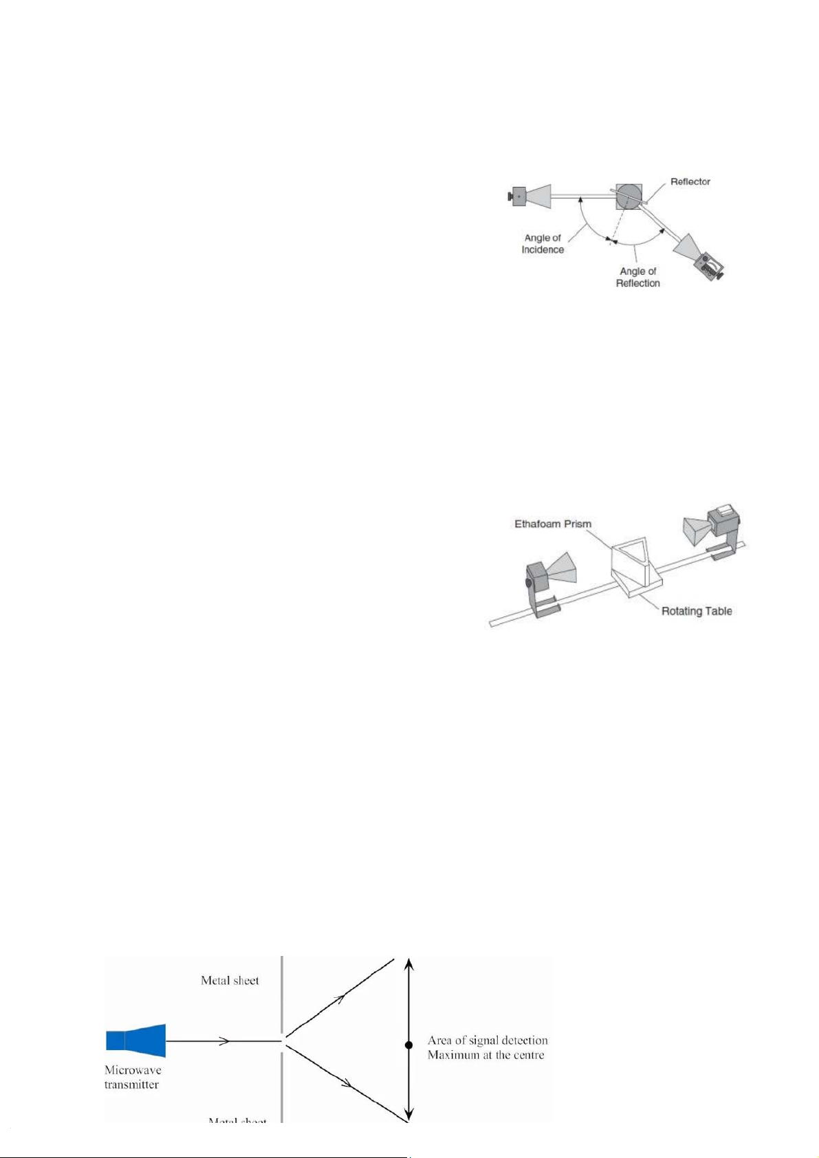
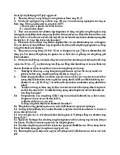
4. Investigation of reflection of microwaves Observation: Angle (o) Incident Angle (o) Voltage value 30 30 1.485 40 30 1.425 50 30 1.377
- Maximum value is recorded when the reflector angle and incident angle
are the same. The voltmeter’s value decreases as incident angle moves
away from the optimum position. Conclusion:
- Microwave reflects greatest when perpendicular bisector of the reflection
plate is the bisector of an angle created by the transmitter and the receiver.
- When the microwave reflects, the angle of
incidence equals the angle of reflection.
5. Investigation of refraction of microwaves Observation:
- When the angle formed by 2 rails is 140o, the voltmeter shows the maximum value.
- As we move one rail away from the initial angle, the value of voltmeter decreases. Conclusion:
- Microwave refracts greatest with angle of 140o
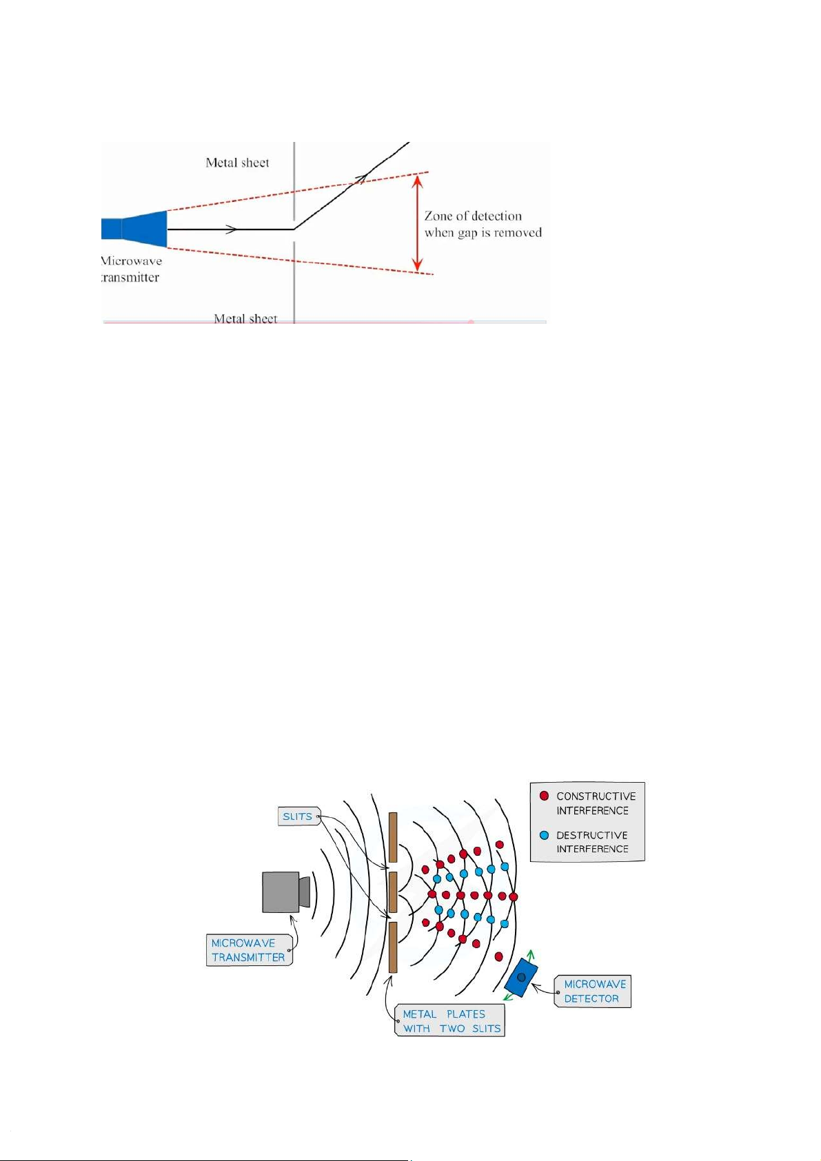
6. Investigation of diffraction of microwaves Observation:
- When the plate is placed between the probe and the transmitter, the value on
the voltmeter is approximately zero in region around the center. If the probe
is moved on the horizontal plane (parallel to the plate), the voltage increases.
- When the single slit is put in the rail between the transmitter and the
receiver, the voltage is approximately zero as the angle of receiver
corresponding to the rail is 40 o. Maximum value is recorded at region around the center. Conclusion:
- Microwaves have diffraction properties.
7. Investigation of interference of microwaves Observation:
- When the probe is moved parallel to the plate, the value on the voltmeter
is fluctuating. At the straight line through the center of the double slit, the
value is maximum. As we move the probe away, the value decreases,
however at some particular points, the voltage increases. There are three
maximas that have been detected. Conclusion:
- Microwaves have property of interference.
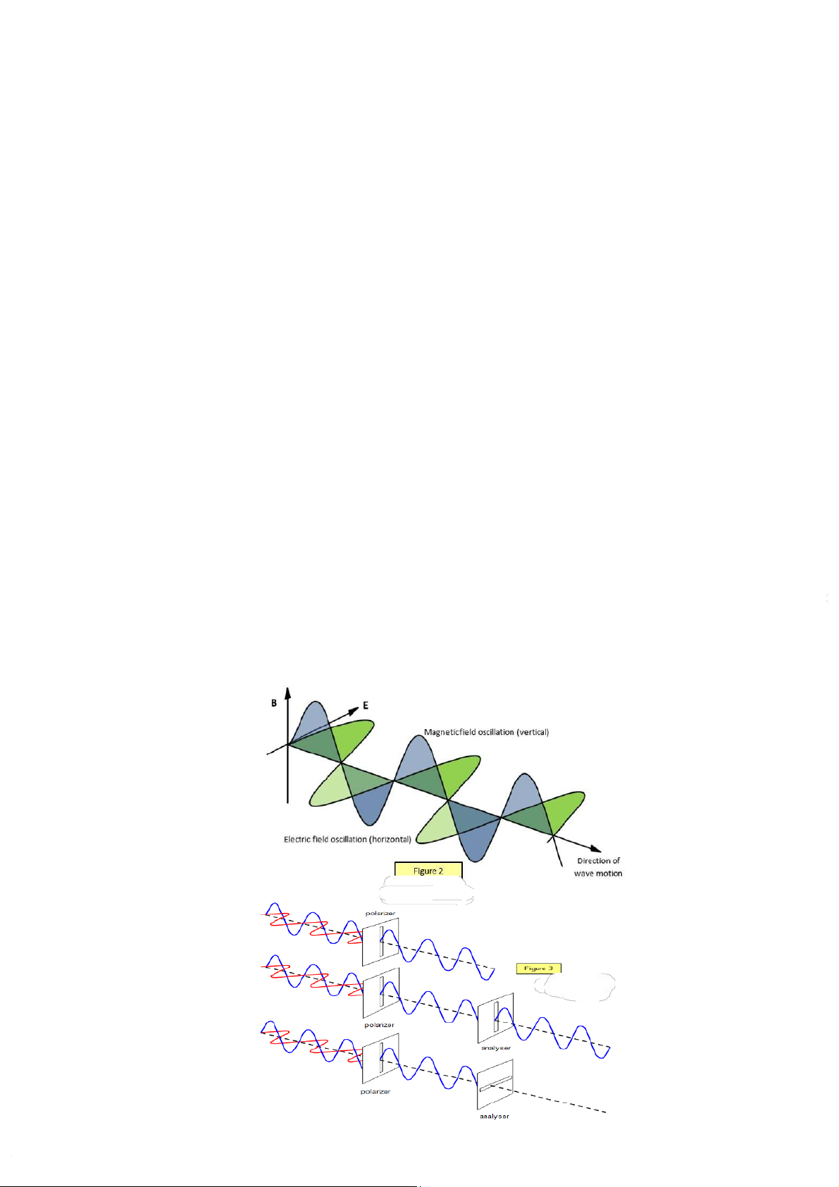
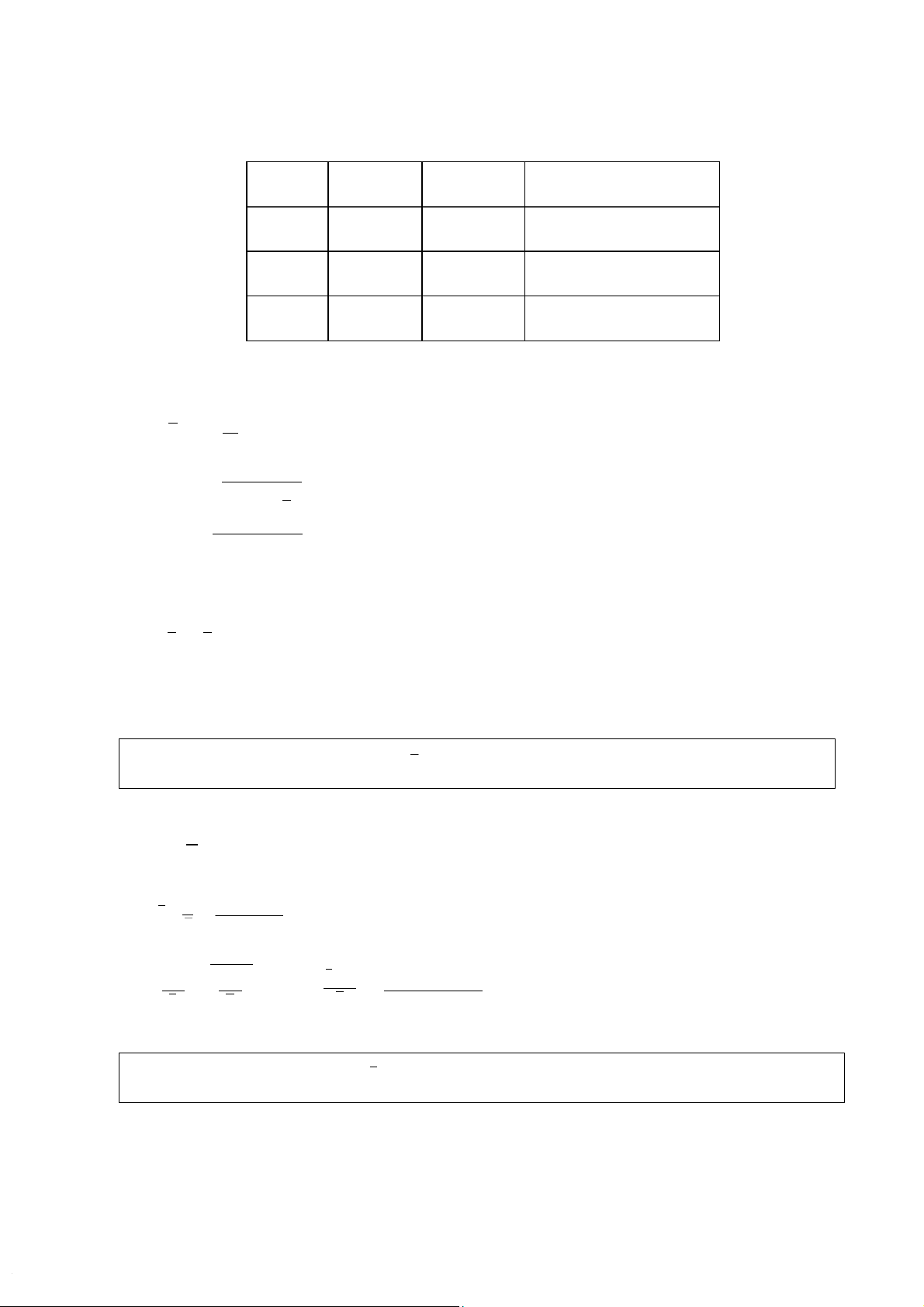
8. Investigation of polarization of microwaves Observation:
- When the polarization grating is aligned horizontally, the value of the voltmeter slightly decreases.
- When the polarization grating is aligned vertically, the value of the
voltmeter is approximately zero.
- When the polarization grating is aligned at 45 o, the value of the voltmeter decreases nearly by half. T
he receiver’s signal is smaller than when we use
vertical polarization grating and bigger than when we use horizontal polarization grating. Conclusion:
- The polarization grating acts like a filter that selectively transmits
microwaves based on their polarization. The orientation of the grating defines
which polarization is allowed to pass through effectively. The results illustrate
fundamental principles of electromagnetic waves, showing how their
polarization can be manipulated and measured.
9. Determining wavelength of standing waves Trials x1 (mm) x2 (mm) d (mm) = x2 – x1 1 77 95 18 2 75 94 19 3 78 95 17 The mean value of d: 3di d =∑ = 18 (mm) i=1 3 The uncertainty of d: √3∑ (di−d )2 = 0.50 (mm) Δd= i=1 3
From the wavelength’s equation: λ=2d
The mean value and the uncertainty of wavelength: λ=2d = 36 (mm) And Δλ=2Δd = 1 (mm) Therefore λ± Δλ=36±1 (mm)
The frequency of the microwaves: f=c λ
The mean value and the uncertainty of the microwaves: f=c 3×10⁸ λ =36×10 =8.33×10⁹ (Hz) −3 And Δf Δf=fΔλ 8.33×109×1 f= √(Δλ)2=> = 0.20 λ λ = 36 ×109 (Hz) Therefore
f ±Δf=¿ 8.3± 0.2) ×109 (Hz)
Tài liệu liên quan:
-
Bài tập Vật lý nguyên tử môn Vật lý đại cương 2 | Học viện Công Nghệ Bưu Chính Viễn Thông
11 6 -
Bài tập Vật lý nguyên tử môn Vật lý đại cương 2 | Học viện Công Nghệ Bưu Chính Viễn Thông
11 6 -

Tán xạ ánh sáng và Hiệu ứng Tyndall - Lý thuyết và Ứng dụng môn Vật lý đại cương 2 | Học viện Công Nghệ Bưu Chính Viễn Thông
19 10 -

Chương 23: Quang học lượng tử môn Vật lý đại cương 2 | Học viện Công Nghệ Bưu Chính Viễn Thông
17 9 -

Chương 24: Cơ Học Lượng Tử - Tính Sóng-Hạt và Phương Trình Schrödinger môn Vật lý đại cương 2 | Học viện Công Nghệ Bưu Chính Viễn Thông
18 9