Giáo trình môn Thông tin di động | Đại học Bách Khoa Hà Nội
Tài liệu gồm 199 trang, có 4 chương chính bao gồm các kiến thức cơ bản liên quan: lịch sử phát triển của hệ thống truyền thông di động; hệ thống GSM;... giúp bạn ôn luyện và nắm vững kiến thức môn học đại cương Thông tin di động. Mời bạn đọc đón xem!
Môn: Thông tin di động 21 tài liệu
Trường: Đại học Bách Khoa Hà Nội 5.8 K tài liệu
Tác giả:


Preview text:
2/17/2014
Trường Đại học Bách Khoa Hà Nội
Khoa Điện tử Viễn thông Thông tin di động Mobile Communications
TS. Đỗ Trọng Tuấn
Bộ môn Kỹ thuật thông tin Hà Nội, 8-2010 1 2/17/2014 Nội dung
• Tổng quan về thông tin di động số tế bào.
• Hệ thống TTDĐ 2G (GSM,GPRS)
• Hệ thống TTDĐ 3G (UMTS,HSDPA)
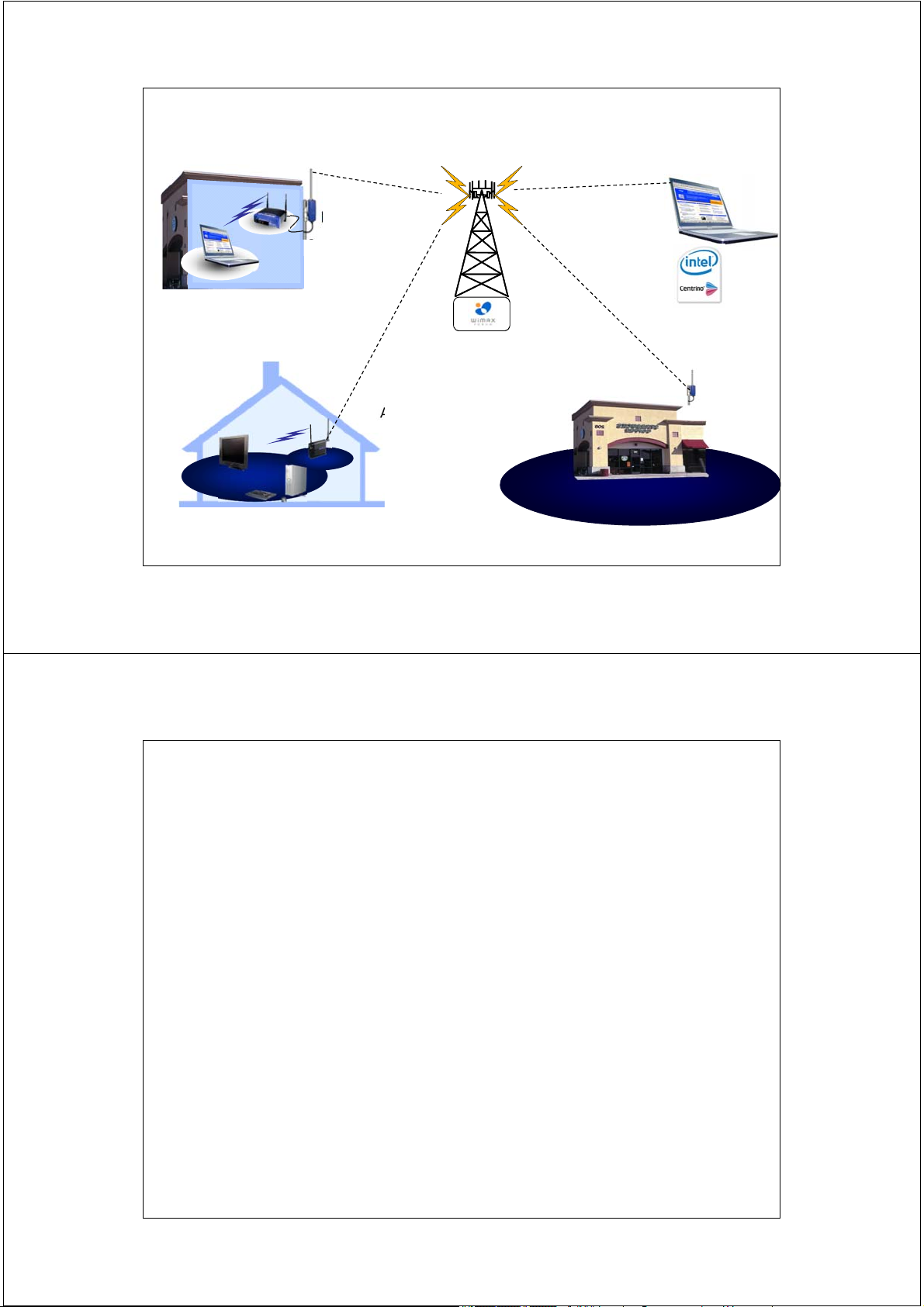
• Mạng không dây WiFi – WiMax
• Quy hoạch và định cỡ mạng 3G/UMTS 2 2/17/2014 Tài liệu tham khảo
• Giáo trình thông tin di động, ĐHBK Hà Nội
• Lý thuyết về kênh vô tuyến – Thầy Nguyễn Văn Đức
• Tính toán mạng thông tin di động số cellular - Thầy Vũ Đức Thọ
• Principles of Mobile Communication, Gordon L. Stüber
• Wireless Communications Principles and Practice, T Rappaport
• Understanding UMTS Radio Network Modelling, Planning
and Automated Optimisation, Maciej J. Nawrocki, Mischa Dohler, A. Hamid Aghvami • http://www.google.com 3 2/17/2014 CHƯƠNG 1
Tổng quan về thông tin di động số tế bào
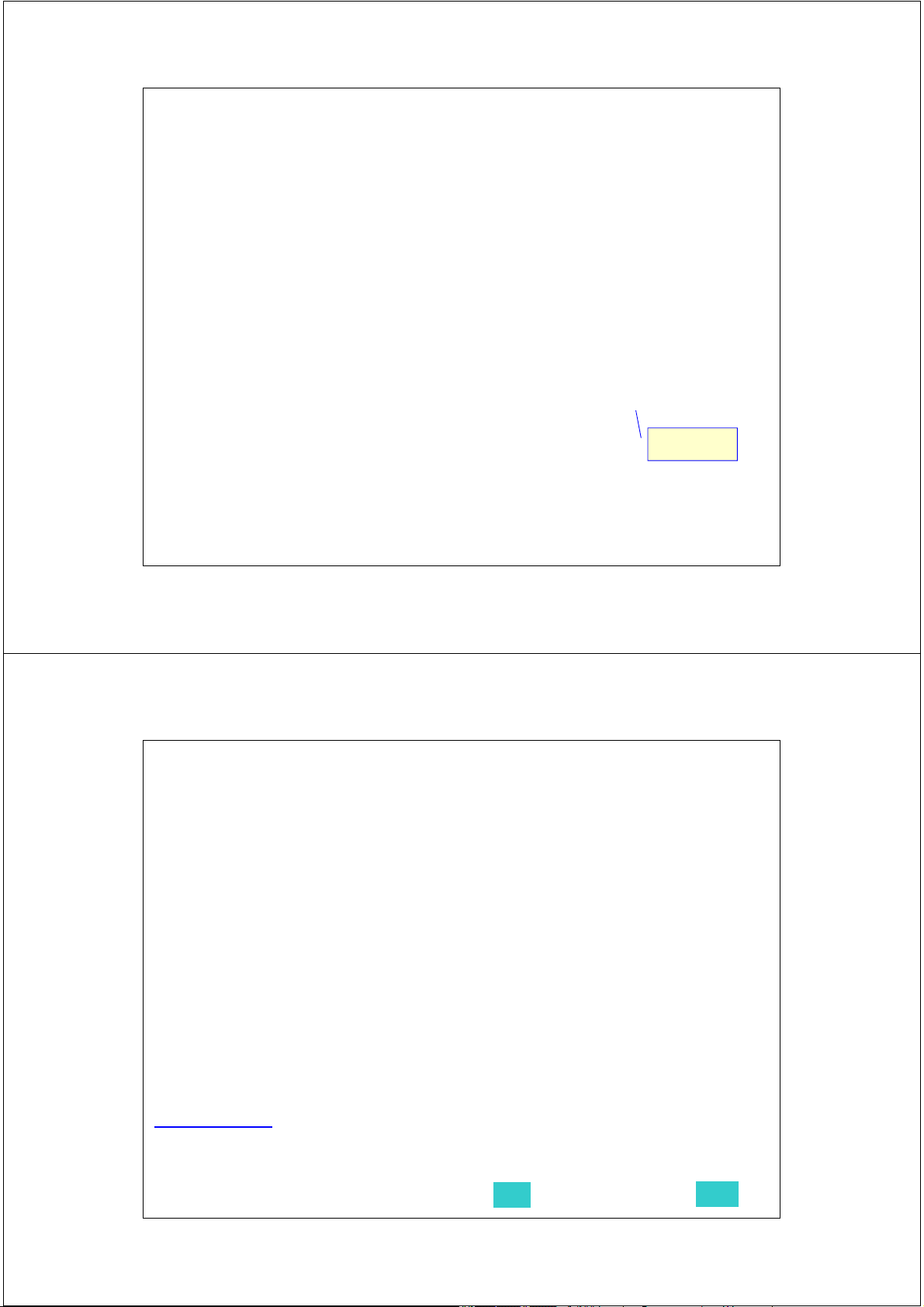
(Cellular Mobile Communications) 4 2/17/2014 Introduction Cellular mobile communication
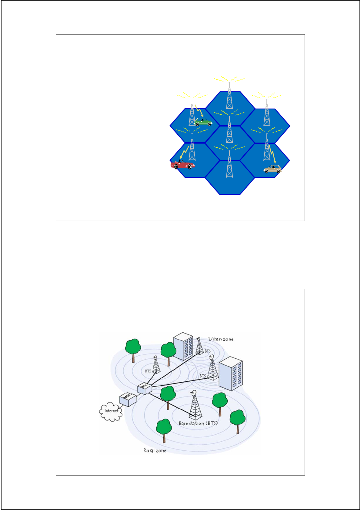
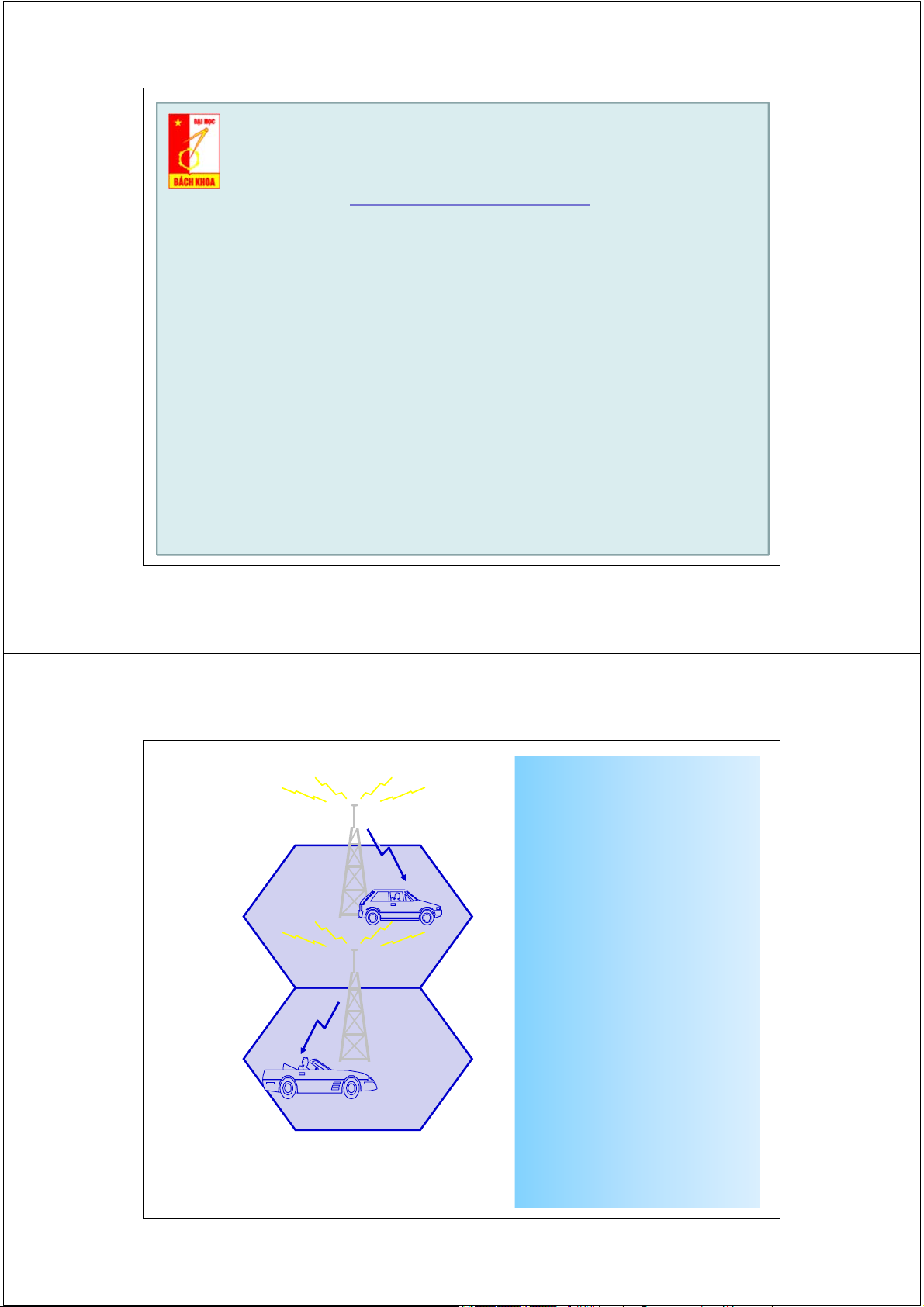
systems, or just mobile systems are communication systems with many access points, or base stations. Each base station
supports its nearby geographical
area, called a cell. The user can move around with his mobile phone and communicate through the nearest base station 5 5 2/17/2014 Cellular Mobile Systems 6 6 2/17/2014 Cellular Concept
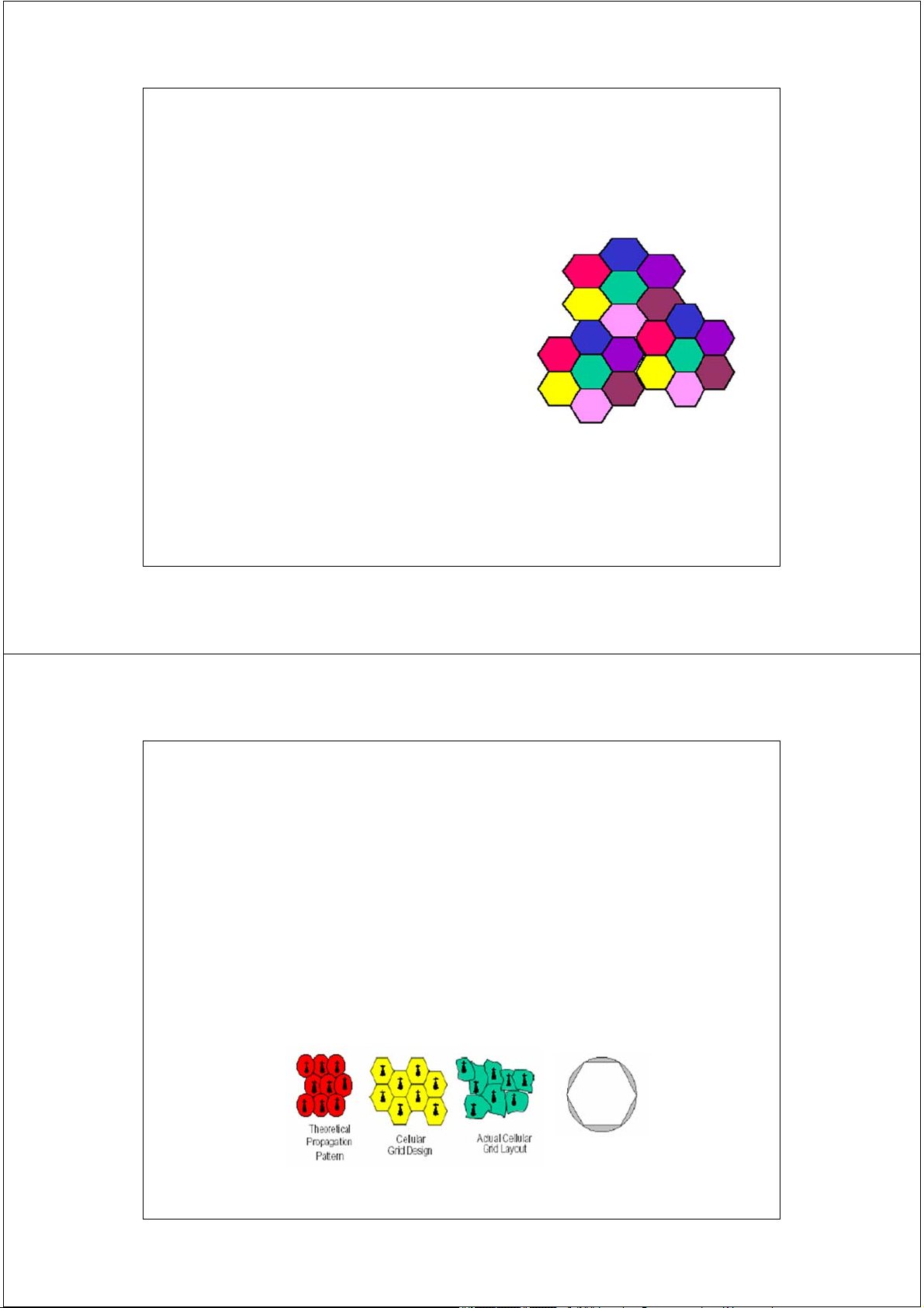
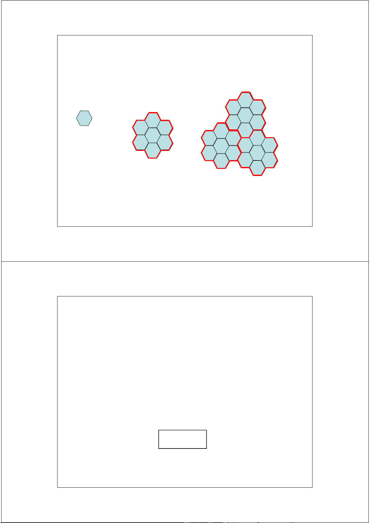
• Geographic Service divided into smaller “cells”
• Neighboring cells do not use same set of frequencies to prevent interference • Often approximate coverage area of a cell by a idealized hexagon • Increase system capacity by frequency reuse. 7 7 2/17/2014 Cellular Networks •
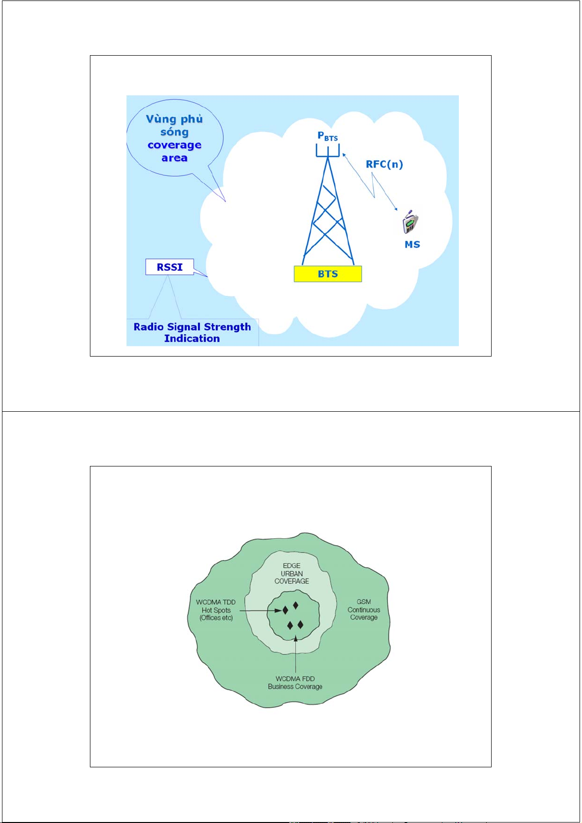
Propagation models represent cell as a circular area •
Approximate cell coverage with a hexagon - allows easier analysis •
Frequency assignment of F MHz for the system •
The multiple access techniques translates F to T traffic channels •
Cluster of cells K = group of adjacent cells which use all of the systems frequency assignment 8 8 2/17/2014 Cellular Concept
• Why not a large radio tower and large service area?
– Number of simultaneous users would be very limited
(to total number of traffic channels T)
– Mobile handset would have greater power requirement
• Cellular concept - small cells with frequency reuse – Advantages • lower power handsets
• Increases system capacity with frequency reuse – Drawbacks: • Cost of cells
• Handoffs between cells must be supported
• Need to track user to route incoming call/message 9 9 2/17/2014 Cellular Concept (cont)
• Let T = total number of duplex channels
K cells = size of cell cluster (typically 9,12, 21)
N = T/K = number of channels per cell
• For a specific geographic area, if clusters are replicated M times, then total number of channels
– system capacity = M x T
– Choice of K determines distance between cells using the
same frequencies => termed “co-channel” cells
– K depends on how much interference can be tolerated by mobile stations and path loss 10 10 2/17/2014 Cell/Site concept 11 2/17/2014 Cell/Site concept 12 2/17/2014
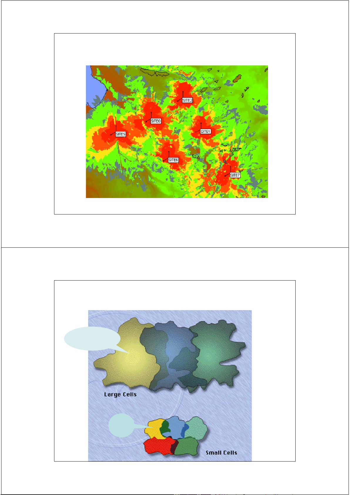
Real Cell/Site Coverage Area 13 2/17/2014
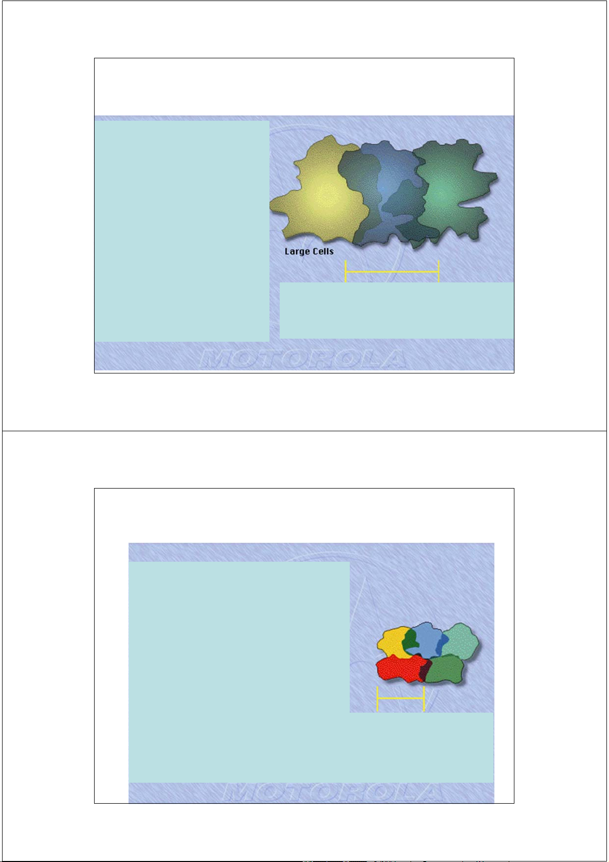
Hình dạng và kích thước ô - cell Cell lớn (Macrocell) Cell nhỏ (Microcell) 14 2/17/2014
Tế bào lớn - Large cell
Vị trí thiết kế các cell lớn:
- Sóng vô tuyến ít bị che khuất ( vùng nông thông, ven biển . . . )
- Mật độ thuê bao thấp
Bán kính phủ sóng ~ n km ÷ n * 10 km
- Yêu cầu công suất phát lớn. ( GSM: <= 35 Km) 15 2/17/2014
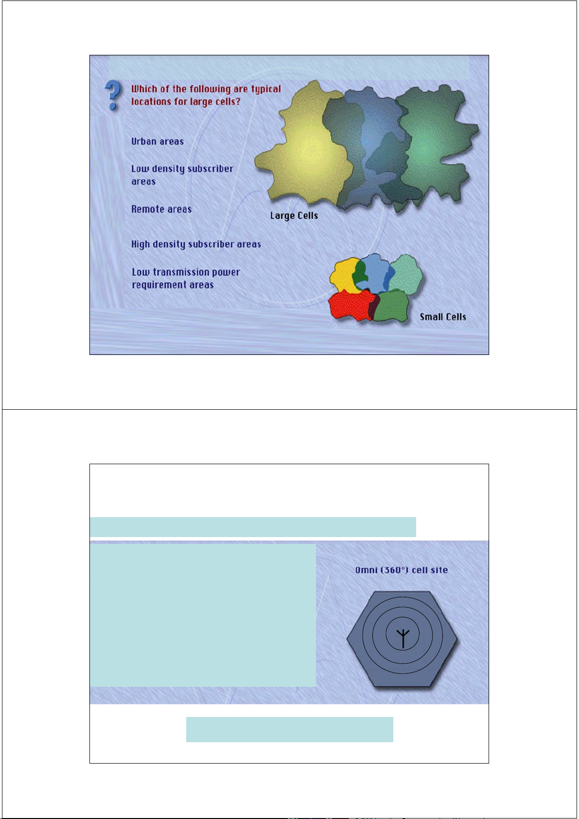
Tế bào nhỏ - Small cell
Vị trí thiết kế các cell nhỏ:
- Mật độ thuê bao cao
- Sóng vô tuyến bị che khuất.
- Yêu cầu công suất phát nhỏ. Bán kính phủ sóng ~ n * 100 m ( GSM: <= 1 Km) 16 2/17/2014 Where to use ? 17 2/17/2014 Phương thức phủ sóng
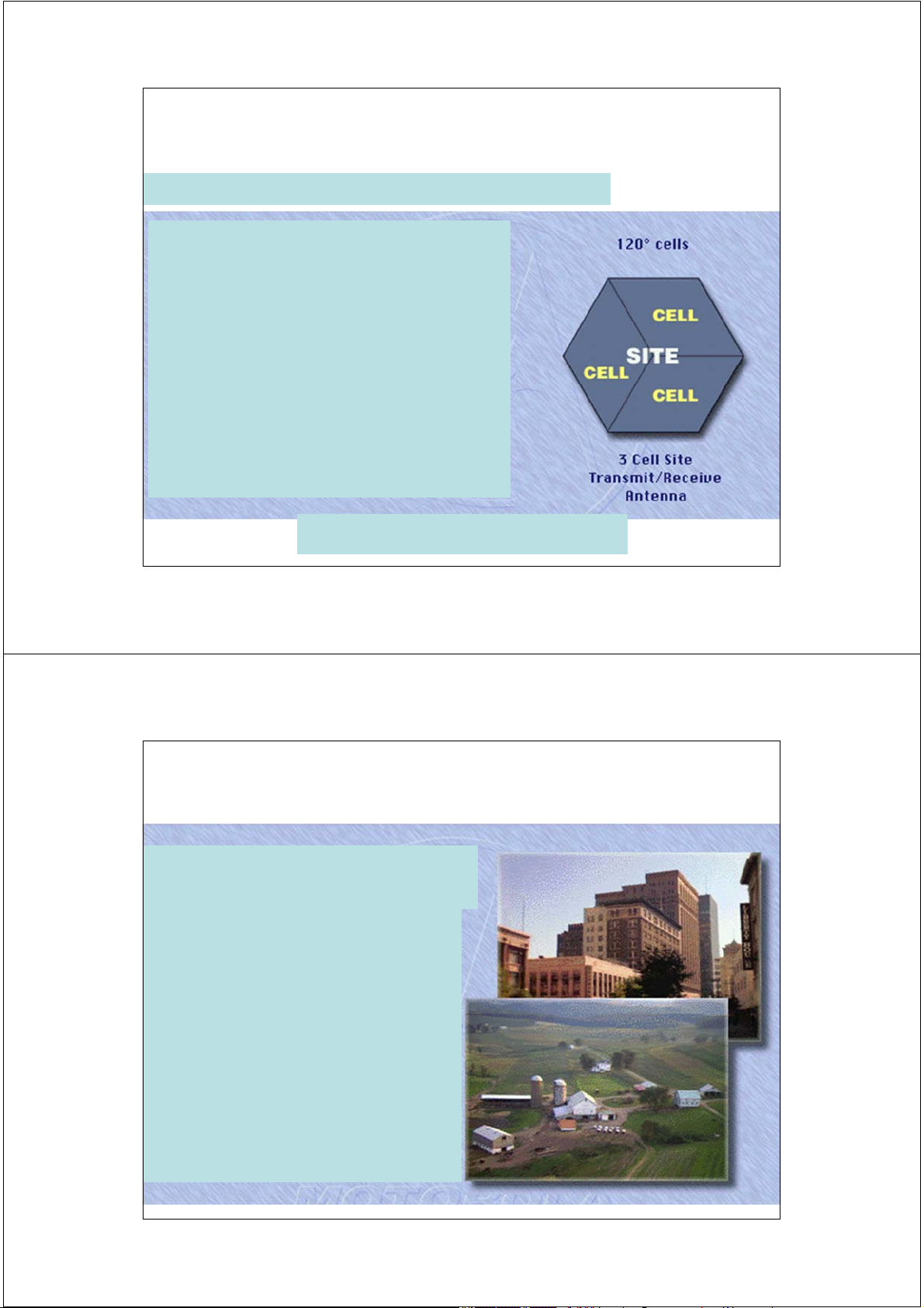
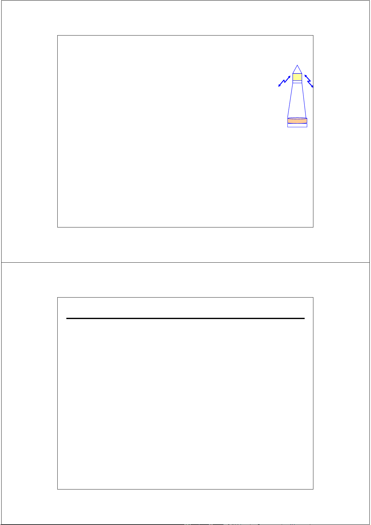
Phát sóng vô hướng - Omni - directional cell (3600 . . .)
- Anten vô hướng hay 3600 bức xạ
năng lượng đều theo mọi hướng. 1 Site = 1 cell 3600 18 2/17/2014 Phương thức phủ sóng
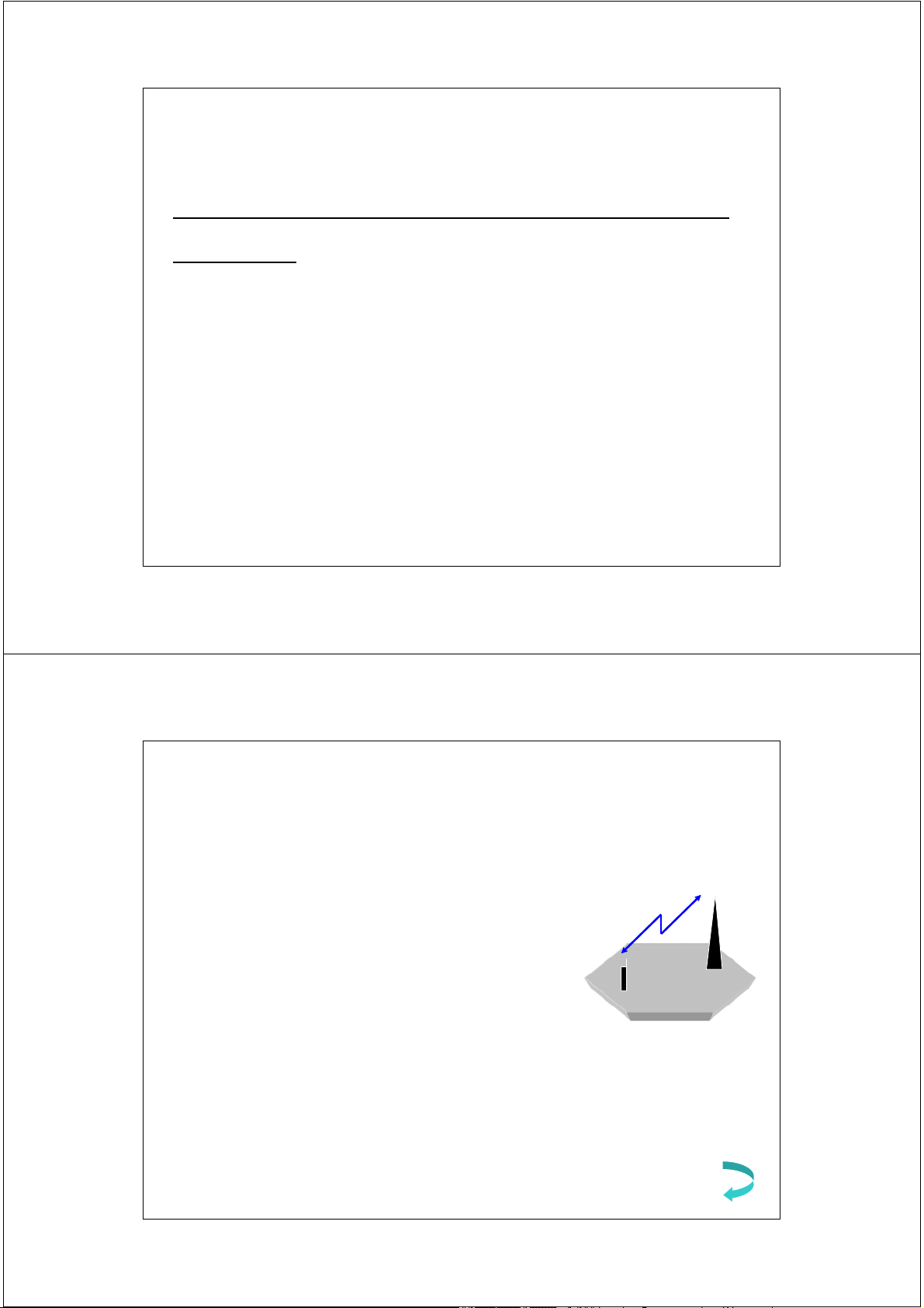
Phát sóng định hướng –> sectorization (1200 . . .)
- Anten có hướng tính sẽ tập trung
năng lượng trong một không gian nhỏ hơn.
- Cải thiện chất lượng tín hiệu.
- Tăng dung lượng thuê bao. 1 Site = 3 cell 1200 19 2/17/2014
Số lượng cell bao phủ một vùng địa lý
Các yếu tố ảnh hưởng đến số lượng
cell trong một vùng địa lý - Mật độ thuê bao
- Yếu tố địa hình : các tòa nhà,
cây cối, hồ nước, đồi núi . . . 20 2/17/2014 Nhận xét
• Trên thực tế, hình dạng cell là không xác định, việc
quy hoạch vùng phủ sóng (coverage area) cần quan
tâm đến các yếu tố địa hình và mật độ thuê bao, từ
đó sẽ xác định số lượng trạm gốc BTS, kích thước
cell và phương thức phủ sóng thích hợp. 21 2/17/2014
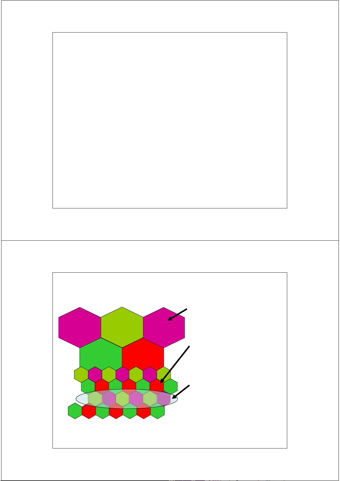
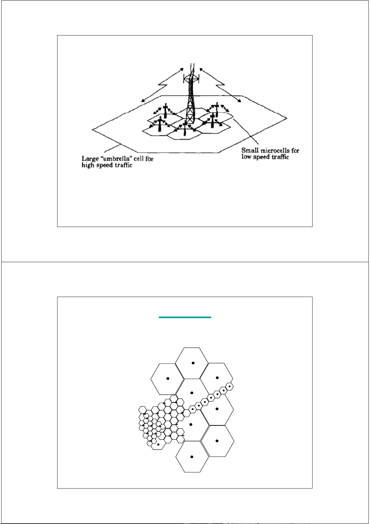
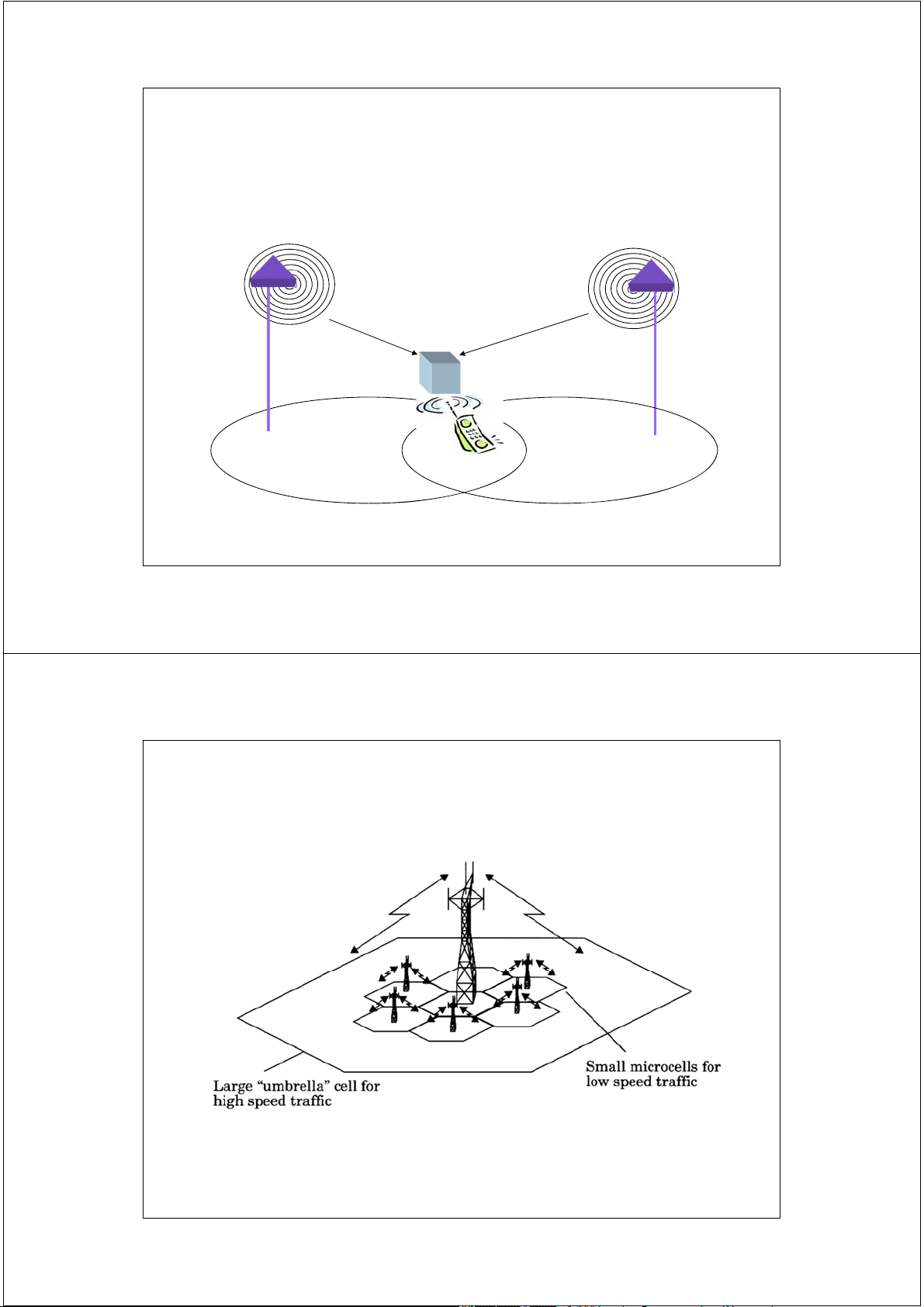
Cellular Concepts: Cells Large cells are used to serve low traffic areas. Microcells are used for high traffic demand regions. Umbrella cells are used in areas where users are moving fast from one cell to another (eg. freeways) 22 2/17/2014
Cellular Concepts: Cells
Umbrella cell : by using different antenna heights (often on the same
building or tower) and different power levels, it is possible to provide
"large" and "small" cells which are co-located at a single location. 23 2/17/2014 Exercise
Considering radio coverage in a PLMN, could you identify the topology of the different areas? 20 20 20 20 40 100 60 60 60 20 100 100 20 60 100 100 20 20 20
Figures indicates Base Stations Erlang capacity 24 24 2/17/2014
Chỉ thị cường độ tín hiệu RSSI RSSI_Max Phạm vi Giá trị ( Range ) ( Value ) Bước dịch chuyển ( Integer steps ) RSSI = 0 25 2/17/2014
Chỉ thị cường độ tín hiệu theo tỷ lệ phần trăm
802.11 NIC : 60 bước chỉ thị RSSI_Max = 60
Giá trị chỉ thị = 50 % -> RSSI = 30
Ưu điểm của chỉ thị % - Phân tích mạng - Thống kê RSSI = 0 26 2/17/2014 Đơn vị công suất
P W <=> dB; mW <=> dBm P (dBm) = 10 log10 [ P (mW)] P(mW) P(dBm) P(dBm) = P(dB) + 30 10 10 1 0 20 W => ? dBm 10-1 -10 10-2 -20 33 dBm => ? W 27 2/17/2014
Chuyển đổi giá trị chỉ thị cường độ tín hiệu
theo tỷ lệ phần trăm sang dBm
Hai bước ánh xạ RSSI [ x % ] sang dBm
1. Xác định RSSI_Max của nhà sản xuất – Vendor.
-> RSSI[x %] = x (%) * RSSI_Max / 100
2. Tra giá trị dBm tương ứng với giá trị RSSI vừa xác định
trong bảng chuyển đổi hoặc công thức chuyển đổi do nhà sản xuất cung cấp.
[*] Lưu ý: bảng chuyển đổi không phải khi nào cũng biến đổi
theo quy luật tuyến tính. 28 2/17/2014
Chuyển đổi giá trị chỉ thị cường độ tín hiệu theo tỷ lệ phần trăm sang dBm Ví dụ:
• Atheros: RSSI_Max =60; -> dBm = RSSI – 95;
• Phạm vi biến đổi của dBm : -35dBm đến -95 dBm
• Cường độ tín hiệu thu nhận tại 802.11 NIC là x = 30 %
tương ứng với công suất thu là bao nhiêu dBm ?
• RSSI[30%] = 30 * 60 / 100 = 18
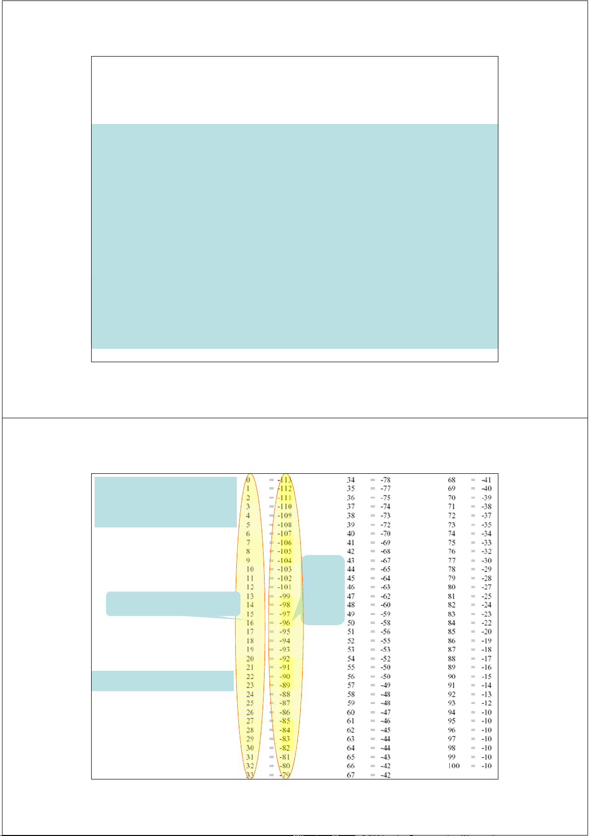
• dBm = RSSI[30%] - 95 = 18 – 95 = -77 (dBm) 29 2/17/2014 Bảng chuyển đổi RSSI-dBm của Cisco Giá trị Giá trị RSSI. dBm RSSI_Max = 100 30 2/17/2014
Chuyển đổi giá trị chỉ thị cường độ tín hiệu theo tỷ lệ phần trăm sang dBm Ví dụ:
• Cisco: RSSI_Max =100;
• Phạm vi biến đổi của dBm: -10 dBm đến -113dBm
• Cường độ tín hiệu thu nhận tại 802.11 NIC là x = 30 %
tương ứng với công suất thu là bao nhiêu dBm ?
• RSSI[30%] = 30 * 100 / 100 = 30 -> tra bảng:
• dBm = RSSI[30%] = - 82 (dBm) 31 2/17/2014
Độ nhạy thu - Receive Sensitivity Khái niệm:
• Độ nhạy thu là mức công suất tối thiểu mà tại đó máy thu
vẫn nhận được tín hiệu với mức độ chất lượng xác định • Đơn vị: [dBm] Ví dụ:
• Card mạng WLAN theo chuẩn 802.11 có độ nhạy thu là -96 dBm ~ ? mW
-96 (dBm) ~ 0.0000000002511 (mW) 32 2/17/2014
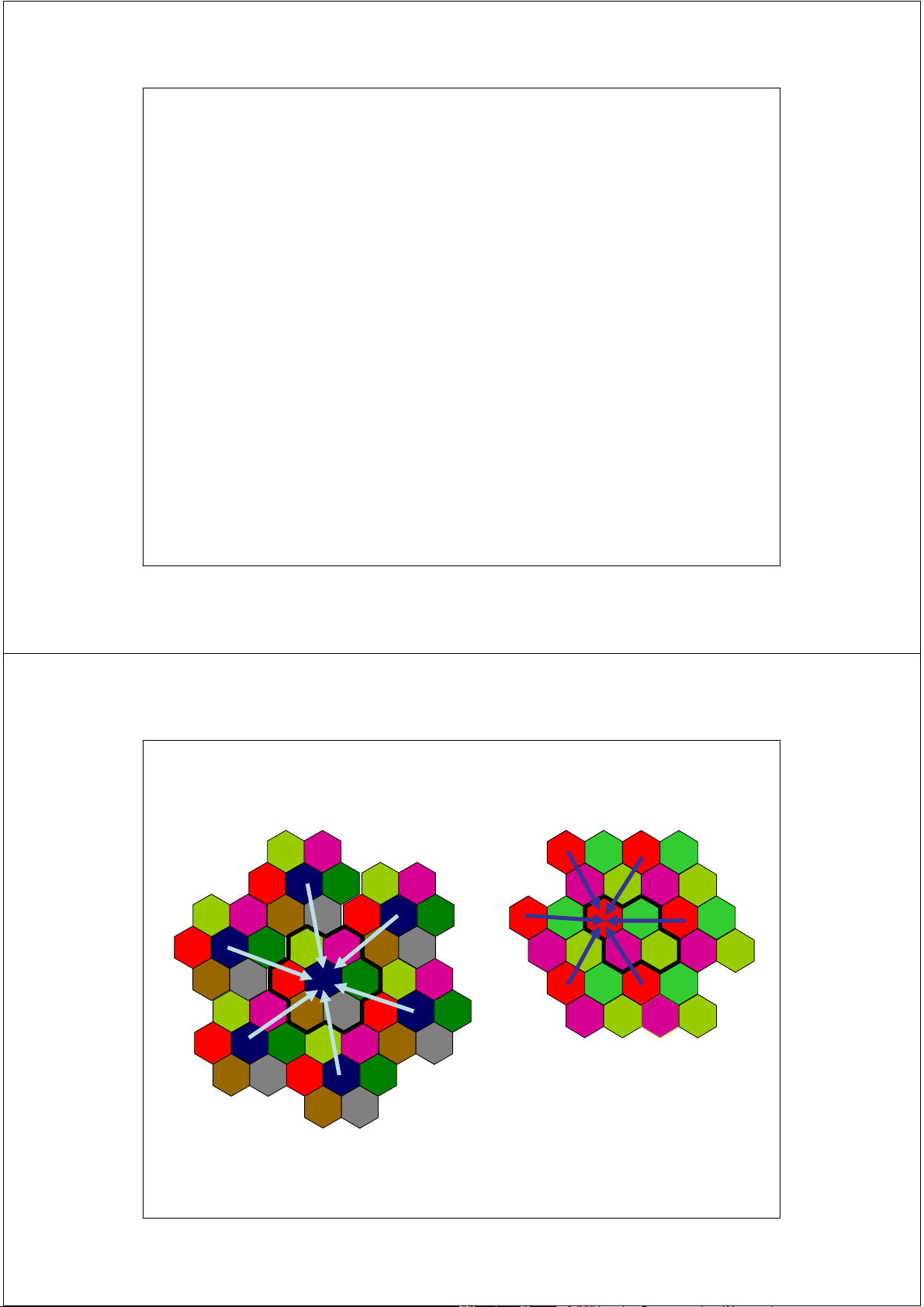
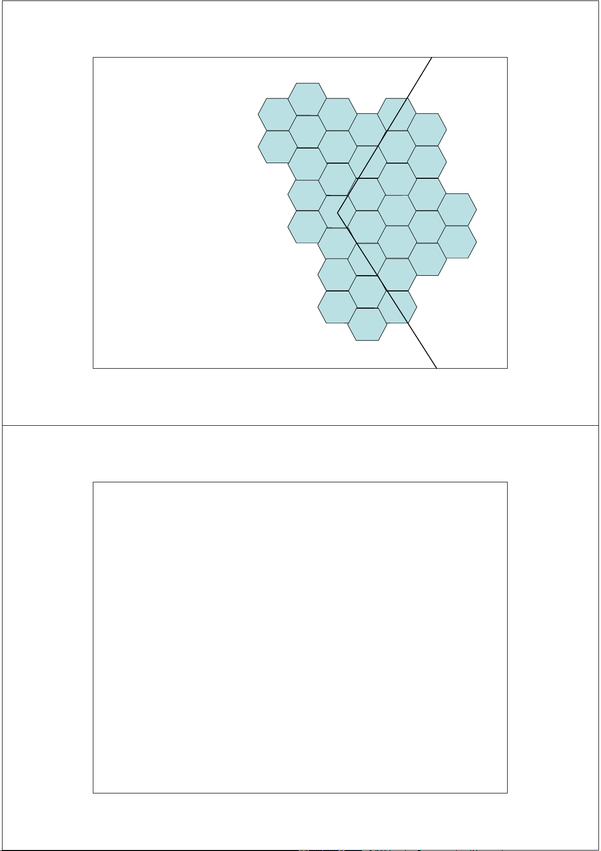
Sử dụng lại tần số
Cellular Frequency Reuse B G C A B F D G C B E A Cell G C B F D A G C E F D A E F D Cell cluster E
Mục đích: tăng dung lượng hệ thống ( increase capacity) 33 2/17/2014
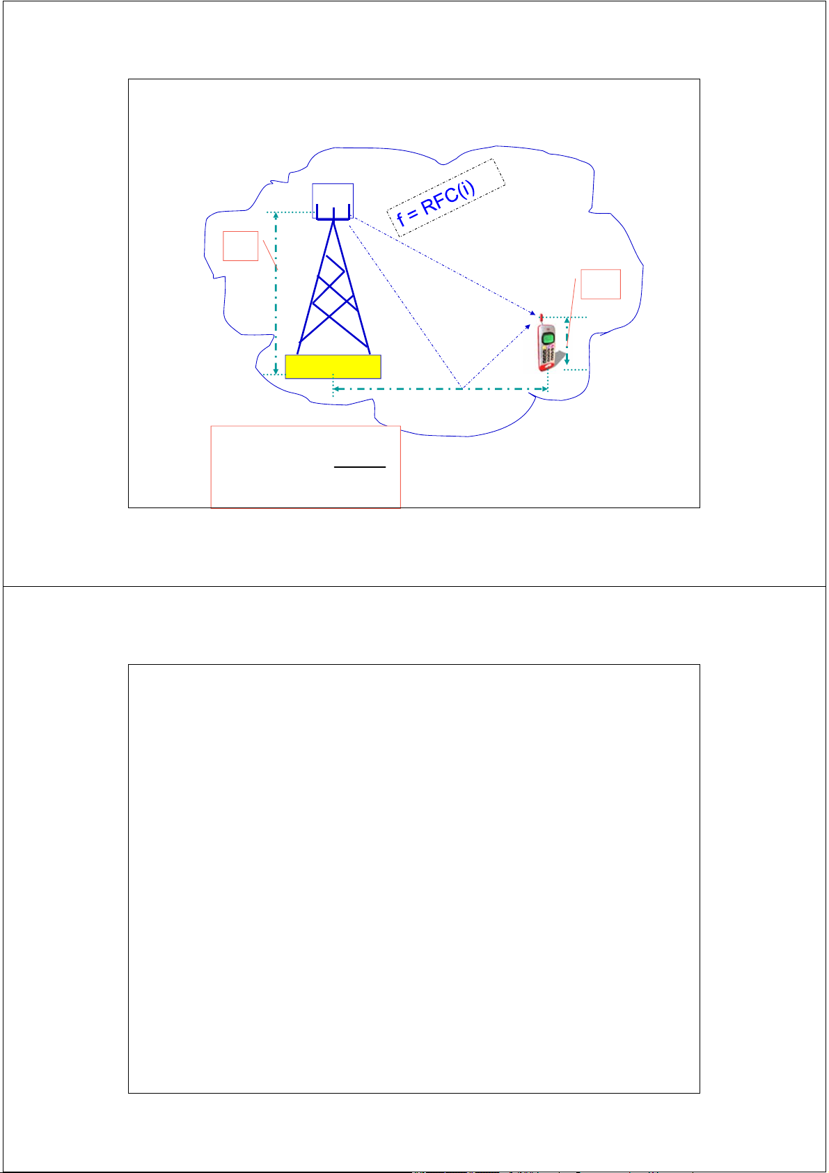
Sử dụng lại tần số
• Hệ thống Cellular bao gồm S kênh vô tuyến - RFC
( RFC: Radio Frequency Channel)
• Mỗi cell được cấp phát k RFC ( k < S )
• S kênh được chia sẻ cho N cells. S = kN 34 2/17/2014
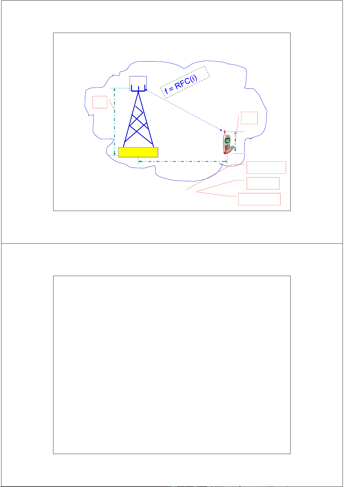
Sử dụng lại tần số
• N cells hình thành một cluster (N cluster size)
• Một cluster được lặp lại M lần trong một hệ thống
cellular tại các vị trí địa lý khác nhau
• Khi đó dung lượng hệ thống C = tống số kênh RFC trong hệ thống (capacity) C = MkN = MS 35 2/17/2014
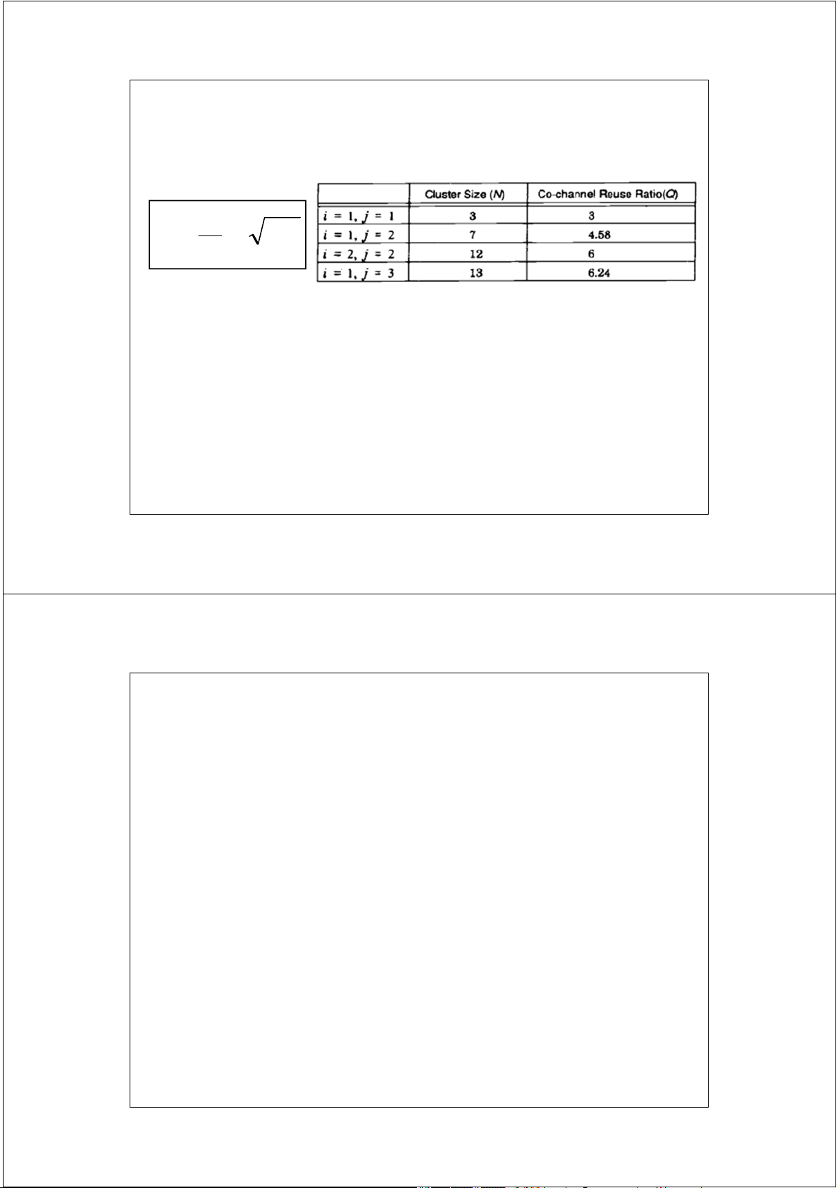
Sử dụng lại tần số
• Thông thường cluster có kích thước N = 4, 7, 12
• Với : N = i2 + ij + j2 A
• Cell sử dụng cùng kênh tần số
• Co-channel – đồng kênh A
• Cần có sự thỏa hiệp giữa : A
dung lượng và nhiễu
[ Trade-off : capacity vs interference ] 36 2/17/2014 Ví dụ 1.1
If a total of 33 MHz of bandwidth is allocated to a particular
FDD cellular telephone system which uses two 25 kHz
simplex channels to provide full duplex voice and control
channels, compute the number of channels available per cell if a system uses
(a) 4-cell reuse, (b) 7-cell reuse (c) 12-cell reuse. 37 2/17/2014
Mẫu sử dụng lại tần số
Ký hiệu tổng quát : mẫu N/M Trong đó: N = tổng số site / cluster M = tổng số cell / cluster
• Hệ số sử dụng lại tần số: 1/M
=> Mỗi cell được cấp phát 1/M tổng số kênh tần
số vô tuyến trong 1 cluster . 38 2/17/2014 Các nguồn nhiễu Sources of Interference
• Intra cell: Nhiễu từ các MS khác trong cùng cell.
• Inter cell: Nhiễu tức các MS đang tiến hành gọi từ các cell
lân cận ( neighboring cell )
• Nhiễu từ các trạm gốc sử dụng cùng băng tần.
• Nhiễu từ các hệ thống khác - Noncellular systems 39 2/17/2014
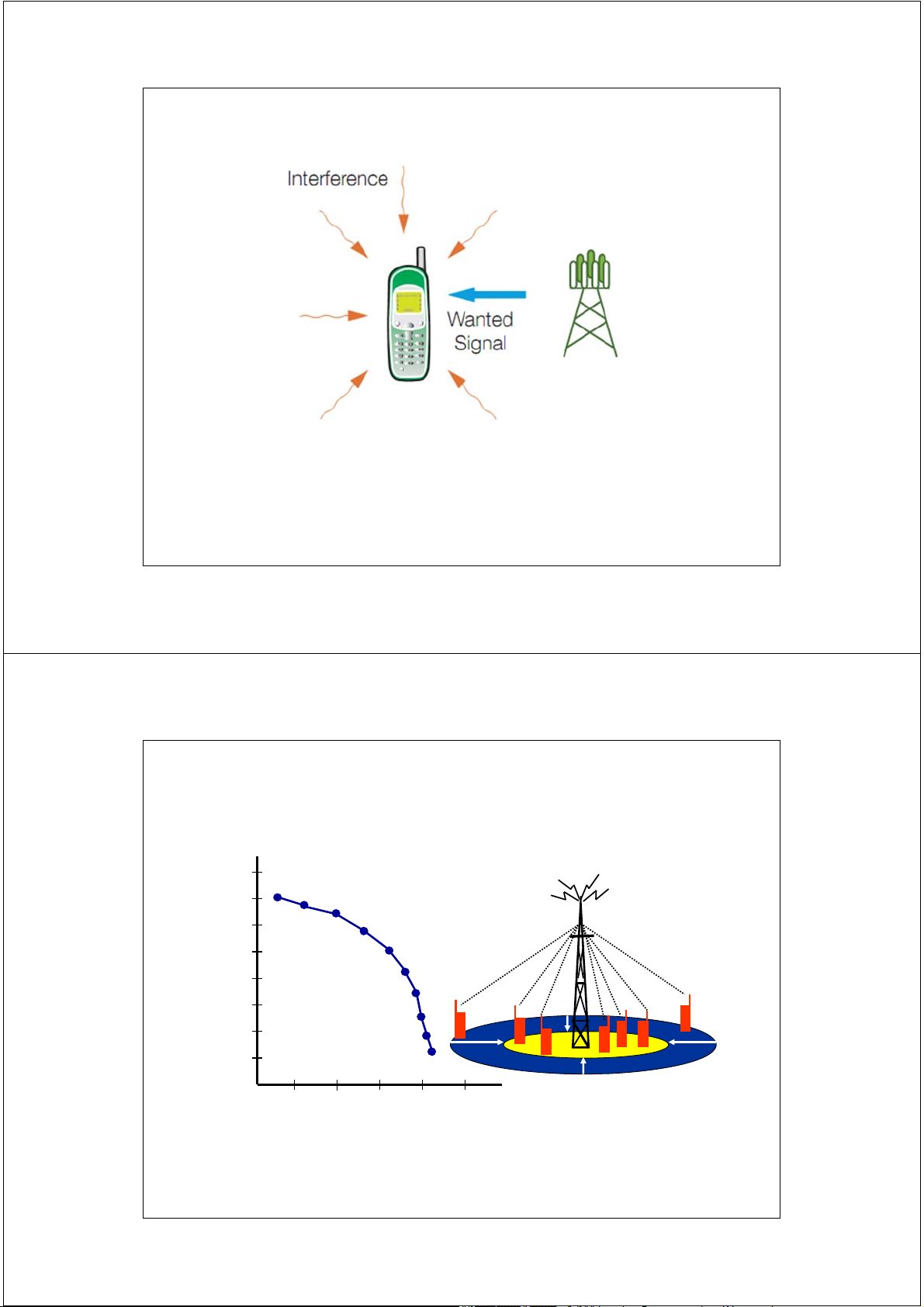
Interference and System Capacity
• Interference is a limiting factor in the performance of cellular systems
• Co-Channel interference (CCI) is caused by signals at the same frequency
• Adjacent channel interference (ACI) is caused by signals from neighbouring frequencies
• In traffic channels, interference causes crosstalk from undesired users
• In control channels, interference causes errors which result in wrong instructions
• To reduce co-channel interference, co-channel cells must be separated sufficiently 40 40 2/17/2014 Nhiễu đồng kênh Co-Channel Interference • Co-Channels:
• Các cells sử dụng cùng kênh tần số
• Nhiễu đồng kênh : Co-Channel Interference:
• Gây nên do việc sử dụng lại tần số (cell reuse)
-> Interference between ”Co-cells”
• Phương thức giảm nhiễu đồng kênh:
• Tăng khoảng cách sử dụng lại tần số. • Tăng tỷ số SNR. 41 2/17/2014 Co-channel Interference 4-cell frequency reuse (stronger)
7-cell frequency reuse (weaker) 42 2/17/2014
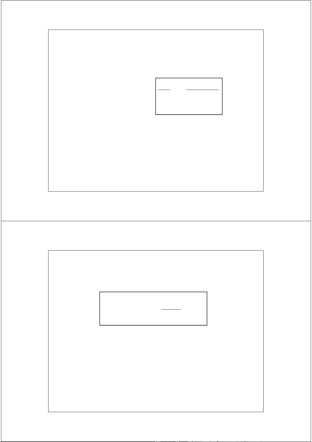
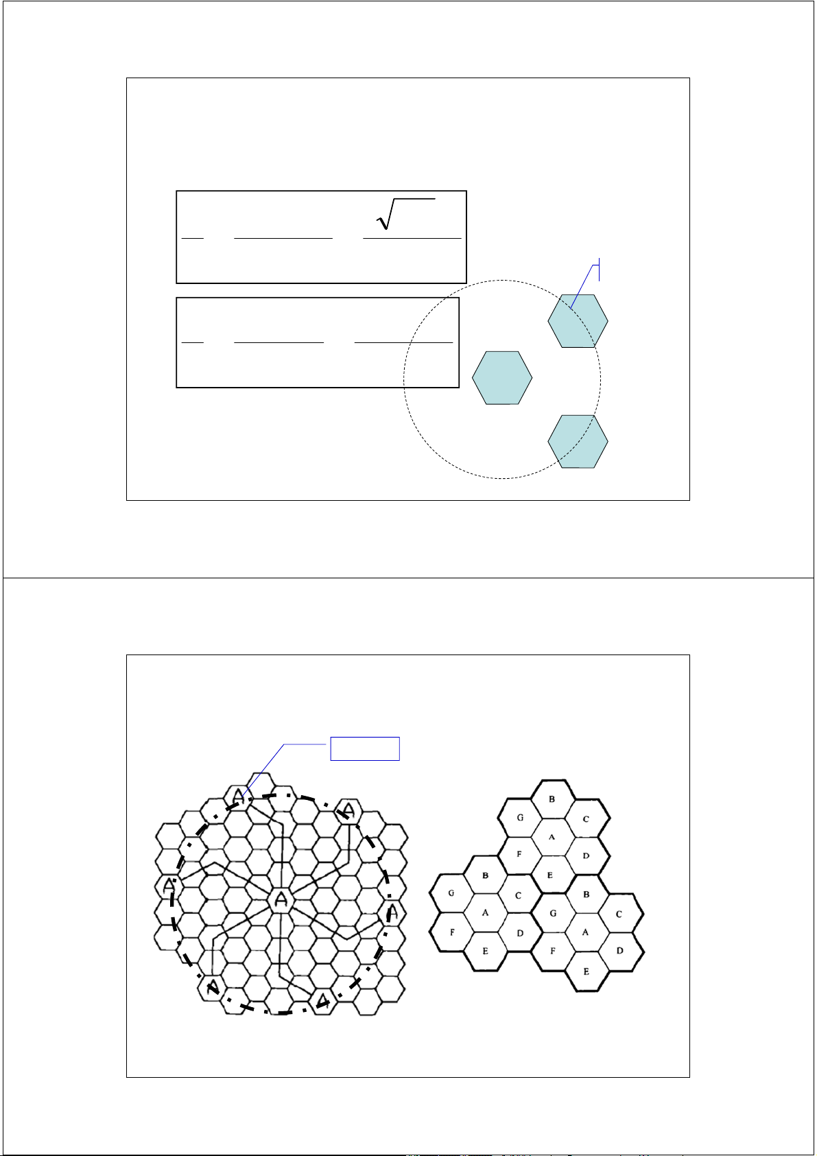
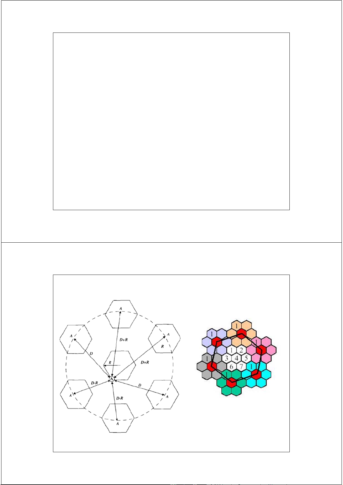
Hệ số tái sử dụng tần số Co-Channel Reuse Ratio D Q 3N R
• D = Khoảng cách giữa tâm hai cell đồng kênh gần nhất. • R= Bán kính cell • N= Kích thước cluster
• Q nhỏ: Dung lượng tăng ( N giảm )
• Q lớn: Chất lượng truyền dẫn vô tuyến tốt hơn. 43 2/17/2014
Tỷ số tín hiệu trên nhiễu
Signal-to-Interference Ratio
• In general Signal-to-Interference ratio can be written as;
Sr= Pdesired / Σi Pinterference,i
• Pdesired is the signal from the desired BS and Pinterference,i is
the signal from the ith undesired BS
• The signal strength falls as some power of α called
power-distance gradient or path loss component
• If Pt is the transmitted power, d is the distance then, received power will be Pr=Pt L d-α Where, d is in meters
L is the constant depending on frequency 44 44 2/17/2014
Tỷ số tín hiệu trên nhiễu
Signal-to-Interference Ratio S S S/I (SIR): I i0 I i i 1
• S: Công suất tín hiệu mong muốn
• Ii: Công suất tín hiệu nhiễu từ kênh cùng tần số thứ i 45 2/17/2014
Công suất thu trung bình Average Received Power n d P P r 0 d 0
Pr(dBm)=P0(dBm) - 10nlog(d/d0)
• P0: Công suất thu tại khoảng cách tham chiếu d0
• n: Hệ số tổn thất đường truyền, 2* Với các hệ thống cellular n ≈ 4 46 2/17/2014
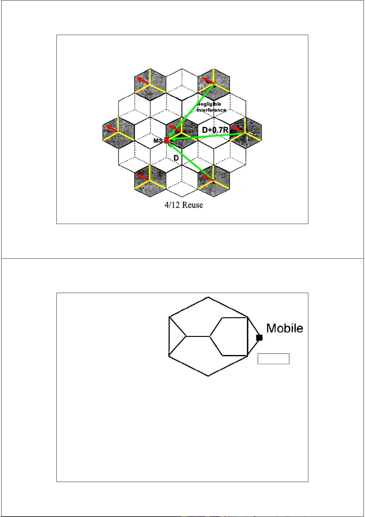
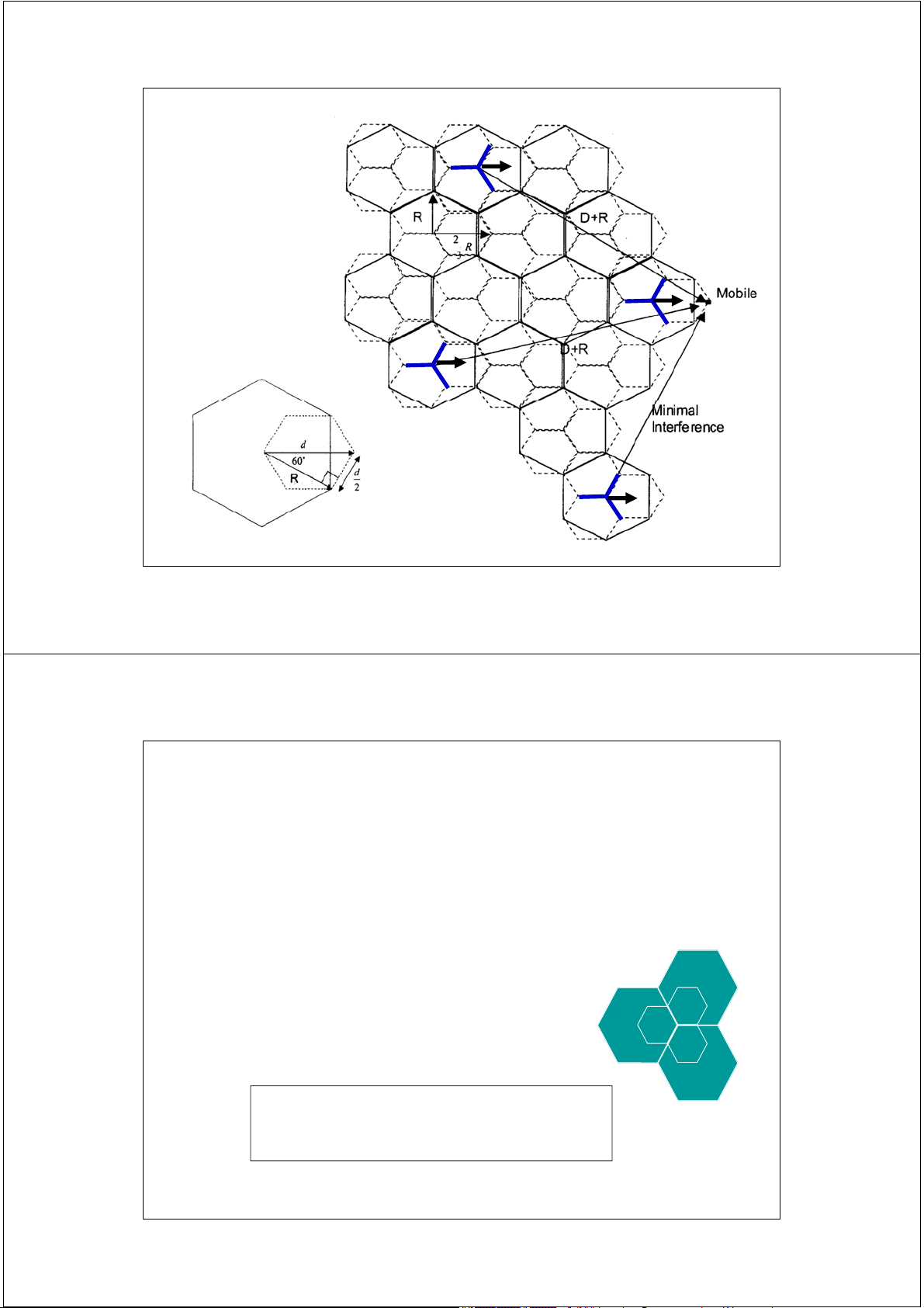
Lớp nhiễu đồng kênh thứ nhất
First Layer of Co-Channels S (D / R)n ( 3N )n I 0 i 0 i first tier S P Rn (D / R)n t I n 0 i P D t 0 i 47 2/17/2014
Sử dụng lại tần số first tier 48 2/17/2014 Ví dụ 1.2
If a signal to interference ratio of 15 dB is required for satisfactory
forward channel performance of a cellular system, what is the frequency
reuse factor and cluster size that should be used for maximum capacity if the path loss exponent is
(a) n = 4 , (b) n = 3?
Assume that there are 6 co-channels cells in the first tier, and all of them
are at the same distance from the mobile. Use suitable approximations. 49 2/17/2014 Ví dụ 1.3: CIR ? first tier co-channel interference 50 2/17/2014 Ví dụ 1.4
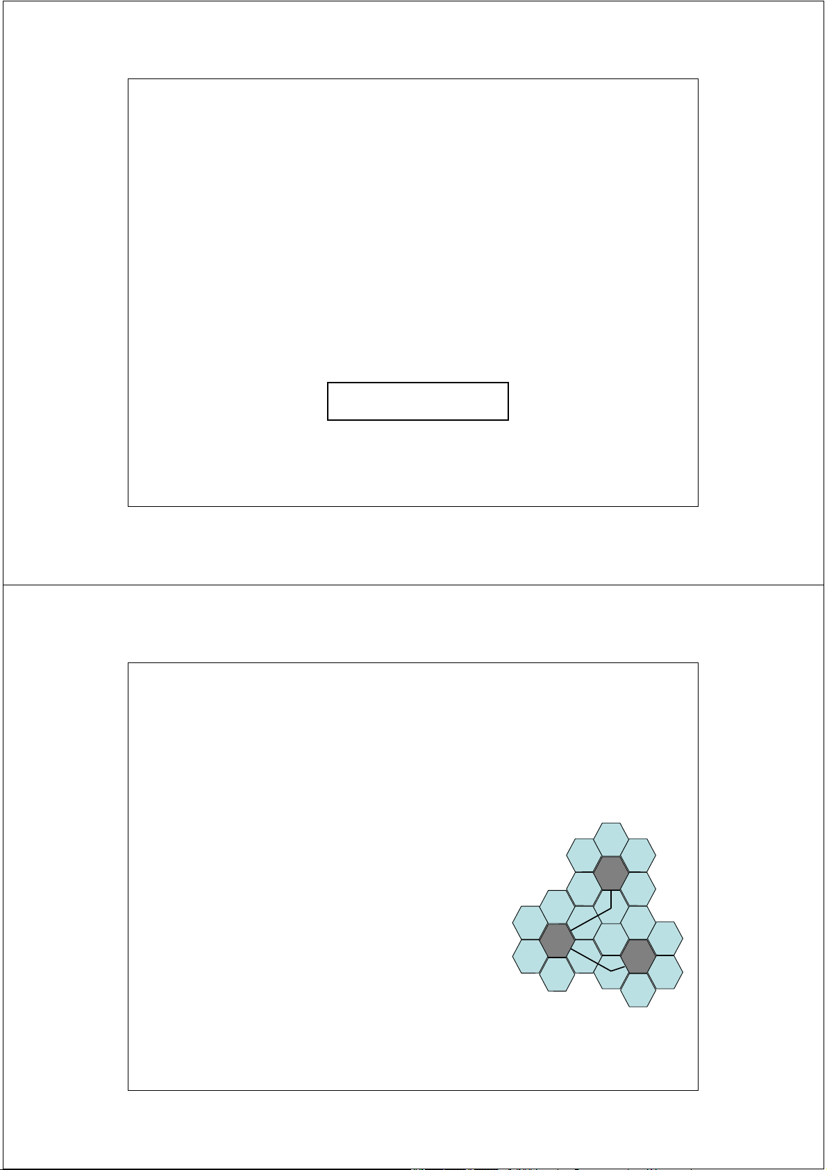
Measurements of a cellular network show that there is significant
interference in a particular location in the network. It is identified that
there are 6 main interfering base stations and that they are located at a
distance of 8.15 km, 8.3km, 7.9 km, 7.7 km , 7.5 km and 8.9 km
respectively from the location of the test mobile. The distance from the
test mobile to wanted cell is 2.7 km. Estimate the Carier to Interfence Ratio at the mobile.
Use a path loss exponent of n = 3.5 51 2/17/2014
Improving Capacity in Cellular Systems •
Aim: To provide more channels per unit coverage area •
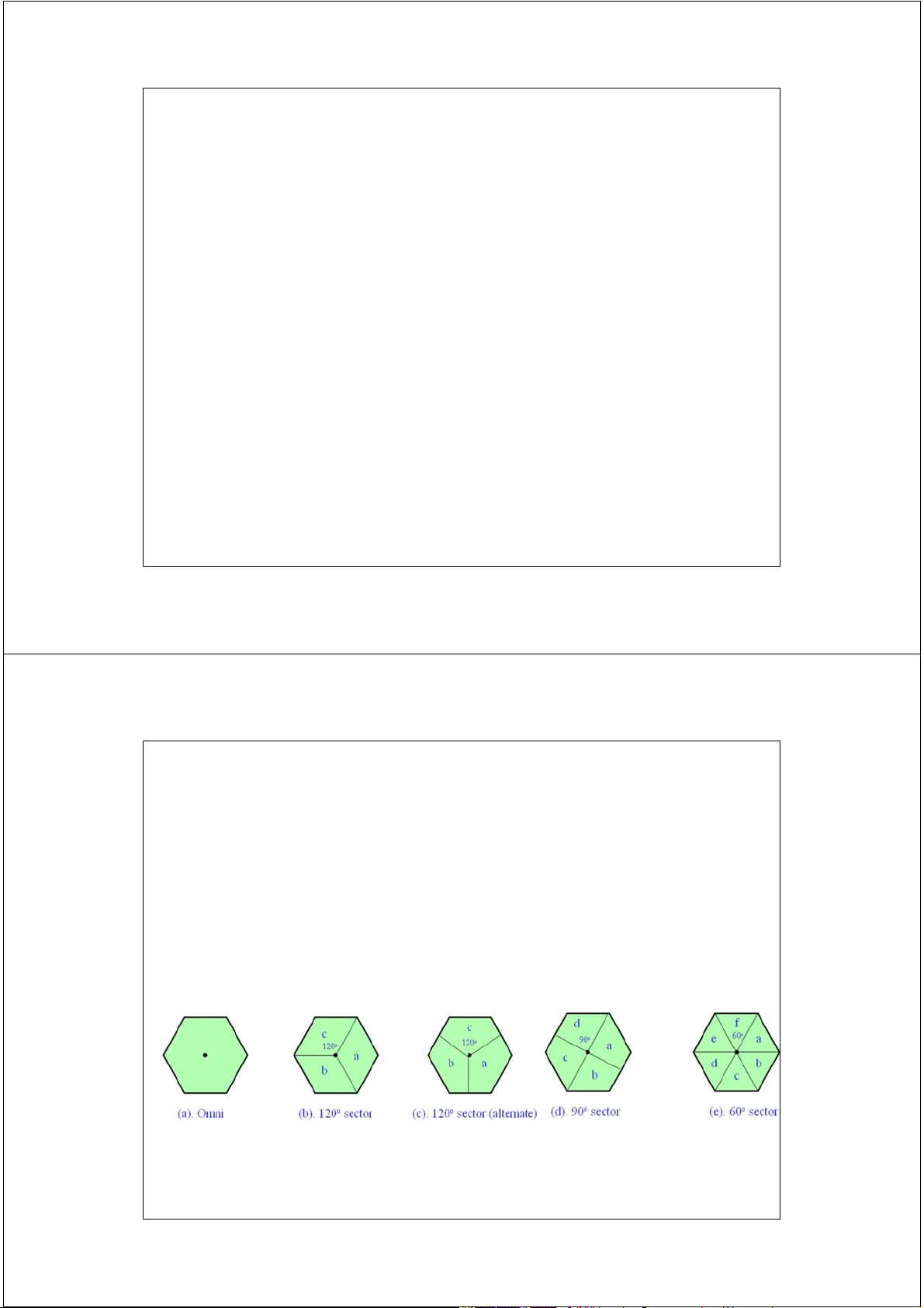
Techniques: Three techniques are used to improve capacity • SECTORING: –
Use directional antennas to further control the interference and frequency reuse of channels. –
Examples: Omni, 120O, 60O and 90O 52 52 2/17/2014 Sectored Cells
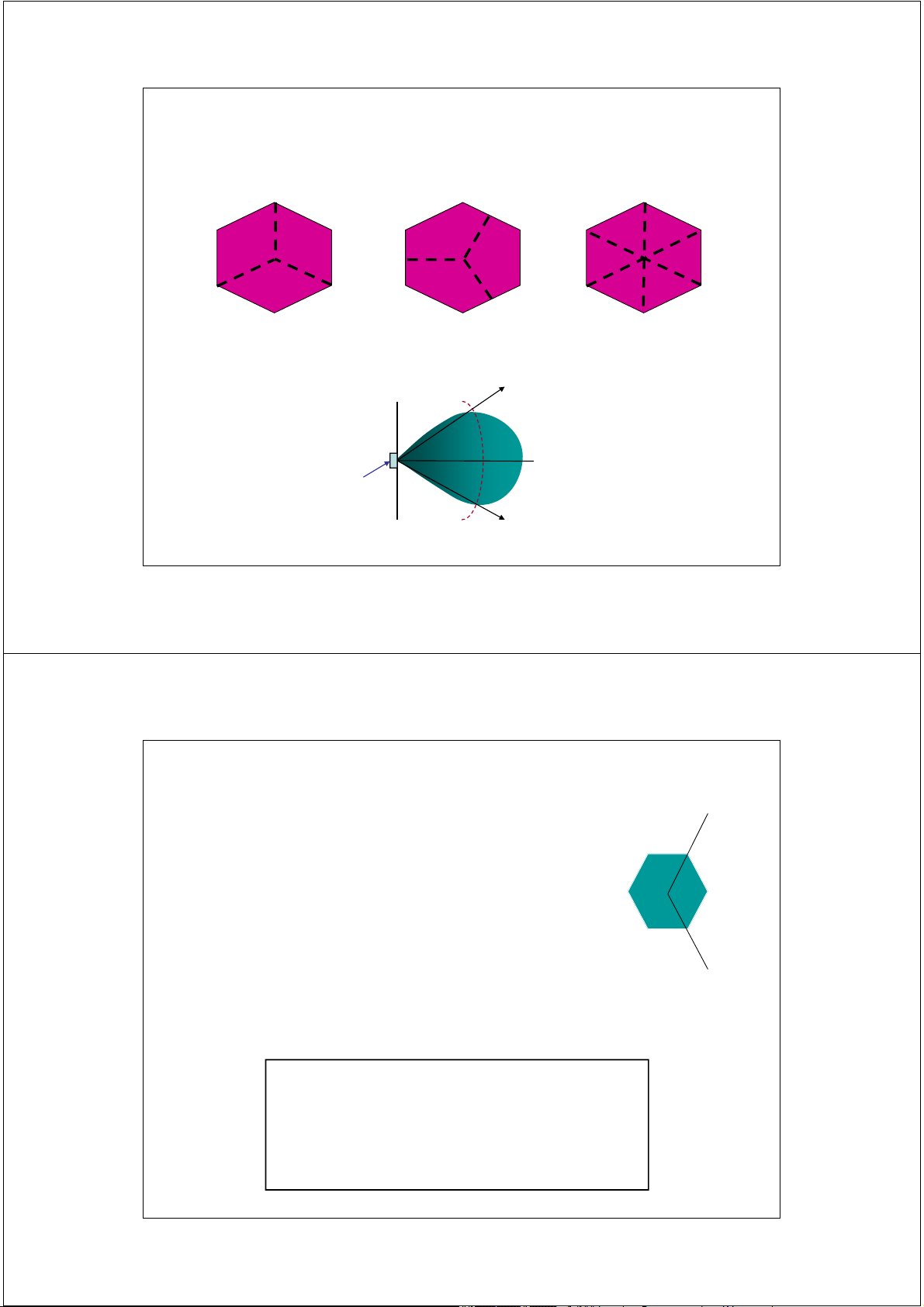
• Some commonly used sectored cells: Rhombic Hexagonal Triangular
• The output power of an antenna in a sectored cell: coverage antenna -3dB 53 2/17/2014 Sectoring
• Anten định hướng - Directional
• Phân dải quạt : 60º hoặc 120º/sectors
• Giảm nhiễu - interferers • SIR tăng • Cần bổ sung anten 120º sectoring • Increase SIR
Decrease cluster size Increase capacity 54 2/17/2014 Sectoring improves SIR 55 2/17/2014 Sectoring improves SIR 56 2/17/2014 Phân dải quạt B Sectoring G C B A G C F D A Phân cung hóa E F D B E Sectorization G C B A G C F D A E F D EIRP (dBi) B E G C ERP = EIRP + 2.15 (dB) A F D E
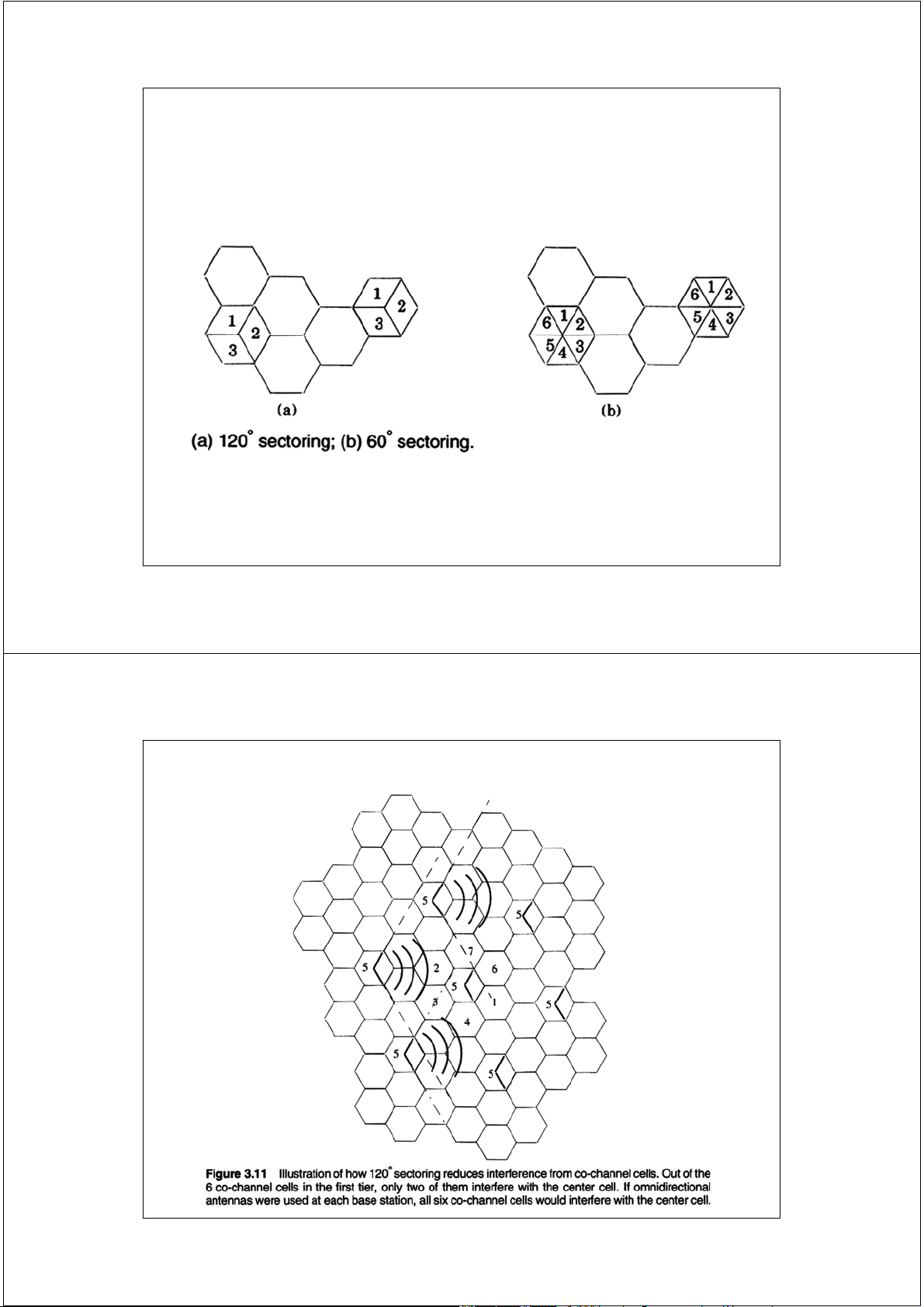
EIRP: Effective Isotropic Radiated Power 57 2/17/2014 Sectoring
• The sectoring is done by replacing a single omni-directional antenna
with 3 directional antennas (120O sectoring) or with 6 directional antennas (60O sectoring)
• In this scheme, each cell is divided into 3 or 6 sectors. Each sector
uses a directional antenna at the BS and is assigned a set of channels.
• The number of channels in each sector is the number of channels in
a cell divided by the number of sectors. The amount of co-channel
interferer is also reduced by the number of sectors. • Drawbacks:
• Increase the number of antennas at each BS
• The number of handoffs increases when the mobile moves from one sector to another. 58 58 2/17/2014 Ví dụ 1.5: CIR ? 59 2/17/2014 Ví dụ 1.6 Figure 1
An omnidirectional cell cluster is sectored using hexagonal sectors as shown in the figure 1.
a. Skecth the cell plan for a 7-cell reuse cluster identifying the strongest
interference base stations to the mobile located as in Fig .1
b. Identify on the cell plan for (a) the approximately distances from those
strongest interfering base stations to the mobile
c. Calculate the carrier to interference ratio using the information in (a) and
(b) . Take the path loss exponet to be n = 4. 60 2/17/2014 61 2/17/2014 Chia cell Cell Splitting
• Chia cell hiện tại thành nhiều cell có diện tích nhỏ hơn
• Giảm chiều cao anten và công suất phát
• Tăng số kênh sử dụng lại tần số ( Increase channel reuse ) • More base stations
• Co-channel interference constant 62 2/17/2014 Cell Splitting 63 2/17/2014 Cell splitting 64 2/17/2014 Cell Splitting
• Cell splitting is the process of splitting a mobile cell into several
smaller cells. This is usually done to make more voice channels
available to accommodate traffic growth in the area covered by the original cell
• If the radius of a cell is reduced from R to R/2, the area of the cell is
reduced from Area to Area/4. The number of available channels is also increased.
• Cell splitting is usually done on demand; when in a certain cell there
is too much traffic which causes too much blocking of calls. The cell
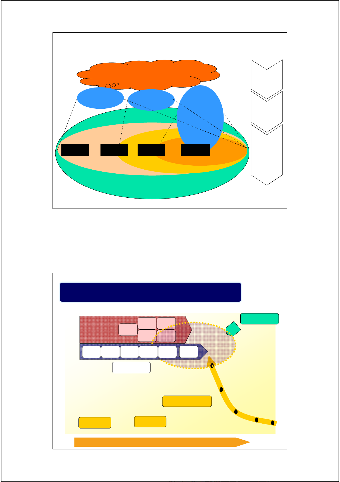
is split into smaller microcells. 65 65 2/17/2014 Paradigm From 1G to Beyond 3G Beyond Third First Generation Second Generation Third Generation Generation • Analogue • Digital • Circuit switched • Digital • Packet and circuit • Digital • Basic voice • Circuit switched switched • Packet switched telephony • Voice plus basic • Advanced data • All IP based (IPv6) • Low capacity data applications (multimedia) • More advanced • Limited local • Low data speed applications multimedia and regional • Enhancements • Fast data access applications coverage towards • User in control • packet switching • Global coverage • Flexible platform • higher data rates • Global roaming • Trans-national of complementary and global access systems roaming • High speed data • Improved QoS • Global coverage • Global roaming 66 2/17/2014
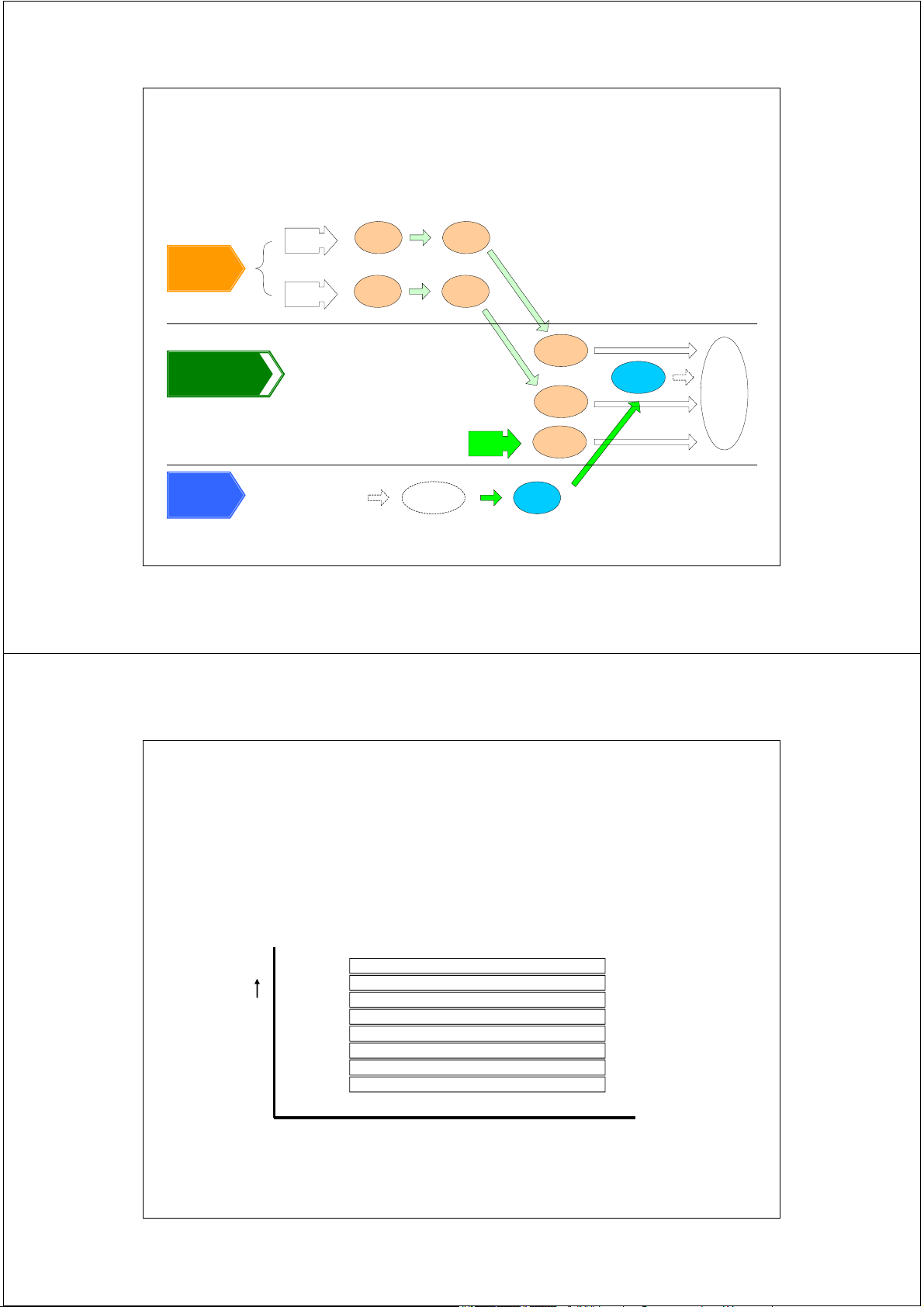
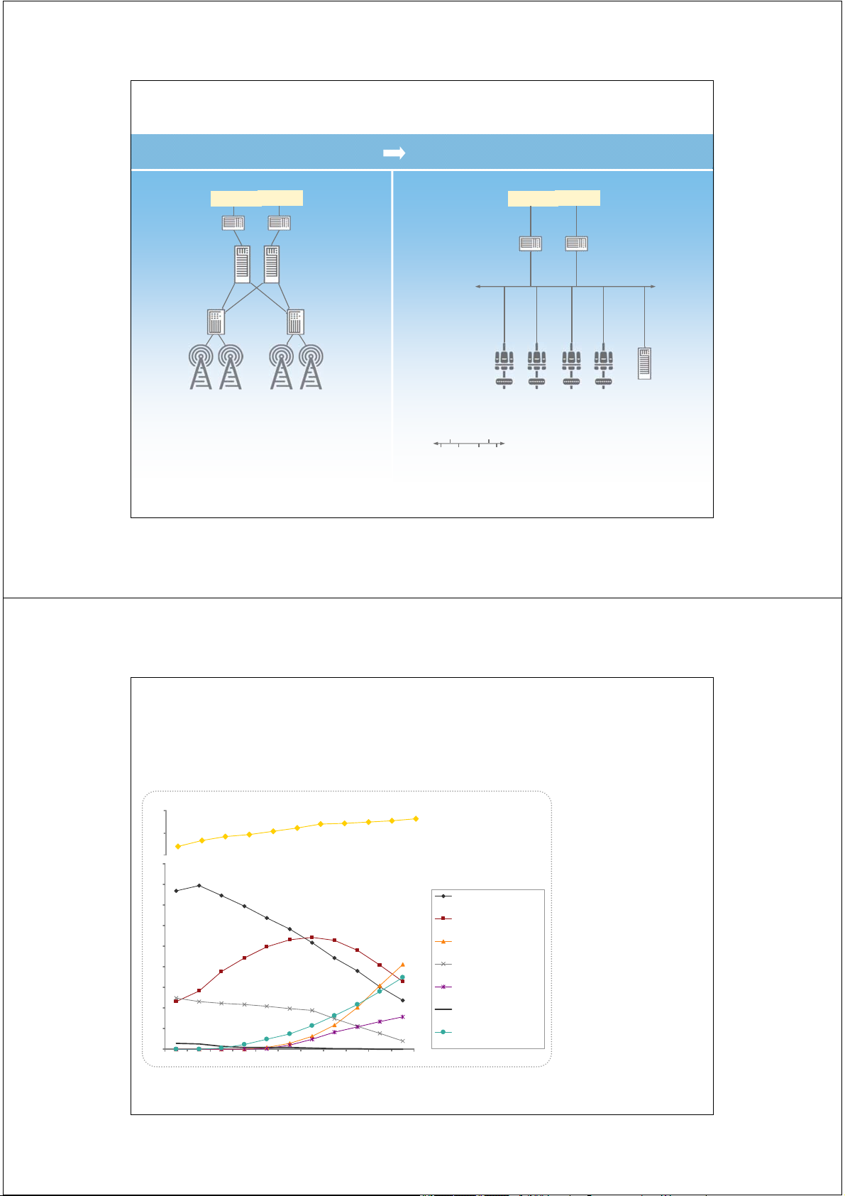
Evolution of Wireless Communications 1st Generation 2nd Generation 3rd Generation 4th Generation Analog Digital Wideband Wideband All-IP CDMA North AMPS Notes: America IS-95 IP: Internet Protocol Voice
TCP: Transmission Control Protocol Service
AMPS: Advanced Mobile Phone Services
ETACS: European Total Access Communication System Track
PDMA: Packet Division Multiple Access (Hanwang, China) ETACS GSM Europe Circuit Switching CDMA 2000 Voice & Data Service PDMA Circuit and Packet Switching Track evolving to Packet Switching 4G WCDMA TD- China SCDMA Data Fixed Service Computer WLAN Network Track Packet Switching 67 2/17/2014 1G — Separate Frequencies
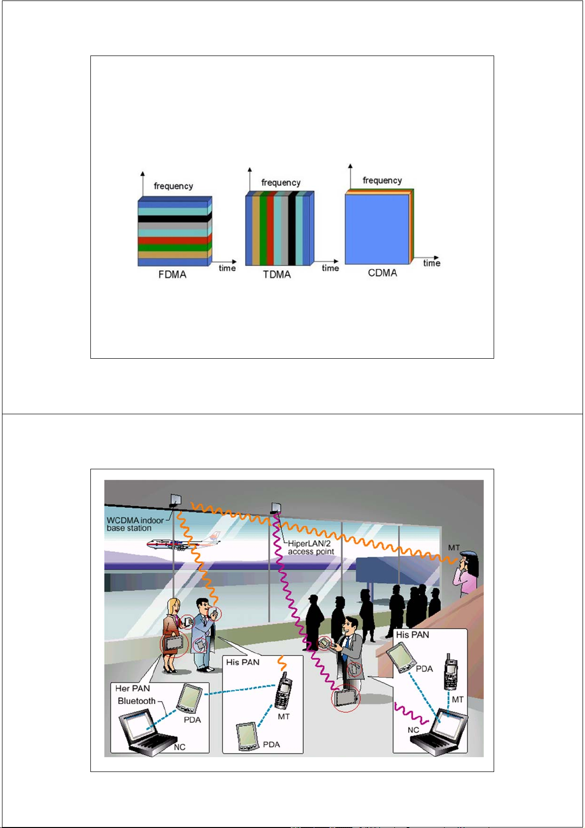
FDMA — Frequency Division Multiple Access 30 KHz 30 KHz 30 KHz 30 KHz 30 KHz 30 KHz 30 KHz Frequency 30 KHz 68 2/17/2014 2G — TDMA
Time Division Multiple Access One timeslot = 0.577 ms One TDMA frame = 8 timeslots 200 KHz 200 KHz 200 KHz Frequency 200 KHz Time 69 2/17/2014 2G & 3G — CDMA
Code Division Multiple Access • Spread spectrum modulation
– Originally developed for the military
– Resists jamming and many kinds of interference
– Coded modulation hidden from those w/o the code
• All users share same (large) block of spectrum
– One for one frequency reuse – Soft handoffs possible
• Almost all accepted 3G radio standards are based on CDMA
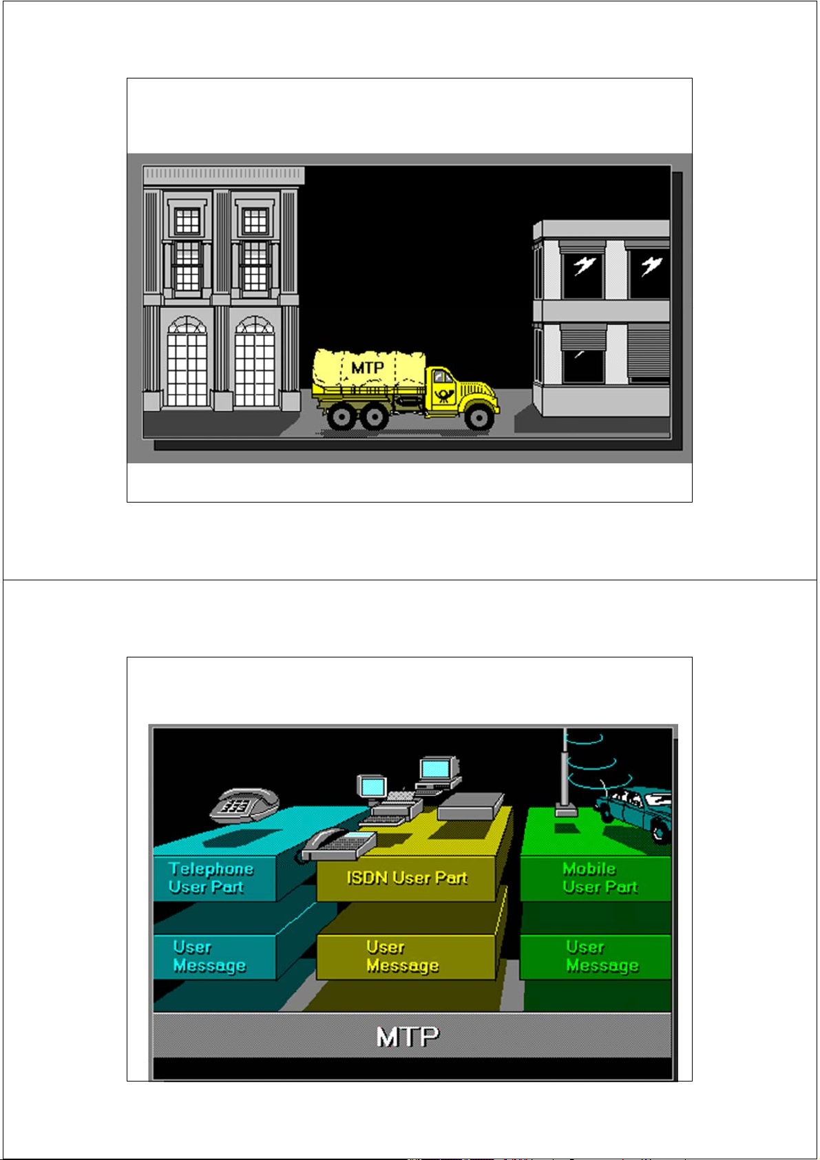
– CDMA2000, W-CDMA and TD-SCDMA 70 2/17/2014 Multi-Access Radio Techniques 71 2/17/2014 72 2/17/2014
Trường Đại học Bách Khoa Hà Nội
Khoa Điện tử Viễn thông Thông tin di động Mobile Communications
TS. Đỗ Trọng Tuấn
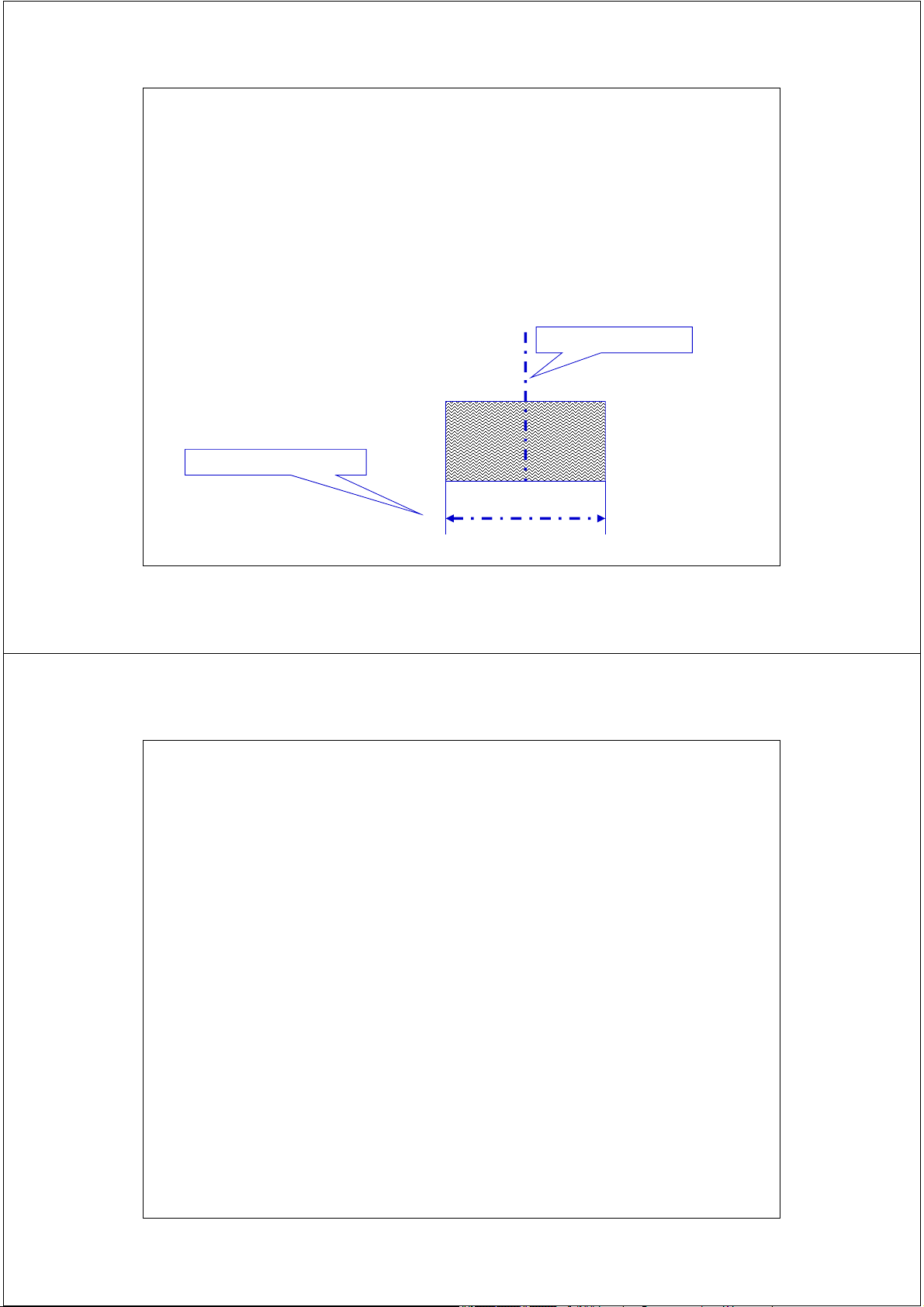
Bộ môn Kỹ thuật thông tin Hà Nội, 8-2010 1 2/17/2014 Truyền sóng trong thông tin di động 2 2/17/2014 Khái niệm kênh vô tuyến Các thuật ngữ tiếng Anh • Mobile Radio Channel • Wireless Channel
• Radio Frequency Channel - RFC Fc: tần số trung tâm
∆f: Độ rộng kênh tần số 3 2/17/2014
Các phương thức truyền tin song công giữa MS và BS • Phân chia theo tần số FDD: Frequency Division Duplex
• Phân chia theo thời gian TDD: Time Division Duplex 4 2/17/2014
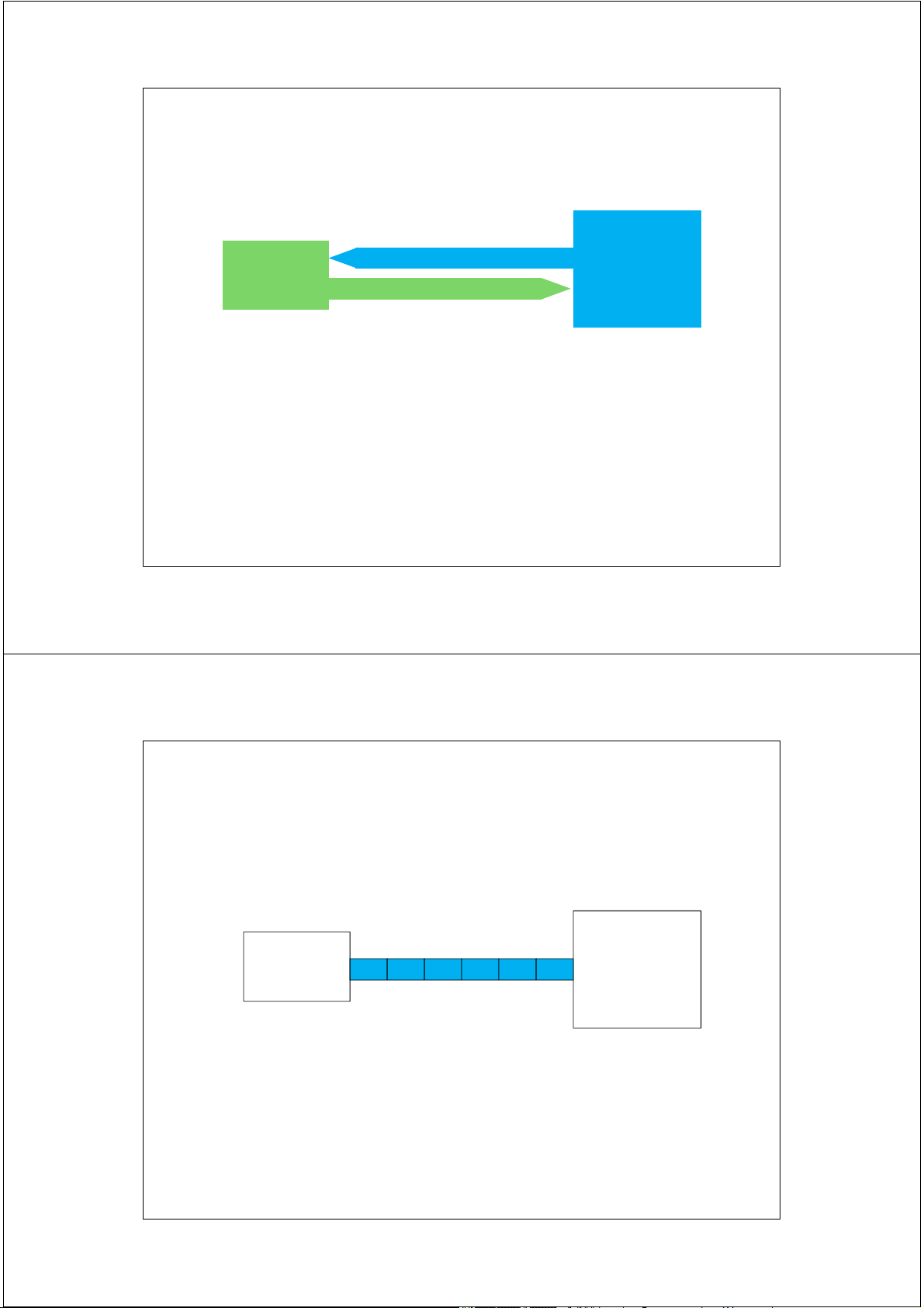
Truyền song công phân chia theo tần số - FDD
• FDD: Frequency Division Duplex Mobile Forward Channel Base Station Station B M Reverse Channel
Hướng xuống: Downlink ~ Hướng thuận:Forward Channel
Hướng lên: Uplink ~ hướng ngược : Reverse Channel
Phương thức FDD sử dụng kênh tần số ở hai băng tần khác
nhau để mang thông tin theo hai hướng. 5 2/17/2014
Truyền song công phân chia theo thời gian - TDD • TDD: Time Division Duplex Mobile Base Station Station M B M B M B B M
Phương thức TDD sử dụng cùng một kênh tần số để mang
thông tin theo hai hướng tại các khe thời gian luân phiên. 6 2/17/2014 Băng tần của hệ thống
• Mỗi hệ thống thông tin di động được cấp
phát một hoặc nhiều băng tần xác định.
• Trong mỗi băng tần, các kênh vô tuyến của
hệ thống sẽ được ấn định.
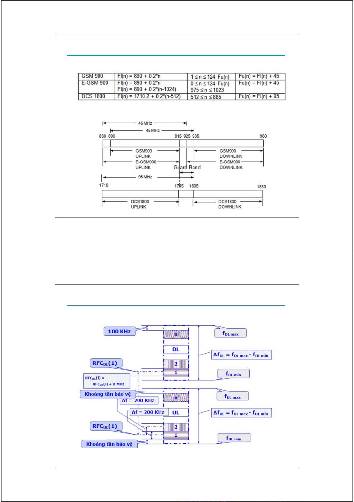
Ví dụ: Băng tần GSM 900 được cấp phát là - UL: 890 MHz – 915 MHz - DL: 935 MHz – 960 MHz
* Hệ thống GSM sử dụng phương thức truyền song công nào ? 7 2/17/2014
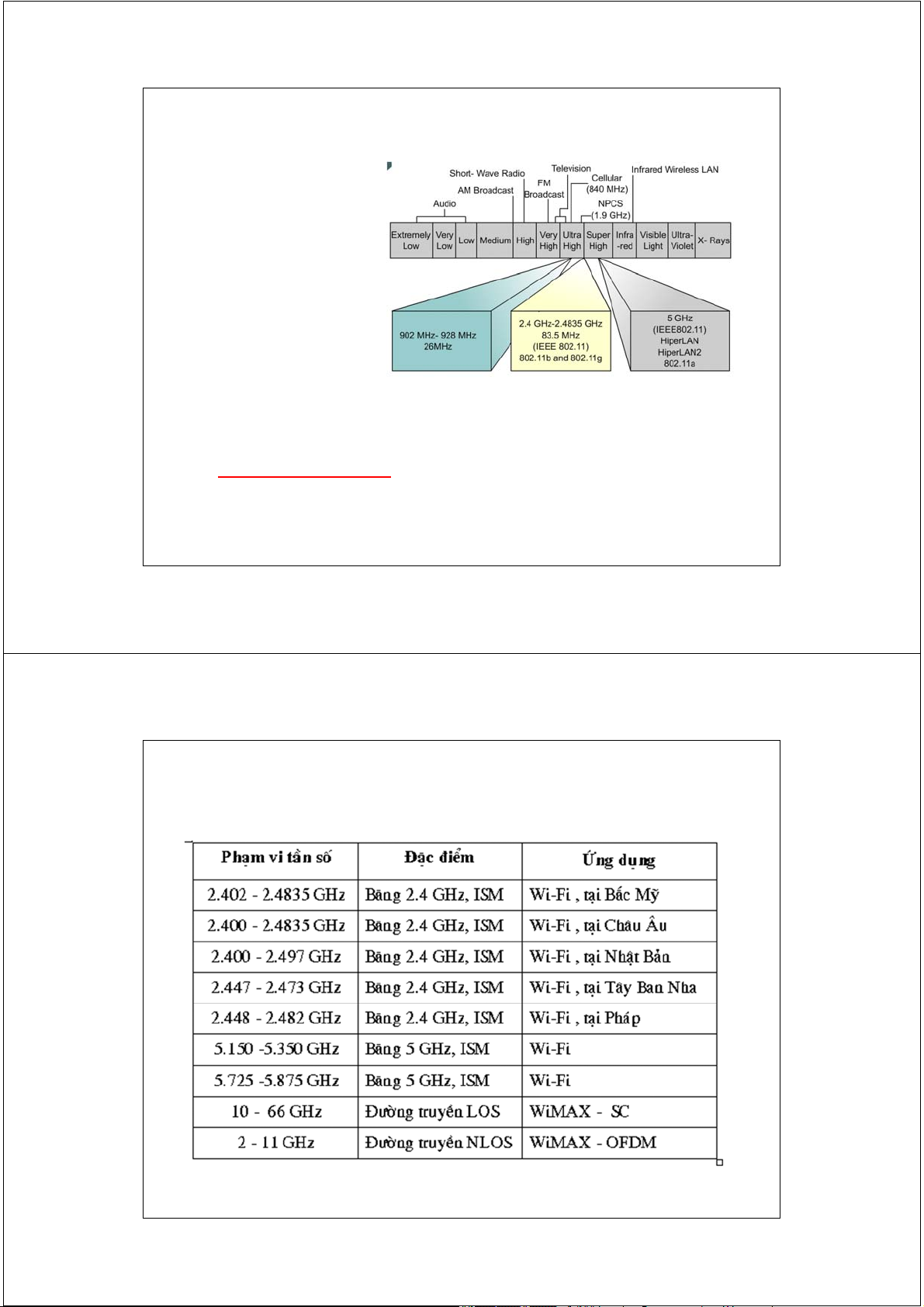
Bước sóng của một số dải tần • GSM 900:
– Tần số ~= 900 Mhz Bước sóng ~= 33.3 cm • DCS 1800 – Tần số ~= 1.8 Ghz Bước sóng ~= 16.7 cm • PCS 1900 – Tần số ~= 1.9 Ghz Bước sóng ~= 15.7 cm • Wi-fi, Bluetooth: – Tần số ~= 2.4Gz Bước sóng ~= 12.5cm 8 2/17/2014
Quy định cấp phát kênh trong hệ thống GSM ARFCN Channels Assignment 9 2/17/2014
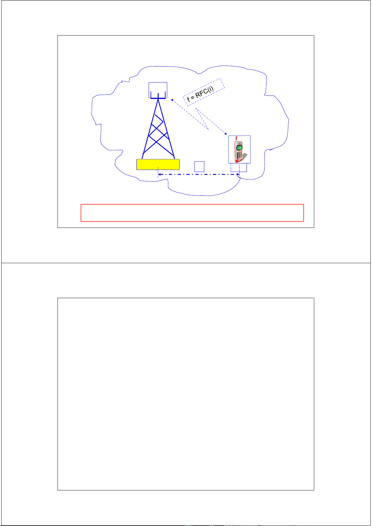
Quy định cấp phát kênh trong hệ thống GSM 10 2/17/2014 Môi trường truyền sóng C A D MS B Transmitter Receiver BTS
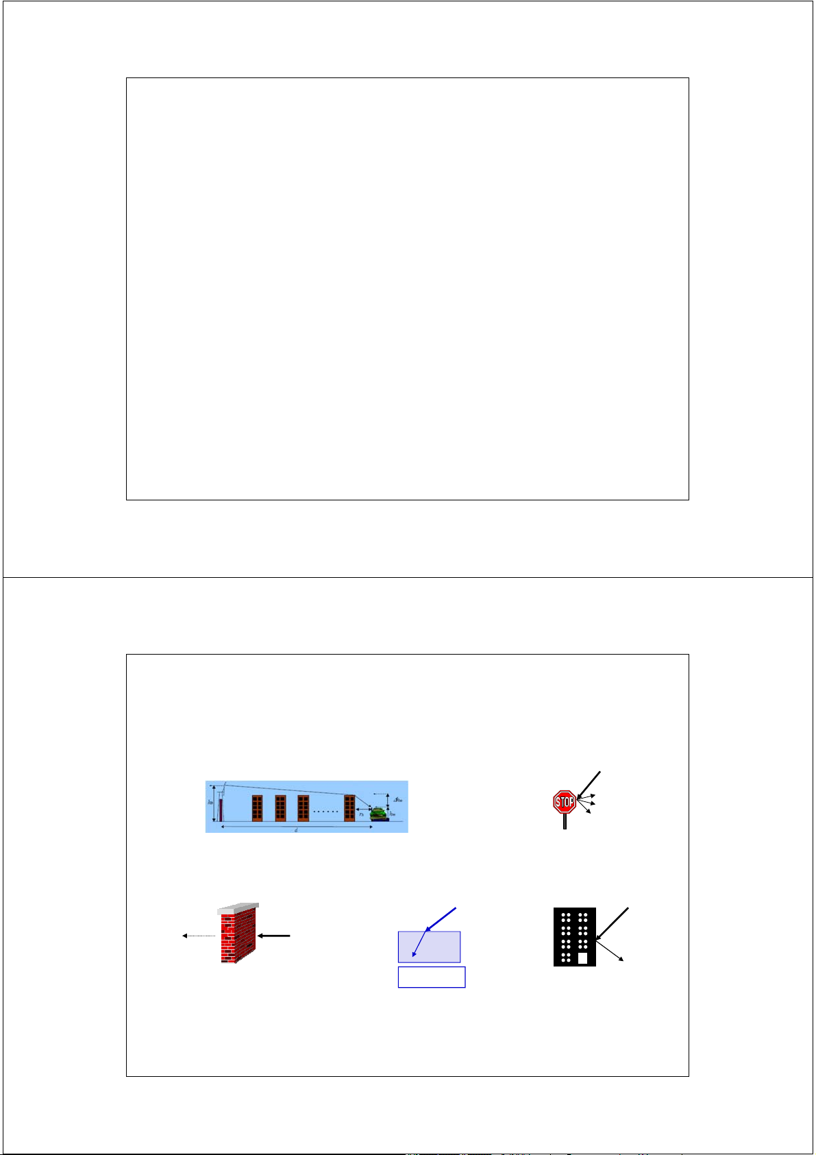
A: truyền thẳng - free space B: phản xạ - reflection C: khúc xạ - diffraction D: tán xạ - scattering
reflection: đối tượng phản xạ có kích thước >> bước sóng
scattering: đối tượng phản xạ có kích thước nhỏ hoặc bề mặt gồ ghề 11 2/17/2014
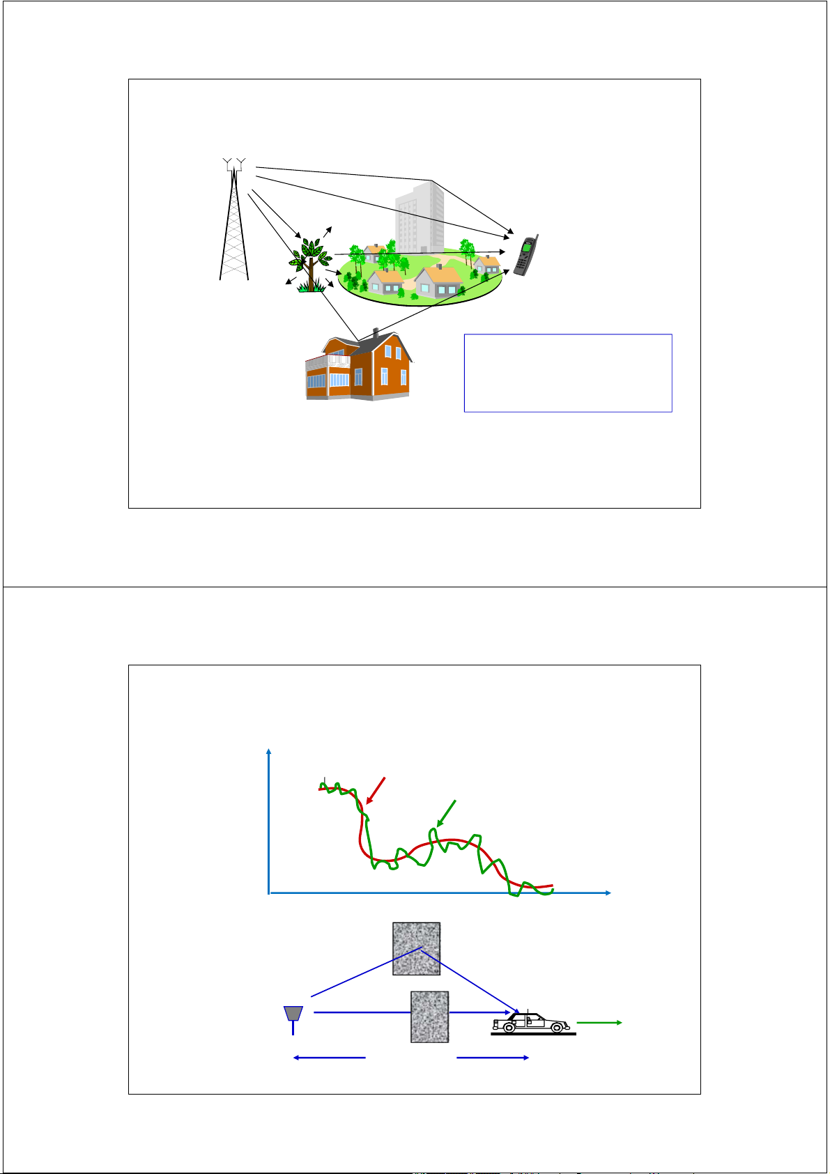
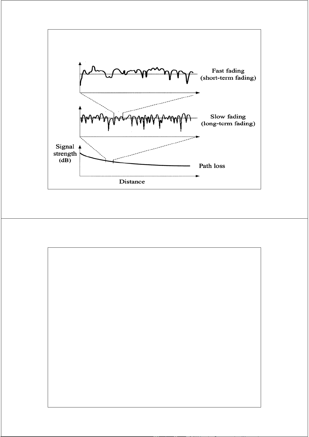
Đặc tính truyền sóng - Propagation Characteristics Pr/Pt Slow Fast Very slow d=vt Pt Pr v d=vt 12 2/17/2014 Pha đinh - Fading 13 2/17/2014 Pha đinh - Fading
Là hiện tượng tín hiệu thay đổi ngẫu nhiên về cường độ
hoặc pha hoặc cả hai tại điểm thu theo thời gian.
Pha đinh xảy ra do sự dịch chuyển tương đối tại một
khoảng cách xác định gây nên sự biến đổi đường truyền
giữa trạm gốc BS và trạm di động MS 14 2/17/2014 Fading
Fading is caused by movement over distance to produce
variations in the overall path between the BS and MS. In a
received signal, the time variation of the amplitude or the
relative phase, or both, of one or more of the frequency
components of the signal is known as fading.
Fading is caused by changes in the characteristics of the propagation path with time 15 2/17/2014
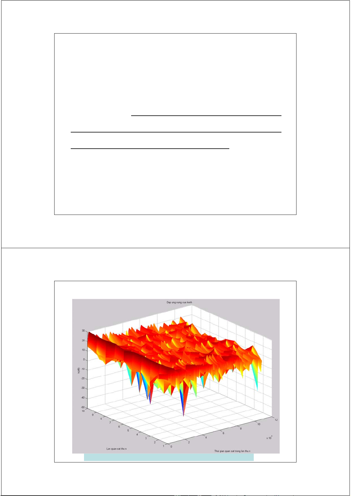
Đáp ứng xung của kênh truyền vô tuyến - CIR CIR : Channel Impulse Response 16 2/17/2014
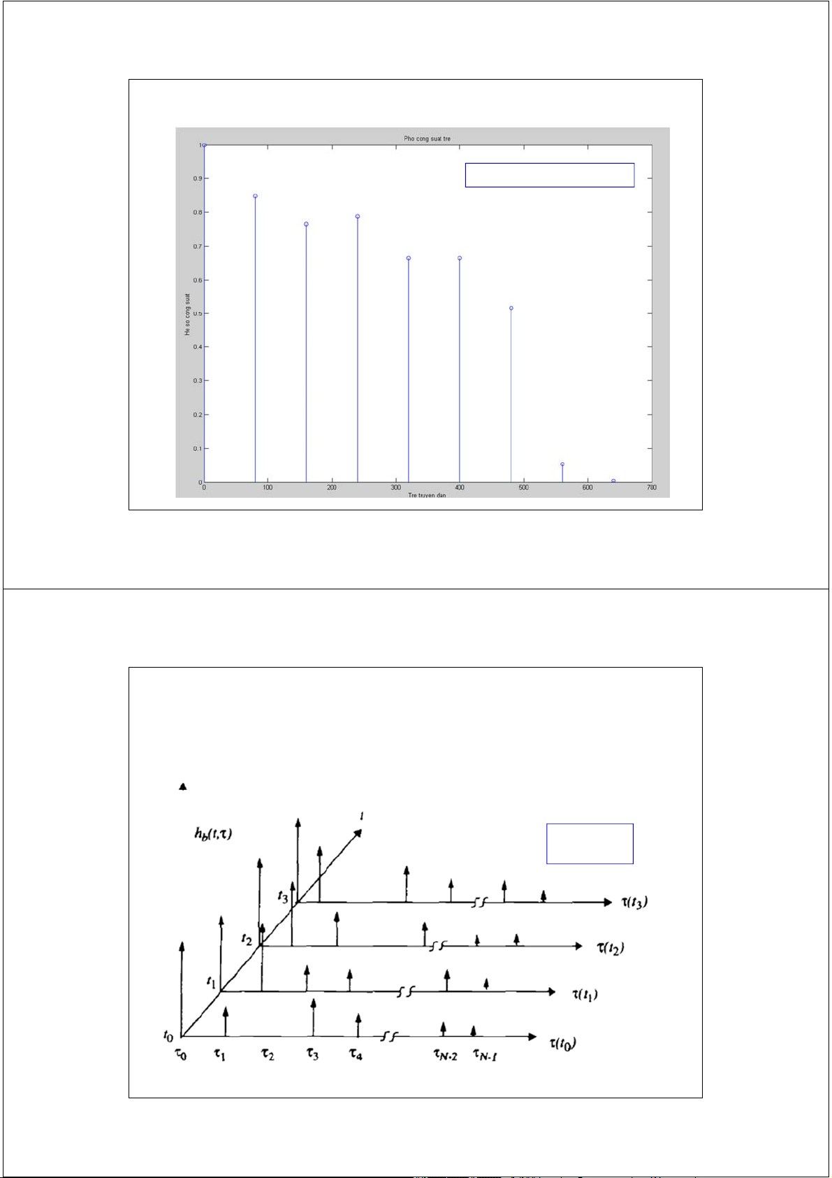
Giản đồ hệ số công suất trễ - truyền đa đường power delay profile 17 2/17/2014
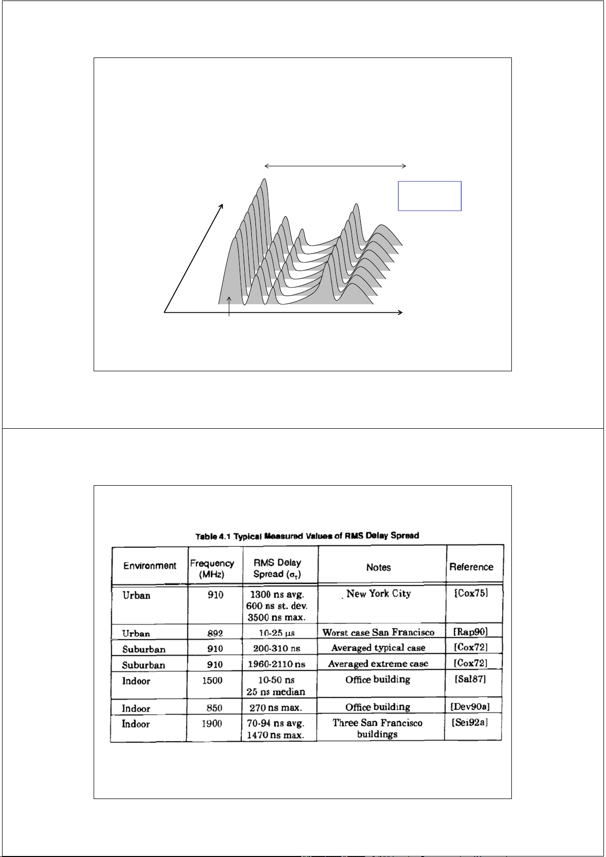
Đáp ứng xung của kênh truyền vô tuyến phụ thuộc theo thời gian Time-variant Channel h( ,t) 18 2/17/2014
Đáp ứng xung của kênh truyền vô tuyến không phụ thuộc theo thời gian Time-variant Channel delay spread Tm h( ) time t zero excess delay delay CIR : Channel Impulse Response 19 2/17/2014 20 2/17/2014
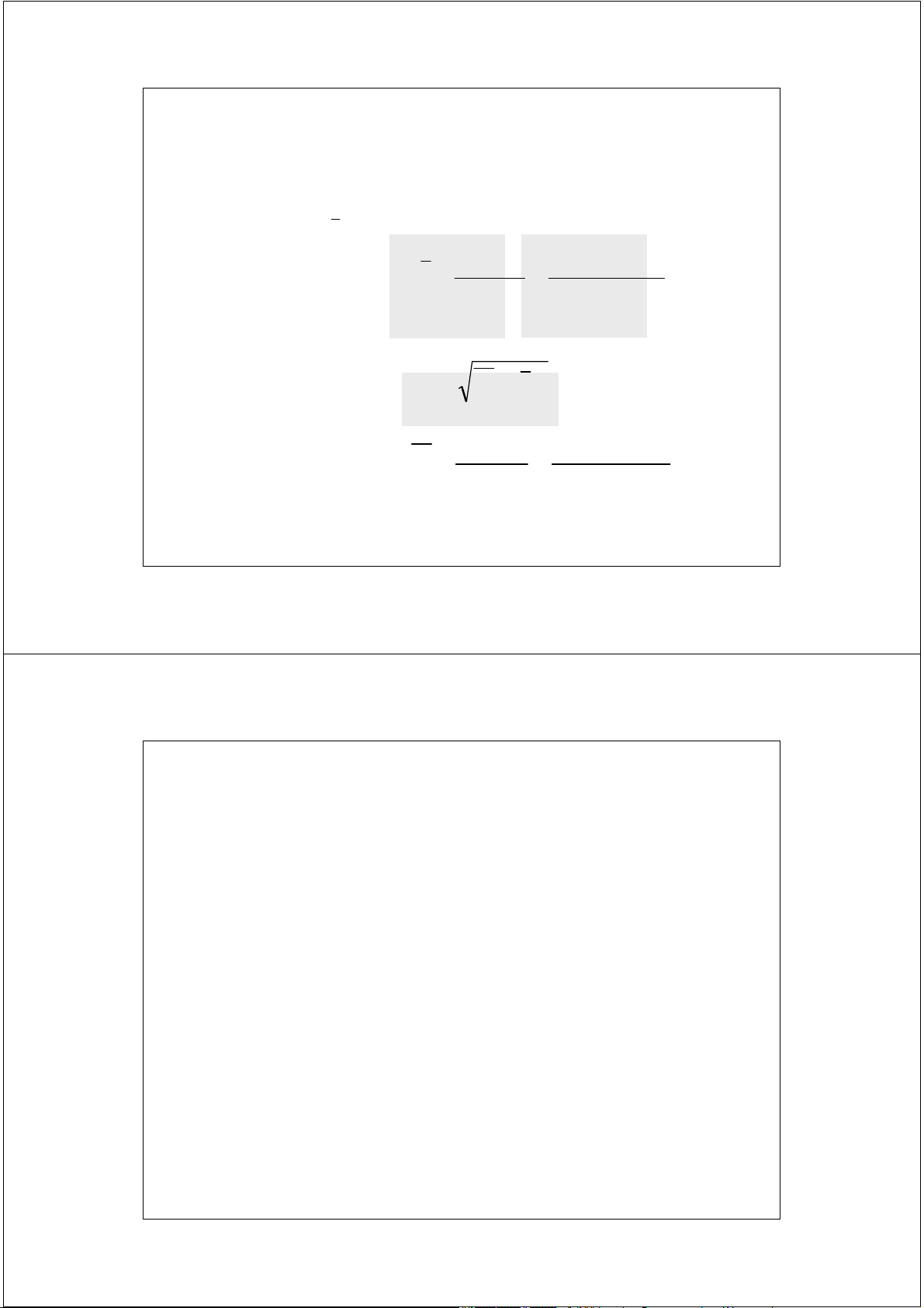
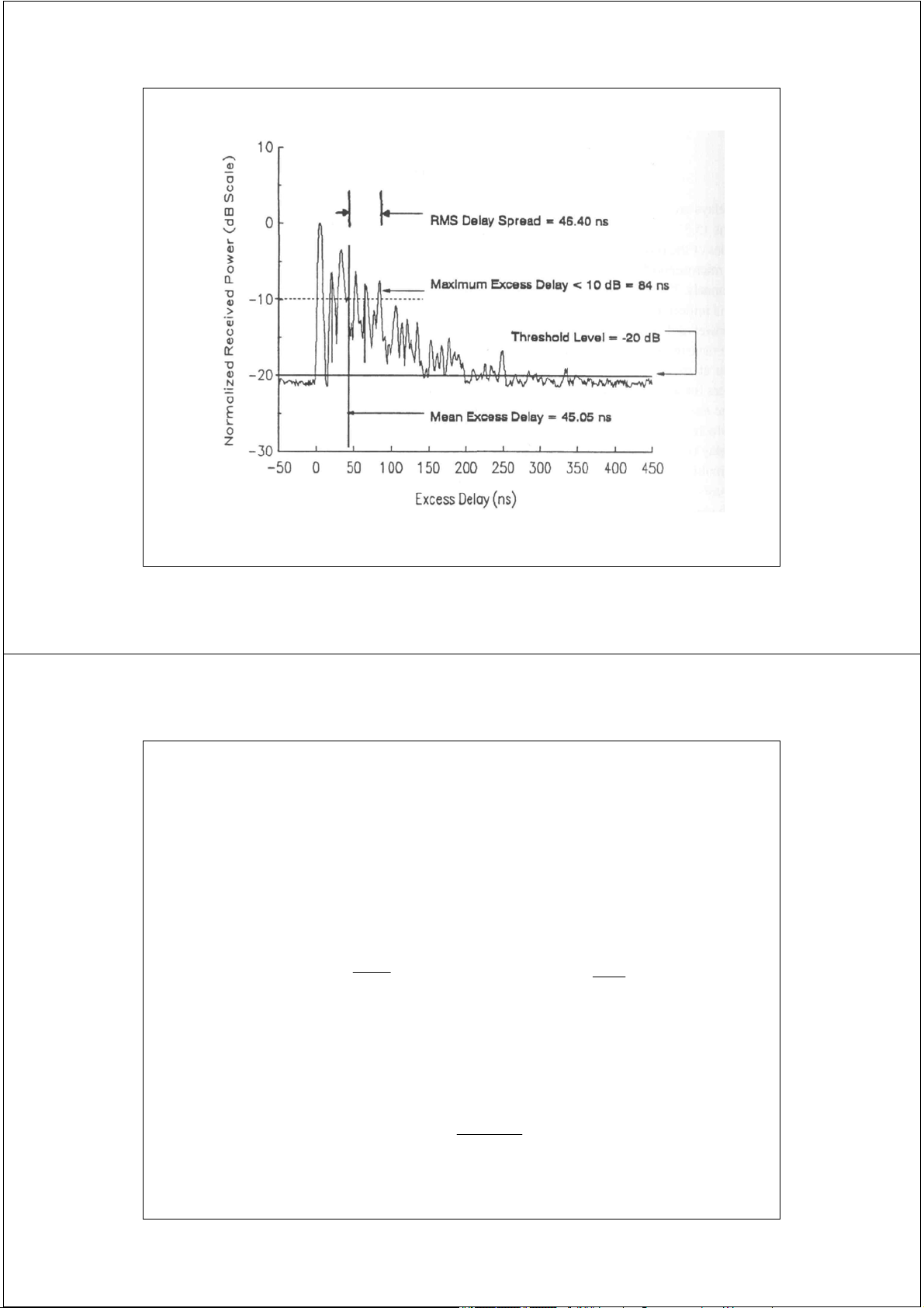
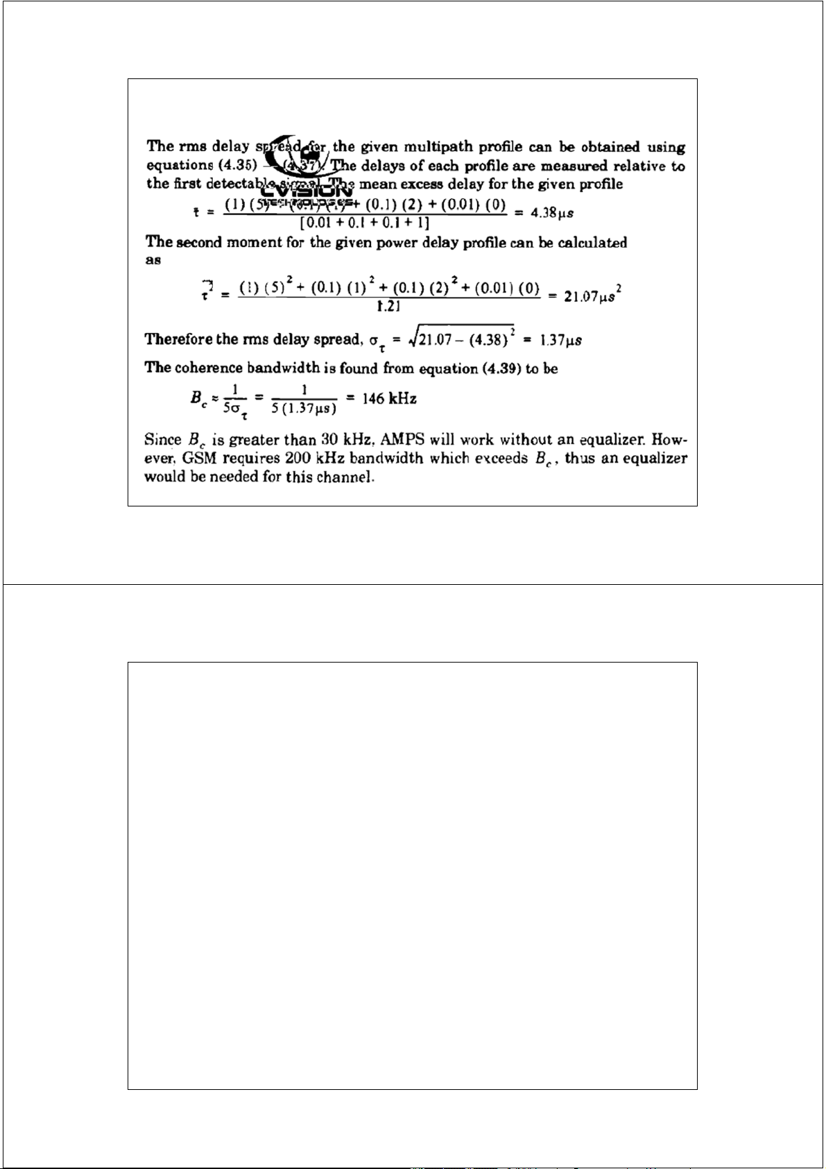
Các tham số trải thời gian Timer Dispersion Parameters
Được xác định từ giản đồ số liệu trễ - công suất ( power delay profile) Mean excess delay( ): a2 P( )( ) k k k k
Trễ tuyến truyền trung bình k k a2 P( ) k k k k
Rms delay spread 2 2
Trải trễ tuyến truyền RMS a2 2 P( )( 2 ) k k k k 2 k k a2 P( ) k k k k 21 2/17/2014
Các tham số trải thời gian Timer Dispersion Parameters
Trễ tuyến truyền tối đa tại mức suy hao X dB x Maximum Excess Delay (X dB)
được định nghĩa là giá trị thời gian trễ tuyến truyền mà sau đó công suất thu x
nhỏ hơn X dB so với công suất của tuyến truyền lớn nhất.
- Tuyến truyền có công suất lớn nhất không nhất thiết phải là truyền truyền đầu tiến đến máy thu.
- Trải trễ tuyến truyền là khoảng thời gian chênh lệch giữa trễ tuyến truyền x
và trễ tuyến truyền đầu tiên 0 - Excess Delay Spread = x 0 22 2/17/2014 23 2/17/2014 Băng thông tương hỗ Bc
và thời đoạn tương hỗ Tc
1. Băng thông tương hỗ - Coherence Bandwidth
- Là bề rộng độ ổn định về mặt tần số của kênh vô tuyến 1 1 B ( f ) (Hz) Hoặc B c c C max 5
2. Thời đoạn tương hỗ - Coherence Duration -
Là bề rộng độ ổn định về mặt thời gian của kênh vô tuyến 1 T ( t ) (s) c c 2 fD,max 24 2/17/2014
Mối quan hệ giữa băng thông tương hỗ Bc
và băng thông tín hiệu truyền Bs
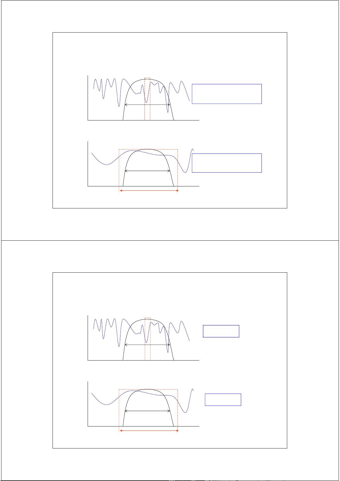
Fading chọn lọc tần số - Freq. Selective Fading Tx BW >> Channel BW B B s s >> Bc ectral density Sp B Freq. c
Fading không chọn lọc tần số - Freq. Flat Fading Tx BW << Channel BW Bs Bs << Bc Spectral density Freq. Coherent BW, Bs 25 2/17/2014
Mối quan hệ giữa thời đoạn tương hỗ Tc
và độ rộng bít tín hiệu Ts
Fading biến đổi nhanh - Fast Fading litude T am s >> Tc Ts T Time c
Fading biến đổi chậm - Slow Fading T amplitude s << Tc Ts Time Coherent Duration, Ts 26 2/17/2014
Phân loại fading phạm vi hẹp Kênh băng rộng Small-scale Fading Kênh băng hẹp
(Based on Multipath Tİme Delay Spread) WideBand channel NarrowBand channel Flat Fading
Frequency Selective Fading
1. BW Signal < BW of Channel
1. BW Signal > Bw of Channel
2. Delay Spread < Symbol Period
2. Delay Spread > Symbol Period Small-scale Fading (Based on Doppler Spread) Fast Fading Slow Fading 1. Low Doppler Spread 1. High Doppler Spread
2. Coherence Time > Symbol Period
2. Coherence Time < Symbol Period
3. Channel variations smaller than baseband
3. Channel variations faster than baseband signal variations signal variations 27 2/17/2014 Ví dụ 4.1 28 2/17/2014 Ví dụ 4.1 29 2/17/2014
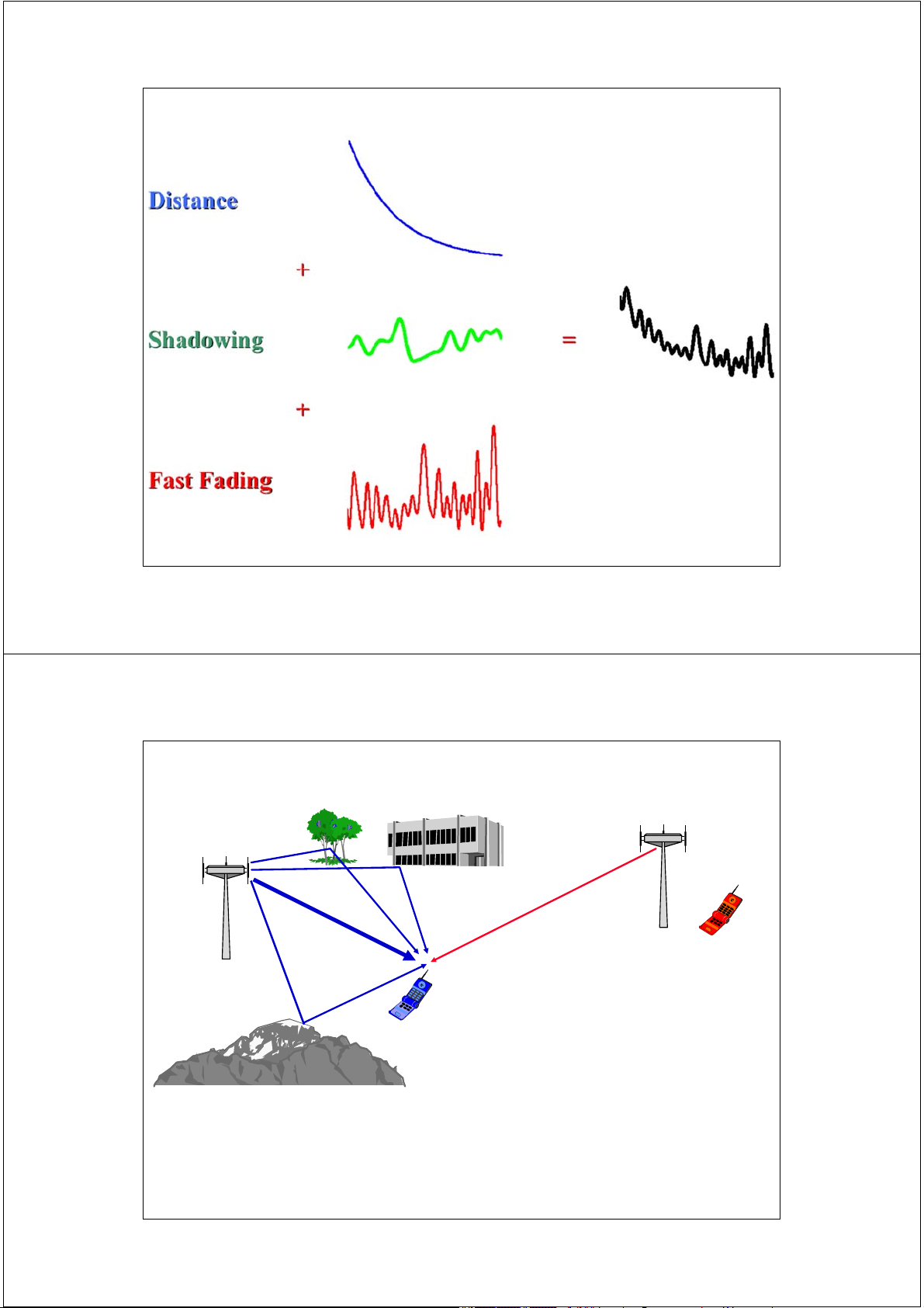
Đặc tính truyền sóng - Propagation Characteristics
• Pha đinh phạm vi rộng ( Large-scale Fading )
– Suy hao đường truyền - Path Loss
– Che khuất - Shadowing (due to obstructions)
• Pha đinh phạm vi hẹp ( Small-scale Fading )
– Pha đinh nhiều đường - Multipath Fading 30 2/17/2014 Pha đinh - Fading
• Pha đinh phạm vi hẹp ( Small-scale Fading )
• Pha đinh nhanh ( Fast Fading) - Pha đinh chậm ( Slow Fading)
gây nên do hiệu ứng Doppler ( frequency dispersion )
• Pha đinh không lựa chọn tần số ( Flat Fading) - Pha đinh lựa chọn
tần số ( Frequency Selective Fading ), gây nên do hiện tượng trễ tín
hiệu ( time dispersion - delay spread ).
• Pha đinh Rayleigh ( không tồn tại đường truyền LOS ) - Pha đinh
Rician ( tín hiệu thu bao hàm cả đường truyền LOS) 31 2/17/2014 Pha đinh phạm vi rộng Các thuật ngữ tiếng Anh * Large-scale Fading * Long-term Fading
• - Cường độ tín hiệu thu trung bình cục bộ giảm dần khi MS di chuyển
ra xa trạm gốc BS gây nên do suy hao đường truyền.
• - Công suất thu trung bình cục bộ được tính toán thông qua việc xác
định mức trung bình tín hiệu đo đạc sau một khoảng cách di chuyển
từ 5λ đến 40λ (GSM: 1,2 m ÷ 12 m).
• - Các mô hình tính toán suy hao đường truyền (large-scale
propagation models) cho phép ước đoán cường độ tín hiệu trung
bình giữa BS và MS tại một khoảng cách xác định. Các mô hình này
có ý nghĩa trong việc tính toán thiết kế và quy hoạch vùng phủ sóng. 32 2/17/2014 Pha đinh phạm vi hẹp Các thuật ngữ tiếng Anh * Small-scale Fading * Short-term Fading
• - Cường độ tín hiệu thu dao động nhanh khi MS dịch chuyển một khoảng cách nhỏ.
• - Nguyên nhân gây pha đinh nhanh là do tín hiệu thu là tổng hợp của
nhiều thành phần đền từ nhiều hướng khác nhau với cường độ, pha
hoặc tần số khác nhau, ngẫu nhiên theo thời gian.
• - Với pha đinh nhanh, công suất tín hiệu thu có thể biến thiên từ 30
dB đến 40 dB khi MS dịch chuyển một khoảng λ/n (a fraction of the wavelength). 33 2/17/2014 Radio Propagation scattering diffraction shadow fading refraction reflection 34 2/17/2014 35 2/17/2014 Wireless Channel Path loss Shadowing Co-channel interference Multipath Propagation • Path loss and shadowing
• Multipath Fading (Self interference) • Noise (SNR) • Other users
• Co-channel interference ( CCI )
• Adjacent-channel interference ( ACI ) 36 2/17/2014 Mô hình không gian tự do Free Space (LOS) Model PBTS BTS d MS
L(dB) = 32,5 + 20 log f (MHz) + 20 log d (km) 37 2/17/2014 Ví dụ 1.
Trong 1 cell, 1 MS đang liên lạc với BTS tại tần số 936 MHz. Hãy cho biết:
a. Suy hao đường truyền khi MS cách BTS 3 km.
b. Giả sử công suất BTS đang phát sóng là 20 W,
hãy cho biết MS có liên lạc được với BTS đó
không khi độ nhạy máy thu là -102 dBm ? 38 2/17/2014
Mô hình truyền dẫn vô tuyến tổng quát
Tổng quát, cường độ tín hiệu nhận được qua môi
trường vô tuyến sẽ tỷ lệ với d-n ( ) n L d d Trong đó:
n : hệ số suy hao đường truyền
n = 2 ~ 8 ( phụ thuộc môi trường truyền dẫn)
n = 4 thường được thiết lập khi nghiên cứu các hệ
thống thông tin di động tế bào. 39 2/17/2014
Mô hình truyền dẫn vô tuyến tổng quát ( ) ( d L d )n d0 ( ) ( ) 10 lg( d L dB L d n ) 0 d0
Trong đó: d0 = khoảng cách tham chiếu - Macro cell -> d0 = 1 km
- Micro cell -> d0 = 100 m hoặc 1m 40 2/17/2014
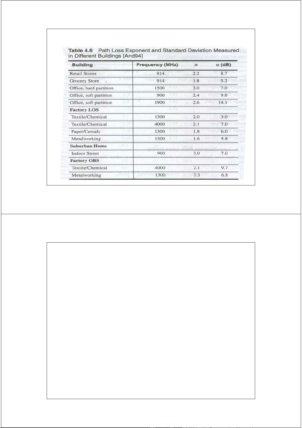
Path Loss Exponent for Different Environments Environment
Path Loss Exponent, n Free space 2
Urban area cellular radio 2.7 to 3.5
Shadowed urban cellular radio 3 to 5
In building line-of-sight 1.6 to 1.8 Obstructed in building 4 to 6 Obstructed in factories 2 to 3 41 2/17/2014
Path Loss Exponent for Different Environments Environment
Path Loss Exponent, n Free space 2
Urban area cellular radio 2.7 to 3.5
Shadowed urban cellular radio 3 to 5
In building line-of-sight 1.6 to 1.8 Obstructed in building 4 to 6 Obstructed in factories 2 to 3 42 2/17/2014 Mô hình hai đường Two ray or PLANE-EARTH Model PBTS LOS hb hm Ground BTS MS d 2 20log( d L ) h h b m 43 2/17/2014 Ví dụ 2
Hãy thực hiện lại ví dụ 1 khi độ cao anten BTS là
30 mét và độ cao trung bình của anten MS là 1,5 mét.
a. Suy hao đường truyền khi MS cách BTS 3 km ?
b. Giả sử công suất BTS đang phát sóng là 20 W, hãy
cho biết MS có liên lạc được với BTS đó không khi
độ nhạy máy thu là -102 dBm ? 44 2/17/2014 Mô hình thống kê Hata PBTS hb hm BTS MS d Nội thành Ngoại ô
Vị trí phú sóng của BTS: Nông thôn 45 2/17/2014 HATA MODEL Tần số làm việc f: 150 – 1500 MHz
Độ cao anten của BS hb: 30 – 200 m
Độ cao anten của MS hm: 1 – 10 m
Khỏang cách giữa MS và BS d: 1 – 20 km
- urban => nội thành - Lp(urb)
- suburban => ngoại ô - Lp(sub)
- open country => nông thôn – Lp(open) 46 2/17/2014 Mô hình HATA Tại vùng đô thị - URBAN
Lp (urb) = 69.55 + 26.16 * log( f ) - 13.82*log( hb ) - a( hm ) +
( 44.9 - 6.55 * log( hb )) * log( d ) [dB]
a(hm):Hệ số hiệu chỉnh độ cao anten MS.
- Diện tích thành phố nhỏ hoặc trung bình:
a(hm)= (1.1*log f - 0.7)hm - (1.56*log f - 0.8) [dB]
- Diện tích thành phố lớn:
a(hm) = 8.29 (log1.54hm)2 - 1.1 [dB]khi 150 <= f <= 200 [MHz]
a(hm) = 3.2 (log11.75hm)2 - 4.97 [dB]
khi 200 < f <= 1500 [MHz]
Tại vùng ngoại ô - SUBURBAN:
Lp(sub) = Lp(urb) - 2 *( log(f/28))2 - 5.4 [dB]
Tại vùng nông thôn - RURAL (OPEN AREAS):
Lp(open) = Lp(urb) - 4.78 *(log(f))2 + 18.33*log(f) - 40.94 [dB] 47 2/17/2014 Ví dụ 3
Giả sử tại một cell ở vùng ngoại ô, trạm gốc BS có độ
cao 50 mét. Một trạm di động MS có độ cao anten trung
bình là 1,5 mét, đang liên lạc với trạm gốc tại tần số 936 MHz. Hãy xác định:
a. Suy hao đường truyền khi MS cách BTS 3 km ?
b. Giả sử công suất BTS đang phát sóng là 20 W, hãy
cho biết MS có liên lạc được với BTS đó không khi độ nhạy máy thu là -102 dBm ? 48 2/17/2014 Mô hình COST 231
Tần số làm việc f : 1500 - 2000 MHz
Độ cao anten trạm gốc hb: 30 - 200 m
Độ cao anten MS trung bình hm: 1 - 10 m
Khoảng cách giữa MS và BS d: 1 - 20 km 49 2/17/2014 COST 231 - HATA MODEL
Lp(urb) = 46.3 + 33.9*log(f) - 13.82*log(hb) - a(hm)
+ [44.9 – 6.55*log(hb)]*log(d) + Cm (dB) với:
a(hm) tương tự như mô hình HATA
Tại thành phố cỡ trung bình hoặc trung tâm ngoại ô Cm = 0 dB
Tại trung tâm đô thị, thủ đô ( metropolitan areas) Cm = 3 dB 50 2/17/2014
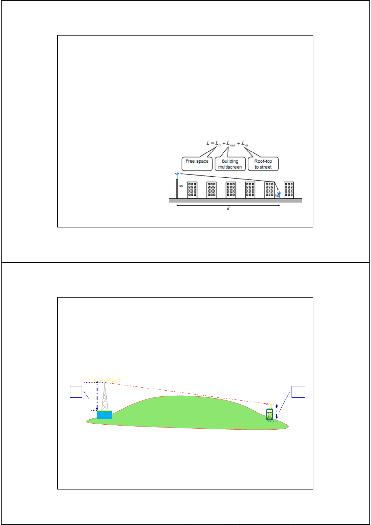
COST-231-Walfisch-lkegami Model
The Okumura-Hata model is not suitable for micro cells or small
macro cells, due to its restrictions on distance (d > 1 km).
The COST 231-Walfish-Ikegami model covers much smaller distances, is
better suited for calculations on small cells and covers the 1800 MHz band as well. Frequency 800 – 2000 MHz Distance 0.02 – 5 km
Mobile station height 1 – 3 m Base station height 4 – 50 m 51 2/17/2014
Khoảng cách chân trời - Radio Horizon D 0.5 0.5 hrz = 4.12 (hb + hm ) (km) hb hm BTS MS
hb = height a.s.l of BTS’s antenna in metres
hm = height a.s.l of MS’s antenna in metres a.s.l = above sea level 52 2/17/2014
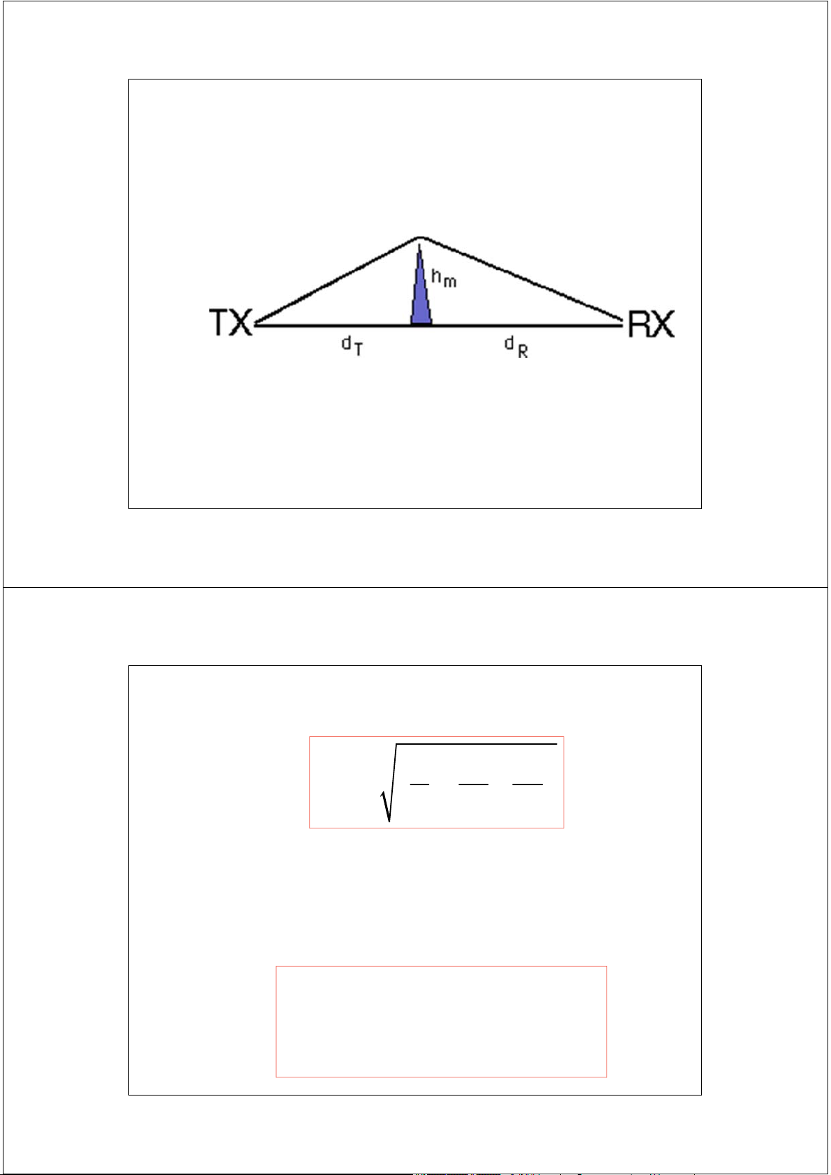
Suy hao do nhiễu xạ - Diffraction loss Mô hình nhiễu xạ đơn
(single) knife edge diffraction 53 2/17/2014
Suy hao do nhiễu xạ - Diffraction loss 2 1 1
h m d d T R Trong đó:
dT và dR là khoảng cách từ điểm phát, thu đến điểm nhiễu xạ
Suy hao do nhiễu xạ được tổng hợp với suy hao không gian tự
do theo đơn vị dB được tính xấp xỉ như sau: 0 0 2 A 6 9 1.27 0 2.4 diff 13 log 2.4 10 54 2/17/2014 Suy hao đường truyền 55 2/17/2014 Suy hao đường truyền
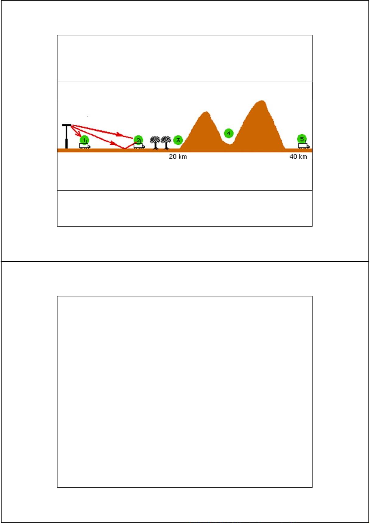
• Mô hìnhd suy hao đường truyền phụ thuộc vào vị trí của anten thu. Ví dụ, 5
vị trí thu trong hình trên được thể hiện như sau:
• Vị trí 1, suy hao không gian tự do cho phép ước đoán chính xác suy hao đường truyền.
• Ví trí 2, tồn tại đường truyền tín hiệu chủ yếu LOS, tuy nhiên tín hiệu phản
xạ từ mặt đất cũng ảnh hưởng đáng kể đến suy hao đường truyền. trong
trường hợp này, mô hình tính toán suy hao 2 đường ( Plane Earth Model )
được sử dụng là thích hợp.
• Vị trí 3, suy hao hai đường cần được hiệu chỉnh do ảnh hưởng của nhiễu xạ
gây nên bởi đám cây nằm giữa đường truyền LOS.
• Ví trí 4, mô hình nhiễu xạ đơn được sử dụng cho phép ước đoán chính xác suy hao đường truyền.
• Ví trí 5, việc ước đoán suy hao đường truyền khá khó khăn và khó tin cậy
do liên quan đến nhiễu xạ nhiều chặng. 56 2/17/2014
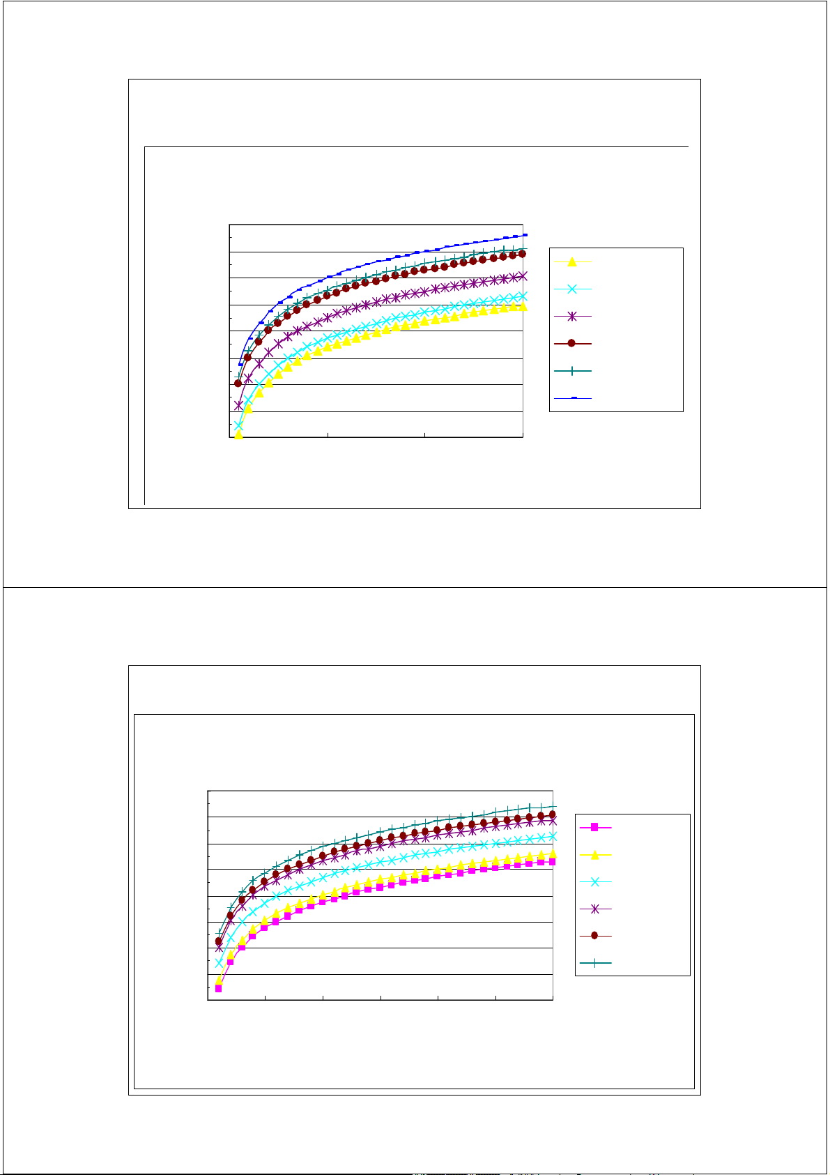
Example of Path Loss (Free-space) Path Loss in Free-space 130 ) 120 fc=150MHz (dB fc=200MHz 110 s Lf fc=400MHz 100 fc=800MHz 90 fc=1000MHz ath Los 80 P fc=1500MHz 70 0 5 10 15 20 25 30 Distance d (km) 57 2/17/2014
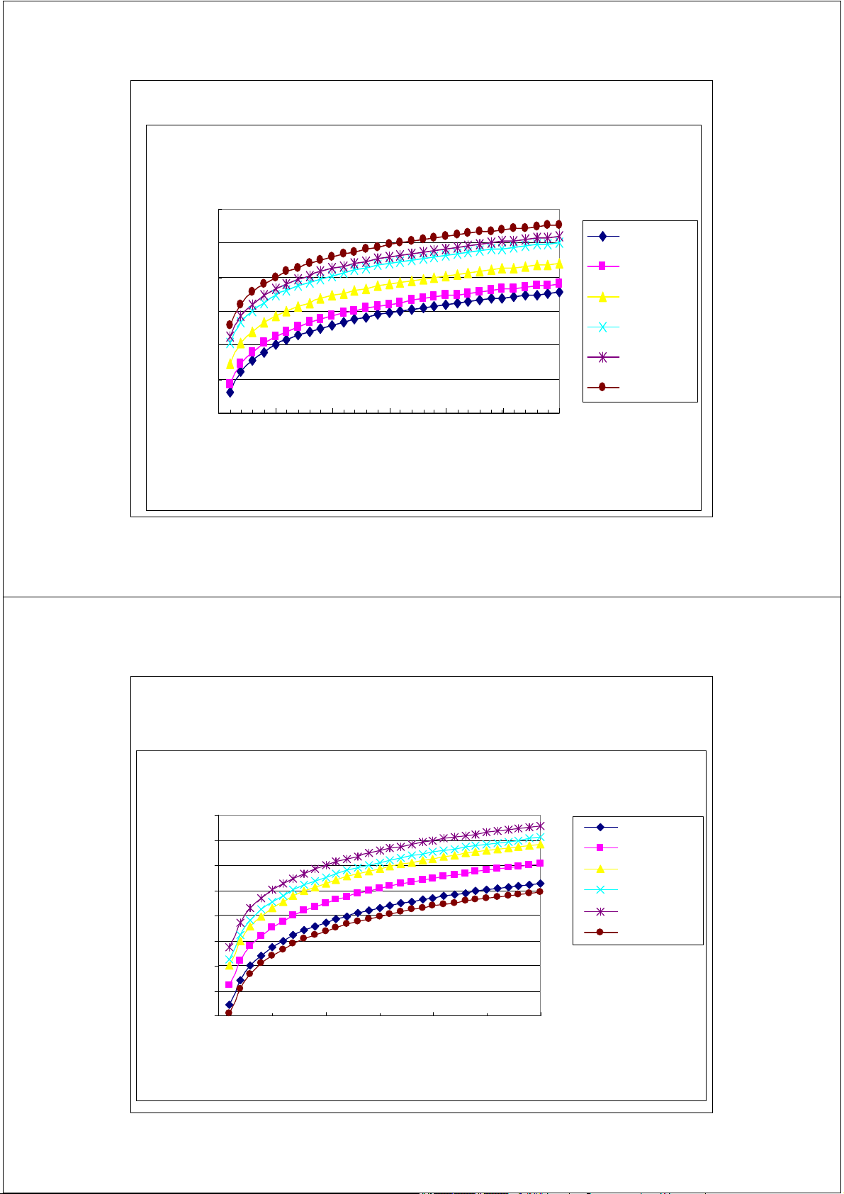
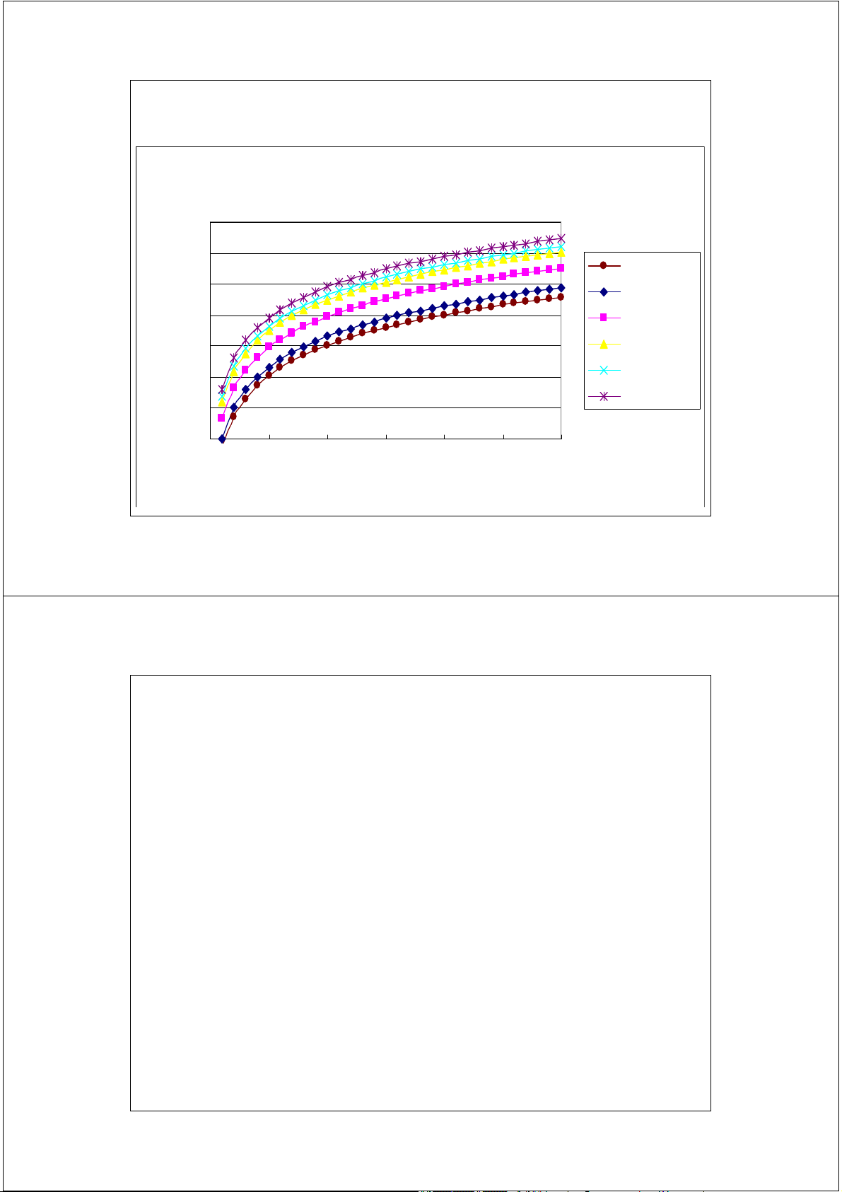
Example of Path Loss (Urban Area: Large City)
Path Loss in Urban Area in Large City 180 fc=200MHz ) 170 fc=400MHz dB 160 fc=800MHz 150 fc=1000MHz s Lpu ( 140 fc=1500MHz fc=150MHz 130 th Los 120 a P 110 100 0 10 20 30 Distance d (km) 58 2/17/2014 Example of Path Loss
(Urban Area: Medium and Small Cities)
Path Loss in Urban Area for Smal & Medium Cities 180 ) 170 fc=150MHz (dB 160 fc=200MHz 150 fc=400MHz s Lpu 140 fc=800MHz 130 fc=1000MHz 120 ath Los P fc=1500MHz 110 100 0 10 20 30 Distance d (km) 59 2/17/2014
Example of Path Loss (Suburban Area) Path Loss in Suburban Area 170 ) 160 B fc=150MHz 150 s (d fc=200MHz p 140 fc=400MHz 130 ss L o fc=800MHz 120 L fc=1000MHz 110 th a fc=1500MHz P 100 90 0 5 10 15 20 25 30 Distance d (km) 60 2/17/2014
Example of Path Loss (Open Area) Path Loss in Open Area 150 ) 140 B fc=150MHz (d 130 fc=200MHz 120 fc=400MHz s Lpo 110 fc=800MHz Los 100 fc=1000MHz th a fc=1500MHz P 90 80 0 5 10 15 20 25 30 Distance d (km) 61 2/17/2014
Mô hình truyền dẫn trong nhà •
Mô hình suy hao đường truyền khoảng cách theo hàm mũ
( Log-Distance Path Loss Model )
Truyền tín hiệu trong môi trường indoor tuân theo quy luật công suất – khoảng cách như sau:
PL(dB) = PL (do) + 10 n log (d/do) + X Trong đó:
- n phụ thuộc vào loại tòa nhà và sự bố trí
- X là biến ngẫu nhiên có biến động chuẩn là [dB].
( biến động chuẩn : standard deviation )
* Tham chiếu n, X theo bảng ở slide kế tiếp. . . 62 2/17/2014
Mô hình truyền dẫn trong nhà 63 2/17/2014 Che khuất - Shadowing Shadowing ~ shadow fading
Tín hiệu nhận được dao động quanh một giá trị trung bình với một
khoảng biến thiên nhất định.
Gây nên do tín hiệu vô tuyến bị chặn bới các tòa nhà (outdoor), hoặc
các bức tường (indoor), hay các vật chắn khác.
Pha đinh chậm - Large time-scale variation 64 2/17/2014 Che khuất - Shadowing
L(d ) L (d ) X [dB] p
( ) ( ) 10 log( d L d L d n ) X [dB] 0 d0
Fading che khuất – biến đổi ngẫu nhiên theo phân bố X [dB]
Gaussian ( phân bố chuẩn ) với giá trị trung bình bằng
không và độ lệch chuẩn là s [dB] Log Normal Shadowing X
is a zero-mean Gaussian (normal) distributed random variable (in sigma
dB) with standard deviation s (also in dB). 65 2/17/2014 Che khuất - Shadowing 66 2/17/2014 Mobile Radio Propagation
[a] Anther Exhibition of Shadowing Effect [b] Marine Environment Showing Shadowing and Multi-path [a] [b] 67 2/17/2014
Trường Đại học Bách Khoa Hà Nội
Khoa Điện tử Viễn thông Thông tin di động Mobile Communications
TS. Đỗ Trọng Tuấn
Bộ môn Kỹ thuật thông tin Hà Nội, 8-2010 1 2/17/2014 CHƯƠNG 2 Hệ thống GSM ξ1. Cấu trúc mạng GSM 2 2/17/2014 GSM
« Groupe Special Mobile »,« Global System for Mobile »
• Bắt đầu nghiên cứu chuẩn hóa vào năm 1982.
• Mục tiêu cho phép thuê bao lưu động ( roaming ) khắp châu Âu.
Chính thức cung cấp dịch vụ năm 1991
• Đa truy nhập TDMA/FDMA (8 thuê bao / 200KHz)
• Băng tần GSM 900 MHz; sau đó mở rộng sang băng tần DCS 1800MHz và PCS 1900 MHz.
Ngày nay, GSM trở thành chuẩn toàn cầu.
• Các giao diện được chuẩn hóa;
• Máy thu GSM ba băng tần có thể lưu động toàn cầu. 3 2/17/2014
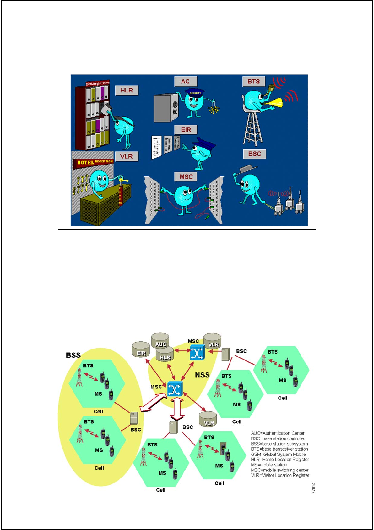
GSM PLMN - Public Land Mobile Network
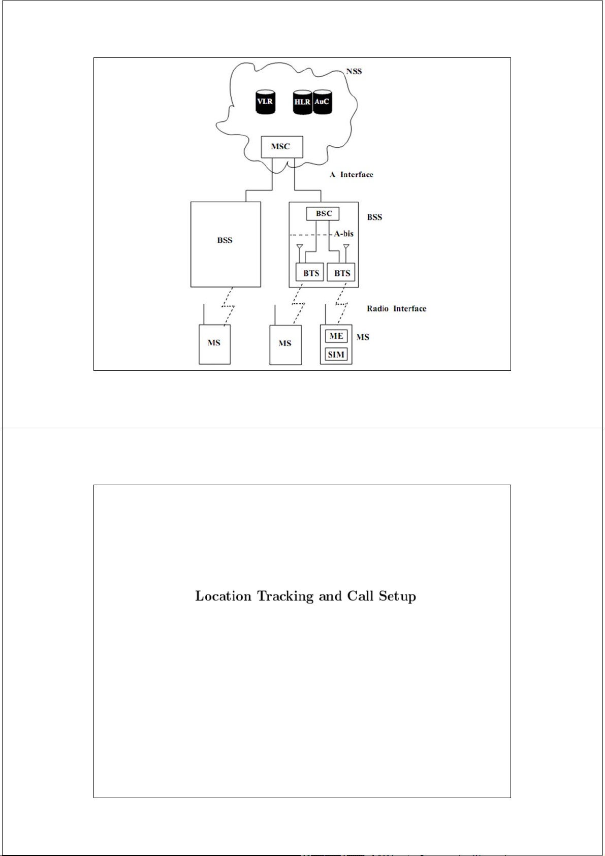
Mạng thông tin di động mặt đất công cộng
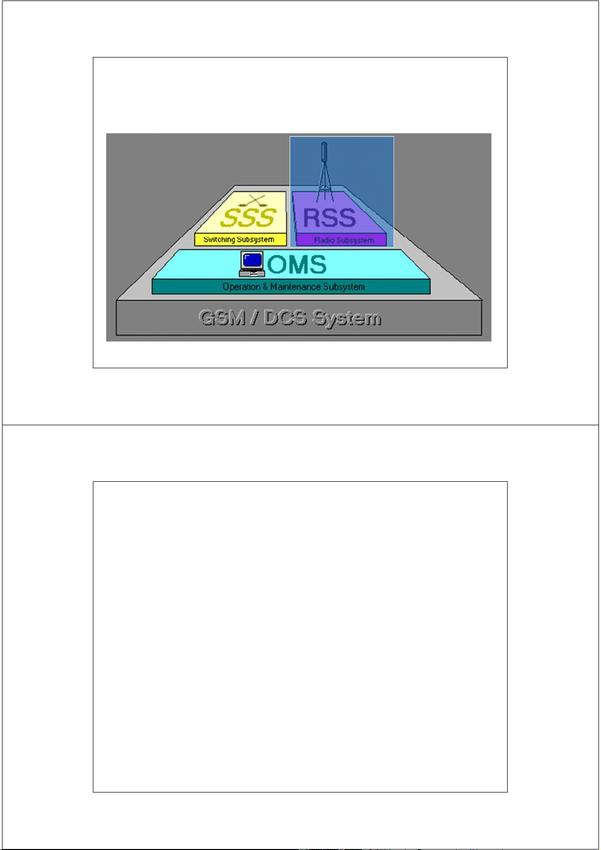
PLMN theo chuẩn GSM được chia thành 3 (4) phân hệ:
• Phân hệ chuyển mạch - NSS
Network Switching Subsystem.
• Phân hệ vô tuyến - RSS = BSS + MS
Radio SubSystem
• Phân hệ vận hành và bảo dưỡng - OMS
Operation and Maintenance Subsystem 4 2/17/2014
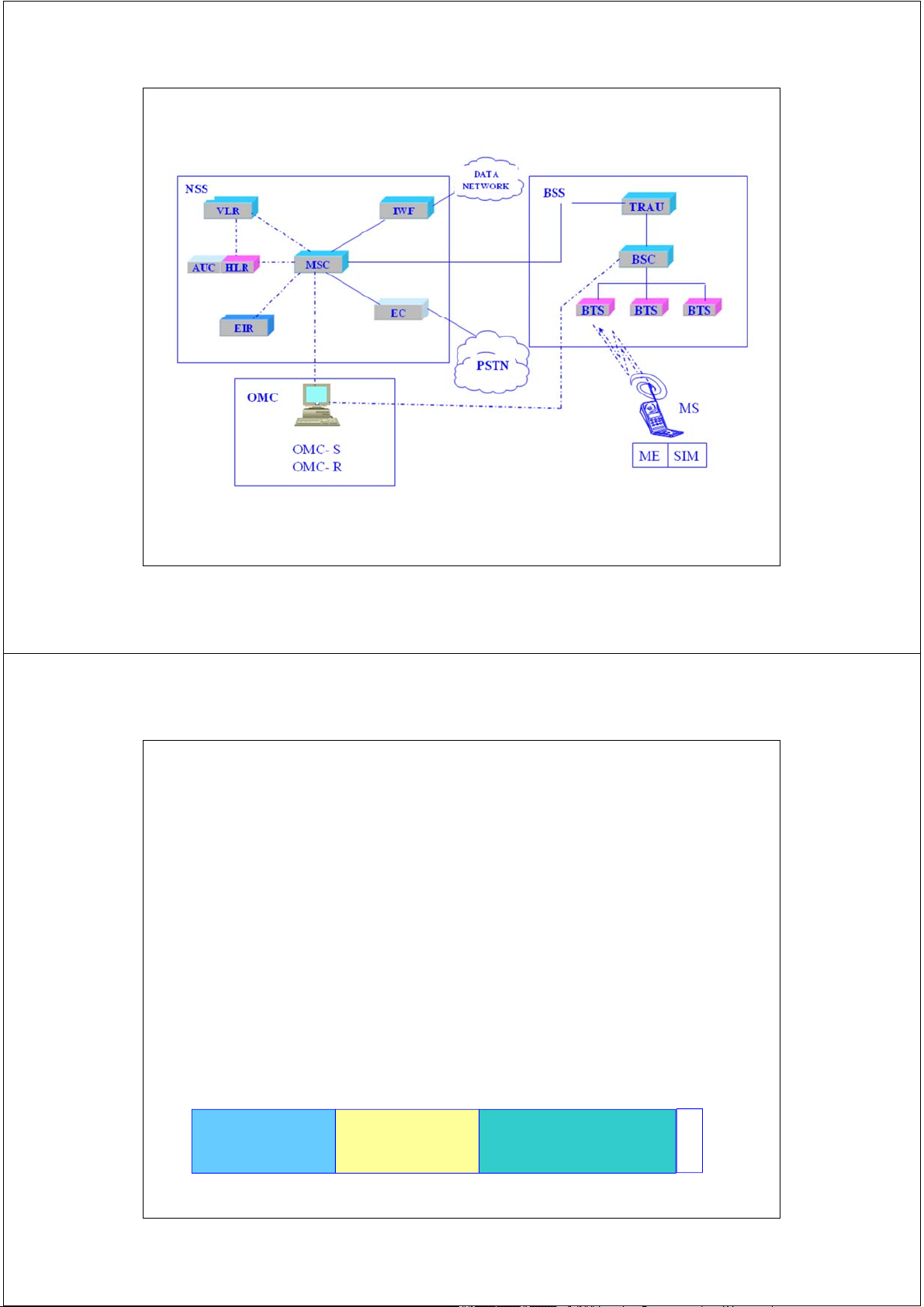
CẤU TRÚC MẠNG PLMN - GSM
IWF: InterWorking Function - Khối tương tác mạng
EC: Echo Canceler - Khối triệt tiếng vọng
Kết nối mang thông tin báo hiệu /điều khiển
Kết nối mang thông tin người sử dụng và báo hiệu 5 2/17/2014
1. Trạm di động MS - Mobile Station
Trạm di động MS = ME + SIM
• ME : Mobile Equipment - thiết bị di động
• SIM: Subscriber Indentity Module
Module nhận dạng thuê bao. ME = hardware + software
ME EMEI = Assigned at the factory 6 digits 2 digits 6 digits 1 digit Type Approval Final Assembly Serial Number Sp Code Code IMEI 6 2/17/2014
1. Trạm di động MS - Mobile Station
SIM: lưu giữ các thông tin nhận thực thuê bao
và mật mã hóa/giải mật mã hóa.
Các thông tin lưu giữ trong SIM:
• Các số nhận dạng IMSI, TMSI • Khóa nhận thực Ki • Khóa mật mã Kc
• Số hiệu nhận dạng vùng định vị LAI
( LAI: Location Area ID)
• Danh sách các tần số lân cận 7 2/17/2014
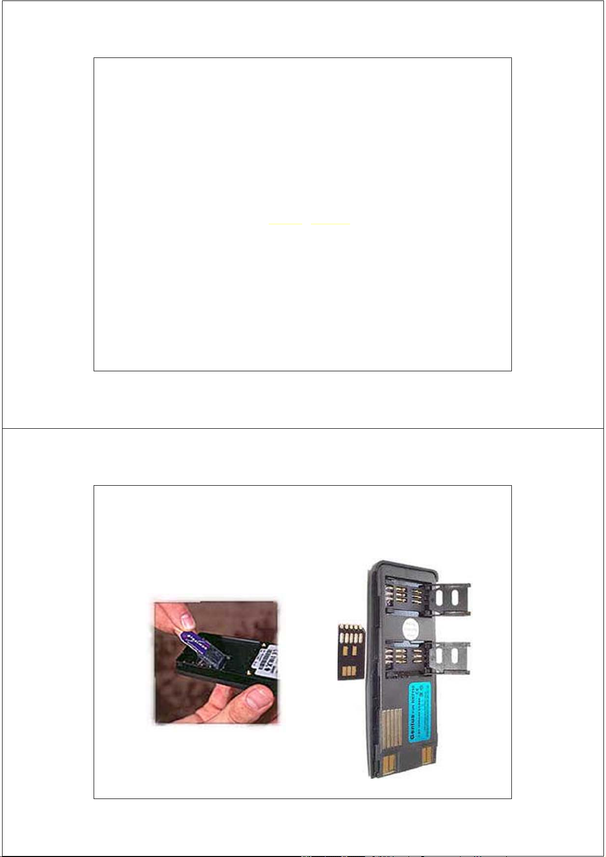
SIM - Subscriber Indentity Module 8 2/17/2014
Số nhận dạng IMSI và MSISDN 3 digits 2 digits Up to 10 digits Mobile Mobile country Mobile subscriber Network Code Code (MCC)
Identification code (MSIC) (MNC)
Số IMSI: International Mobile Subscriber Identity => Số nhận
dạng MS bởi hệ thống, phục vụ báo hiệu và điều khiển. National Country code Subscriber number Destination code (CC) (SN) (NDC)
Số MSISDN: Mobile Station ISDN number => Số danh bạ ,
được nhận dạng bởi thuê bao, phục vụ quá trình thiết lập cuộc gọi. 9 2/17/2014 IMSI and MSISDN MCC MNC MSIC 452 01 xxxxxxx Việt nam Mobiphone 452 02 xxxxxxx Việt nam Vinaphone CC NDC SN 84 90 xxxxxxx Việt nam Mobiphone 84 91 xxxxxxx Việt nam Vinaphone 10 2/17/2014
Số nhận dạng thuê bao tạm thời TMSI
– TMSI được bộ ghi định vị tạm trúc VLR cấp phát cho MS.
– TMSI nhận dạng duy nhất một MS trong vùng điều khiển của 1 VLR.
– TMSI có cấu trúc tối đa 32 bits. Ex
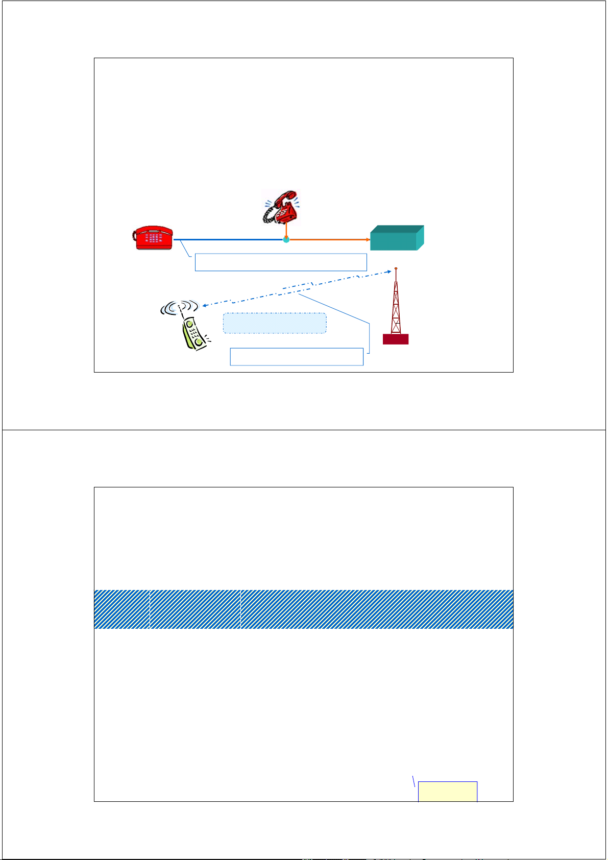
Đường dây thuê bao tương tự IMSI TMSI BTS Giao diện vô tuyến số 11 2/17/2014
Bảng phân loại MS - GSM900 Loại Độ nhạy Pmax Pmin ∆P class Sentivity 1 -104 dBm 20 w Không dùng 2 -104 dBm 8w 39 dBm 3,2 mw 18 3 -104 dBm 5w 37 dBm 3,2 mw 17 4 -102 dBm 2,5w 34 dBm 3,2 mw 15 5 -102dBm 0,8w 29 dBm 3,2 mw 13 5 dBm 12 2/17/2014
Bảng phân loại MS – DCS1800 Loại Độ nhạy Pmax Pmin ∆P class Sentivity 1 -100 dBm 1 w 30 dBm 1 mw 16 2 -100 dBm 0,25 w24 dBm 1 mw 13 3 -102 dBm 4 w 36 dBm 1 mw 19 0 dBm 13 2/17/2014
Số bước điều khiển công suất
Công suất phát của MS:P = Pmin ÷ Pmax Pmin = 3,2 W 5 dBm
Loại MS => Pmax = 0,8 ÷ 8 w
Giá trị bước điều khiển công suất: ∆P = 2 dBm
Tại bước điều khiển công suất i, ta có:
Pt MS = Pmin + ∆P*i = 5 dBm + 2*i trong đó: i = 0 ÷ n-1
n = tổng số mức điều khiển công suất
ví dụ: MS loại 2: Pmax = 39 dBm ? => n = 18 ? 14 2/17/2014
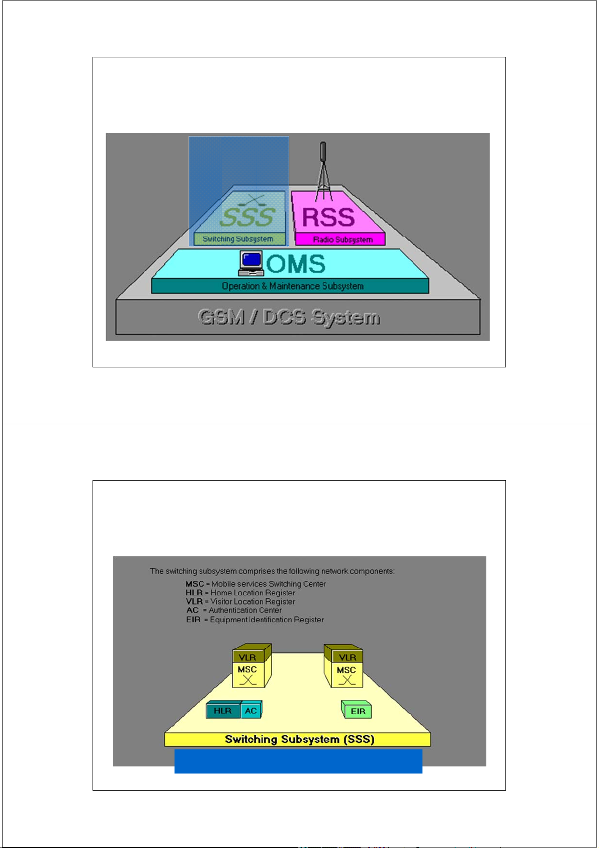
2. Các phân hệ của mạng GSM/DCS 15 2/17/2014
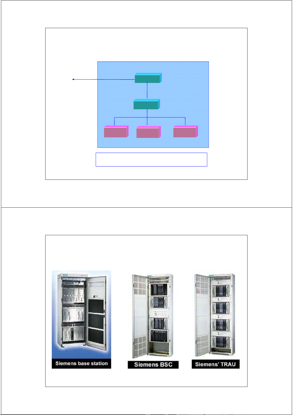
2.1 Phân hệ trạm gốc BSS
BSS: Base Station Subsystem BSS = TRAU + BSC + BTS
• TRAU ( XCDR ): Bộ chuyển đổi mã và phối hợp tốc độ.
• BSC: Bộ điều khiển trạm gốc.
• BTS: trạm thu phát gốc.
BSS kết nối với NSS qua luồng PCM cơ sở 2 Mbps. 16 2/17/2014 BSS’s components BSS MSC trau bsc bts bts bts BSS = TRAU + BSC + BTS 17 2/17/2014 BSS’s components 18 2/17/2014
Trạm thu phát gốc BTS
BTS: Base Tranceiver Station
Trạm thu phát gốc BTS thực hiện các chức năng sau:
• Thu phát vô tuyến (Radio Carrier Tx and Rx)
• Ánh xạ kênh logic vào kênh vật lý
( Logical to physical Ch Mapping )
• Mã hóa/giải mã hóa (Coding/Decoding)
• Mật mã hóa/giải mật mã hóa(Ciphering/Deciphering)
• Điều chế / giải điều chế (Modulating/ Demodulating) 19 2/17/2014
Bảng phân loại BTS - GSM900 Loại - class Pmax (w) Pmax (dBm) 1 320 55 2 160 52 3 80 49 4 40 46 5 20 43 6 10 40 7 5 37 8 2,5 34 20 2/17/2014
Bảng phân loại BTS - DCS1800 Loại - class Pmax (w) Pmax (dBm) 1 20 43 2 10 40 3 5 37 4 2,5 34 21 2/17/2014
Bộ điều khiển trạm gốc BSC
BSC: Base Station Controller
Bộ điều khiển trạm gốc BSC thực hịên các chức năng sau:
• Điều khiển một số trạm BTS: xử lý các bản tin báo
hiệu, điều khiển,vận hành & bảo dưỡng đi/đến BTS. • Khởi tạo kết nối.
• Điều khiển chuyển giao:Intra & Inter BTS HO
• Kết nối đến MSC, BTS và OMC. 22 2/17/2014 Cấu hình BSS 5 2 BTS BTS BTS 1 BTS 4 BSC 3 BTS 6 BTS 7
* Vị trí của BTS so với BSC: BTS
BTS đặt gần: co-located BTS:
* Cấu hình kết nối các BTS:
BTS ở xa: remote BTS: ÷ Hình sao: star - ,,
Hình chuỗi: chain - ,,,
Mạch vòng: loop - ,, ,, ,, 23 2/17/2014
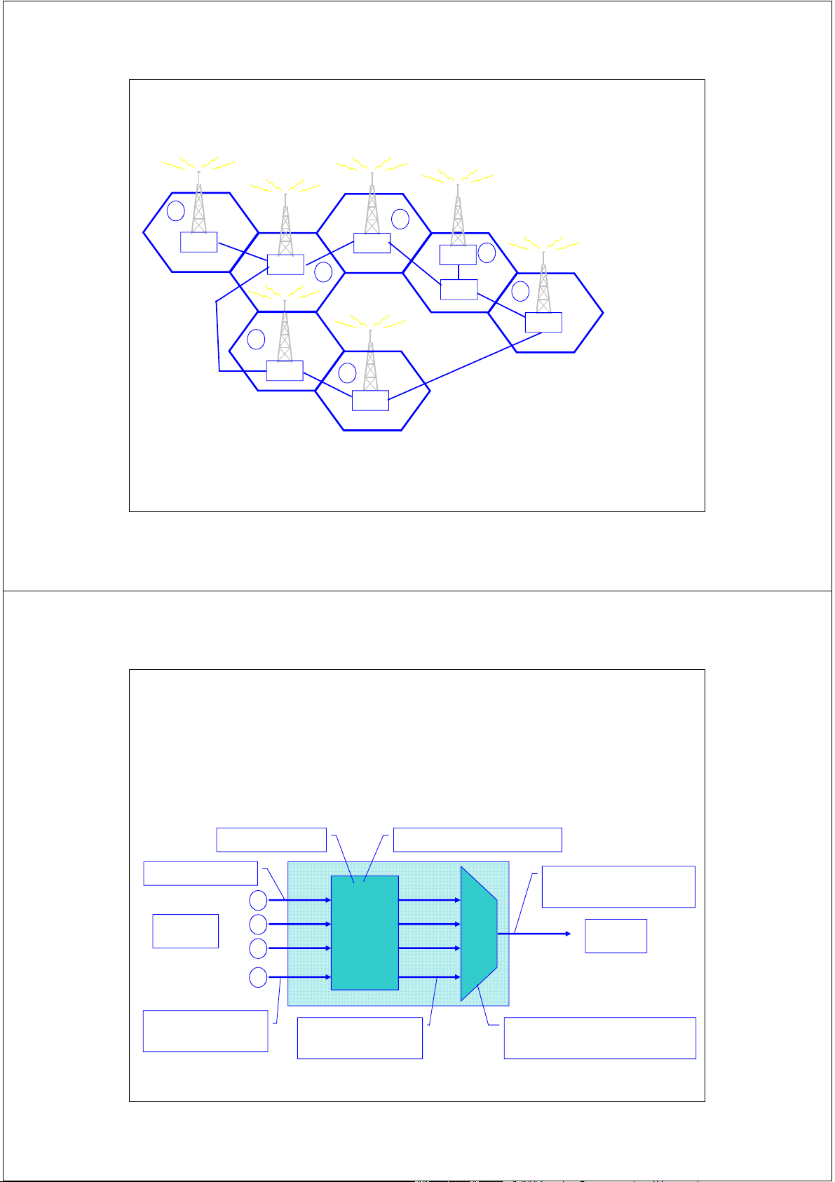
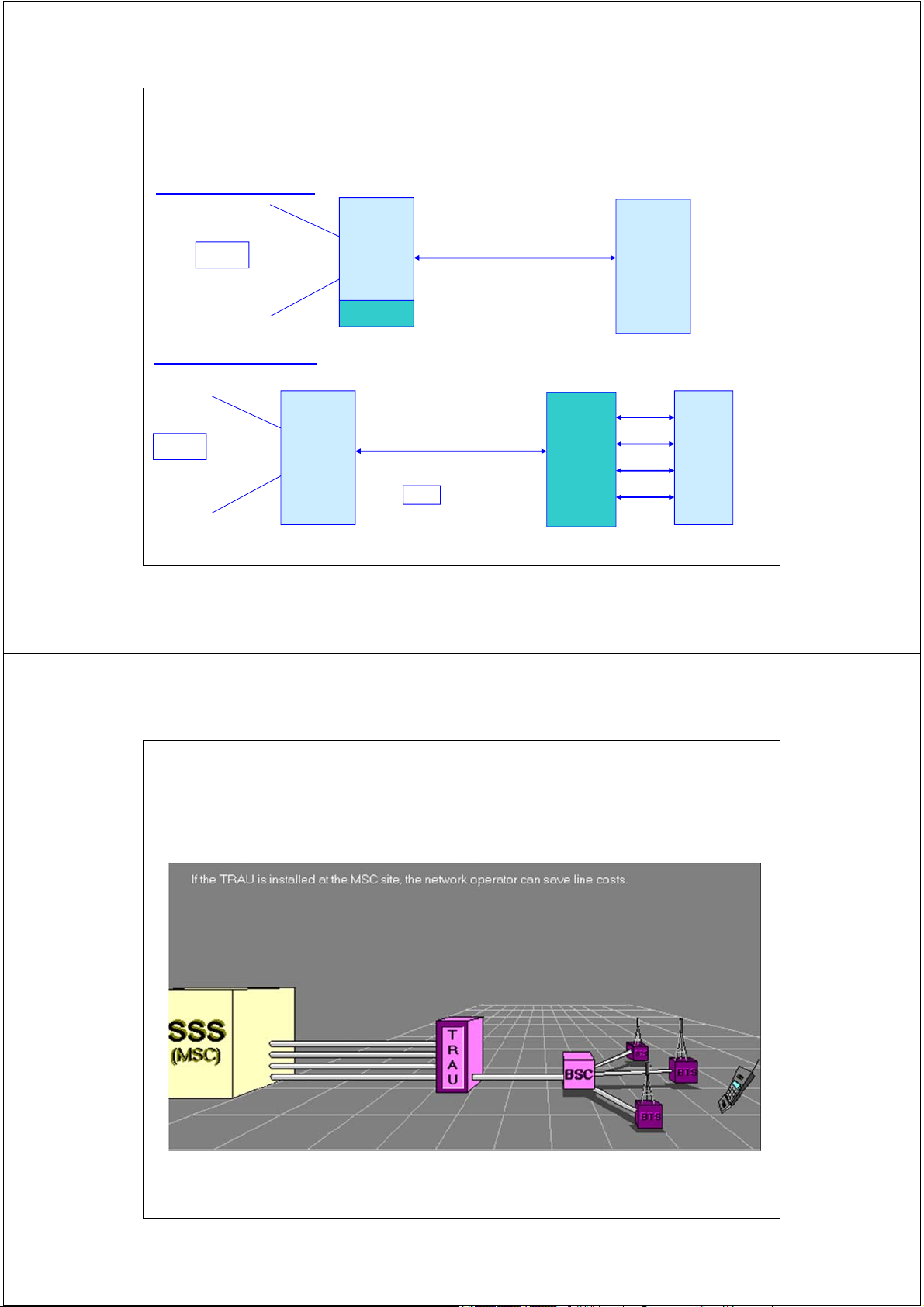
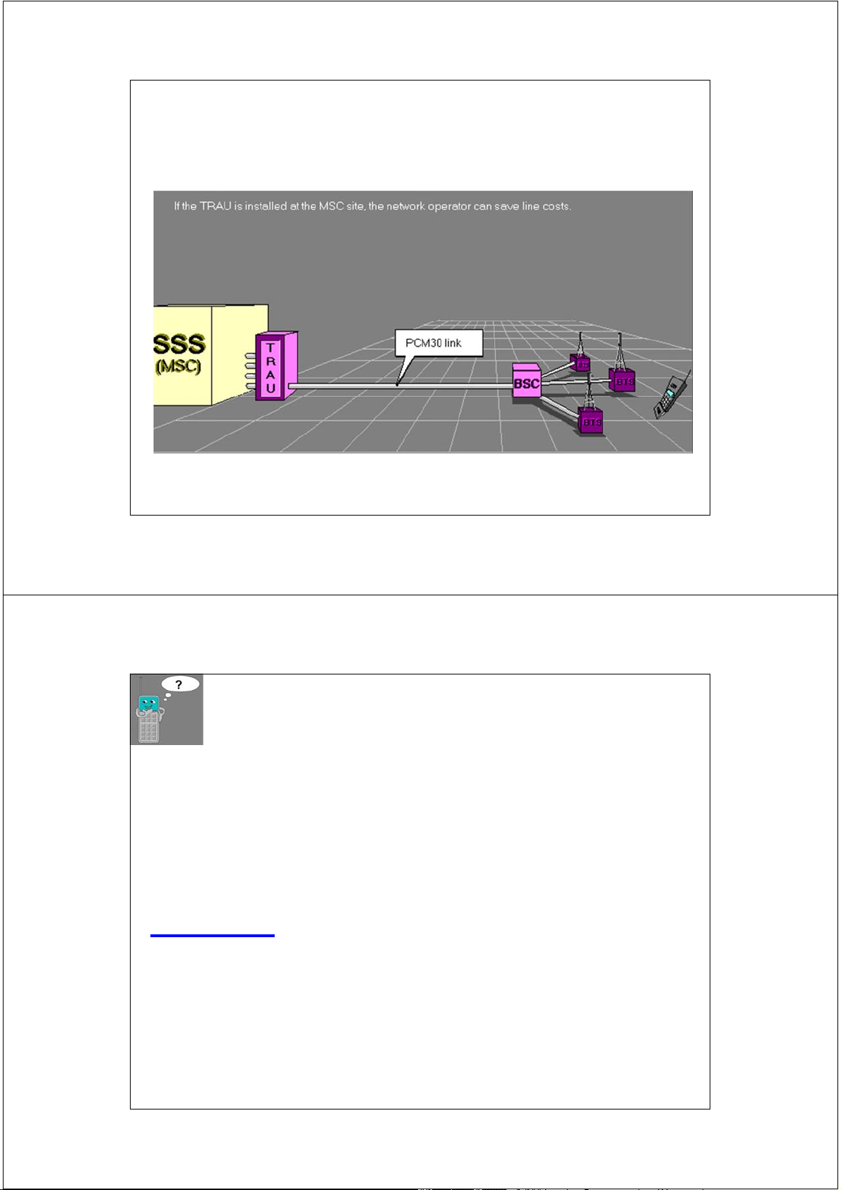
Bộ chuyển đổi mã và phối hợp tốc độ TRAU
TRAU: Transcoding and Rate Adaption Unit
hoặc XCDR : TransCoDeR LPC: 13 Kpbs + header: 3 Kpbs PCM: 64 Kpbs 1 TS (64kpbs) 4 kênh (16kpbs) 1 chuyển MSC 2 đổi BSC 3 MUX mã 4 1 TS 1 kênh Tốc độ 1 kênh Ghép kênh: thoại: 64 kbps thoại: 16 Kpbs 4*(3+13) = 64 Kpbs 24 2/17/2014
Vị trí của TRAU (XCDR) TRAU đặt tại BSC: N x 2Mbps BSC BTS MSC Mỗi luồng E1 =
2Mbps 30 kênh TRAU thoại (64kpbs) TRAU đặt tại MSC: N x 2Mbps BTS BSC TRAU MSC 1 luồng E1 = 2Mbps 120 kênh thoại (16kpbs) 25 2/17/2014
Các thành phần của mạng GSM 26 2/17/2014
Các thành phần của mạng GSM 27 2/17/2014 Ví dụ 1.
1 BTS loại 5 phủ sóng tại vùng ngoại ô của mạng
GSM900, 1 trạm di động loại 2 được cấp phát kênh tần số ARFCN = 15.
( ARFCN: Absolute Radio Frequency Channel Number ) Hãy cho biết:
a. Sử dụng mô hình Hata, hãy cho biết suy hao đường
truyền khi MS cách BTS 2 km.
b. Khi đó MS loại 3 có thu được tín hiệu từ BTS hay không ? 28 2/17/2014
Các phân hệ của mạng GSM/DCS 29 2/17/2014
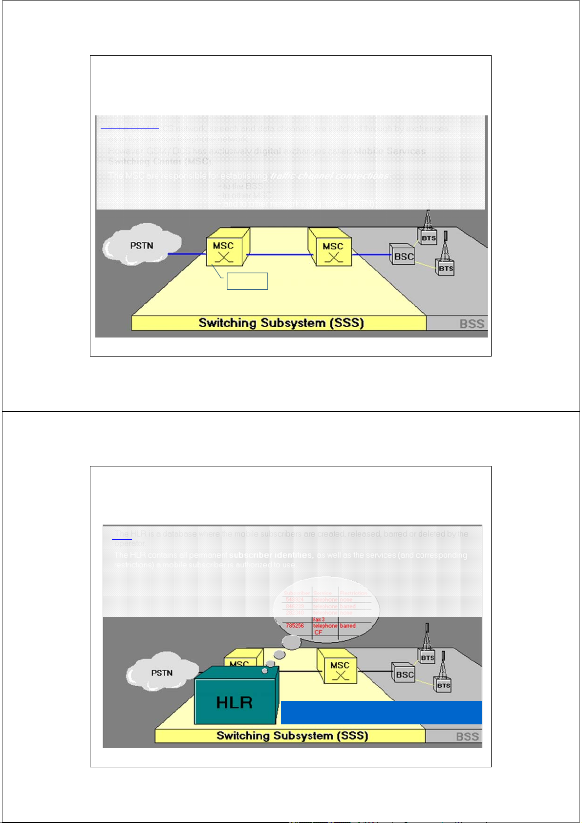
2.2 Phân hệ chuyển mạch NSS (SSS)
NSS: Network Switching Subsystem 30 2/17/2014
Tổng đài di động MSC Chức năng:
• Xử lý cuộc gọi (call procesing).
• Điều khiển chuyển giao (Handover control).
• Quản lý di động (mobility management).
• Xử lý tính cước (billing).
• Tương tác mạng (interworking function):GatewayMSC GMSC 31 2/17/2014
Bộ định vị thường trú HLR
“HLR là cơ sở dữ liệu tham chiếu lưu giữ lâu dài các thông tin về thuê bao”.
• Cá c số nhận dạng: IMSI, MSISDN.
• Các thông tin về thuê bao
• Danh sách dịch vụ MS được/hạn chế sử dụng.
• Số hiệu VLR đang phục vụ MS
HLR: Home Location Register 32 2/17/2014
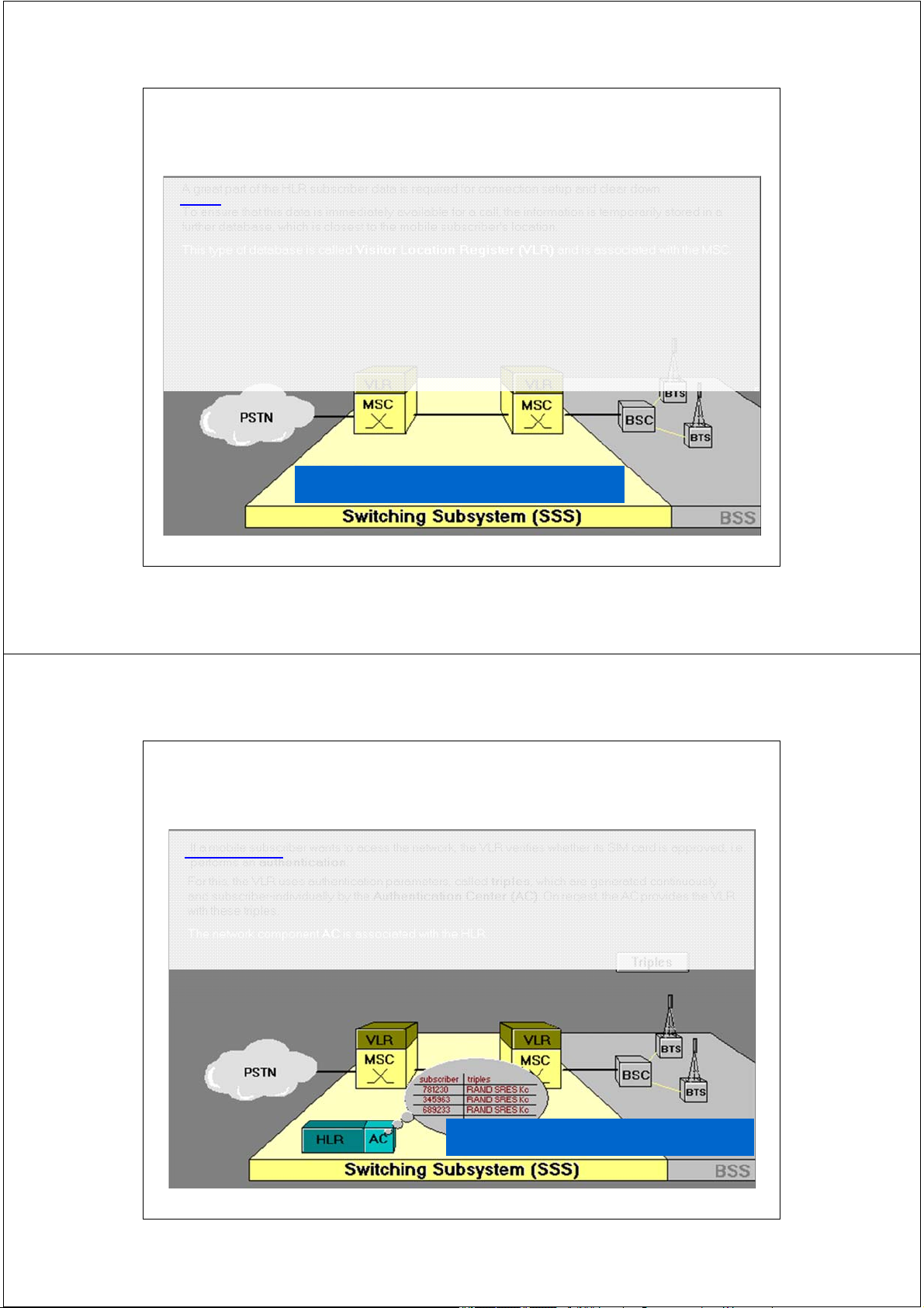
Bộ định vị tạm trú VLR
“VLR là cơ sở dữ liệu trung gian lưu giữ tạm thời
thông tin về thuê bao trong vùng phục vụ MSC/VLR
được tham chiếu từ cơ sở dữ liệu HLR”.
• Các số nhận dạng: IMSI, MSISDN,TMSI.
• Số hiệu nhận dạng vùng định vị đang phục vụ MS.
• Danh sách dịch vụ MS được/hạn chế sử dụng
• Trạng thái của MS (bận: busy; rỗi : idle)
VLR: Visitor Location Register 33 2/17/2014
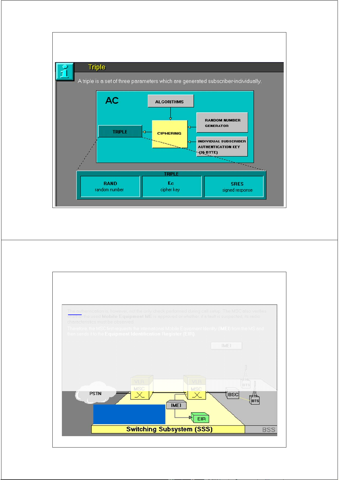
Trung tâm nhận thực AuC
“AuC (AC) là cơ sở dữ liệu lưu giữ mã khóa cá nhân
Ki của các thuê bao và tạo ra bộ ba tham số nhận
thực ‘triple: RAND, Kc,SRES’ khi HLR yêu cầu
để tiến hành quá trình nhận thực thuê bao”.
AuC: Aunthentication Center 34 2/17/2014
Bộ ba thông số nhận thực “triple” 35 2/17/2014
Khối nhận dạng thiết bị EIR
“EIR là cơ sở dữ liệu thông tin về tính hợp lệ của
thiết bị ME qua số IMEI”.
• Một thiết bị sẽ có số IMEI thuộc 1 trong 3 danh sách:
+ Danh sách trắng (white list) -> valid ME
+ Danh sách đen (black list) -> stolen ME
+ Danh sách xám (gray list) -> ME is fauly or do not
meet curent GSM specifications EIR: Equipment Identity Register 36 2/17/2014
Nêu sự khác biệt giữa nhận dạng
thuê bao so với nhận dạng thiết bị
1. Cho phép GSM định tuyến cuộc gọi, tính cước thuê bao di động.
2. Nhận dạng thiết bị bị đánh cắp.
3. Khẳng định thiết bị được cung cấp bởi một nhà cung cấp dịch vụ GSM. 37 2/17/2014
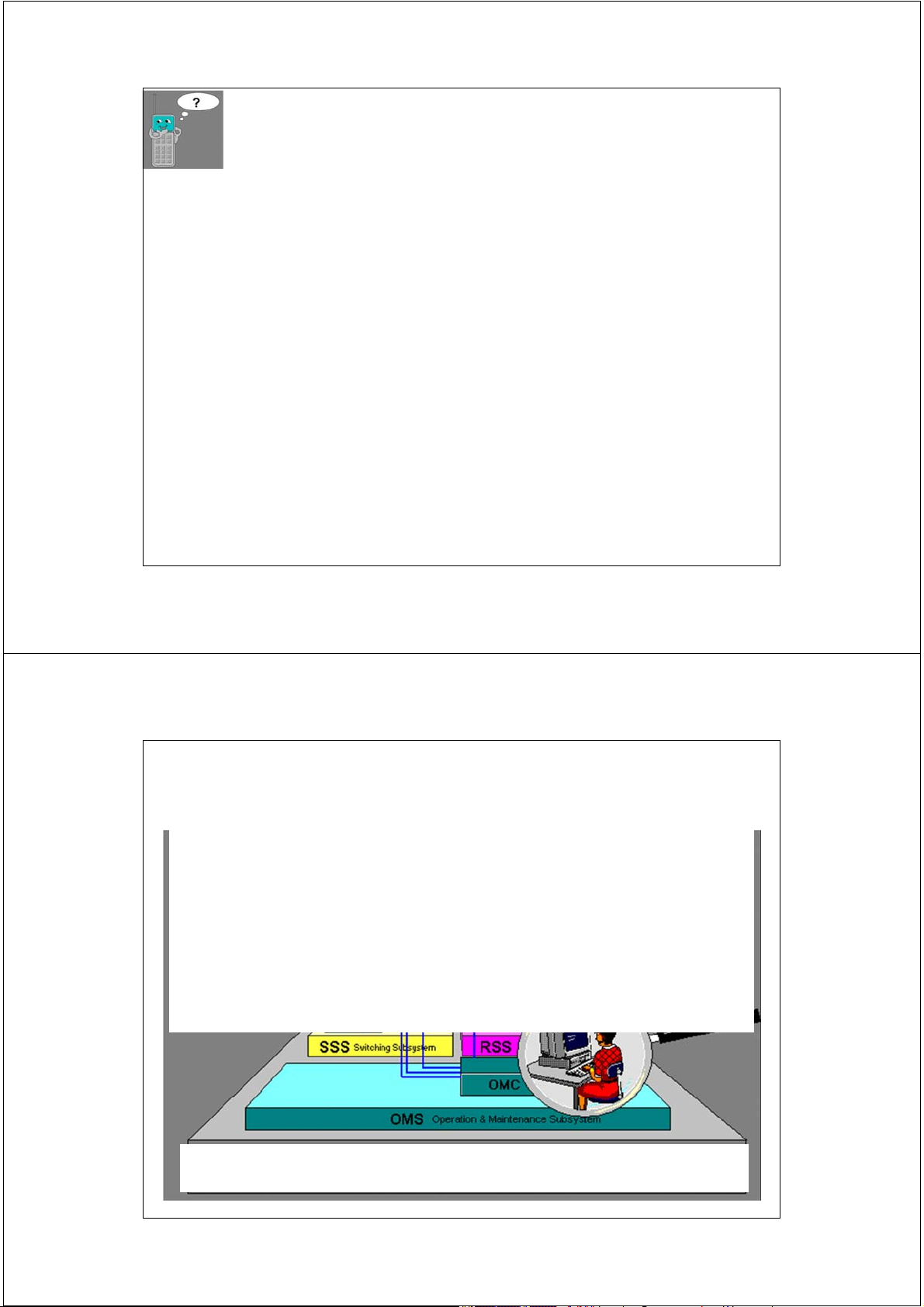
Phân hệ vận hành và bảo dưỡng OMS
• Các thành phần của phân hệ NSS và BSS (BSC,
BTS,TRAU) được điều hành, theo dõi và bảo dưỡng
tập trung thông qua phân hệ OMS.
• OMS có thể bao gồm 1 hoặc nhiều trung tâm vận
hành bảo dưỡng OMC ( Operation & Maintenance Center)
OMS: Operation and Maintenance Subsystem 38 2/17/2014
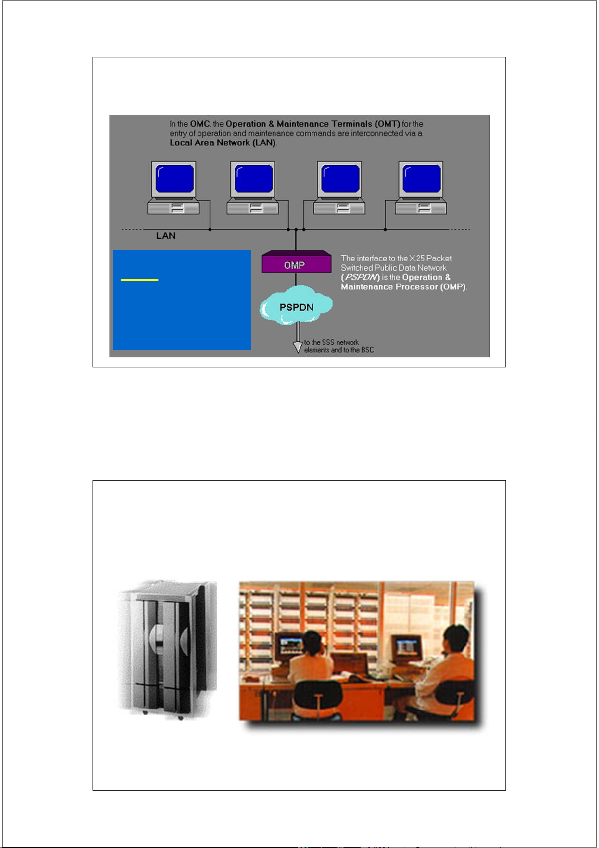
Trung tâm vận hành và bảo dưỡng OMC OMC: Operation and Maintenance Center 39 2/17/2014
Trung tâm vận hành và bảo dưỡng OMC 40 2/17/2014
Trung tâm vận hành và bảo dưỡng OMC • Phân loại OMC:
+ OMC-S (switching): quản lý phân hệ NSS
+ OMC-R (Radio): quản lý phân hệ BSS
• OMC thực hiện các chức năng:
+ Quản lý cảnh báo - Event/alarm manegament.
+ Quán lý lỗi - Fault manegament
+ Quản lý chất lượng – performance manegament.
+ Quản lý cấu hình – configuration manegament.
+ Quản lý bảo mật – sercurity manegament. 41 2/17/2014
GSM network’s functions
A GSM network performs 5 main functions:
• Transmission (data & signalling; MS, BTS, BSC)
• Communication/Connection Management (CM)
• Radio Resources Management (RRM)
• Mobility Management (MM)
• Operation, Administration & Maintenance (OAM) 42 2/17/2014
Các thành phần của mạng GSM 43 2/17/2014
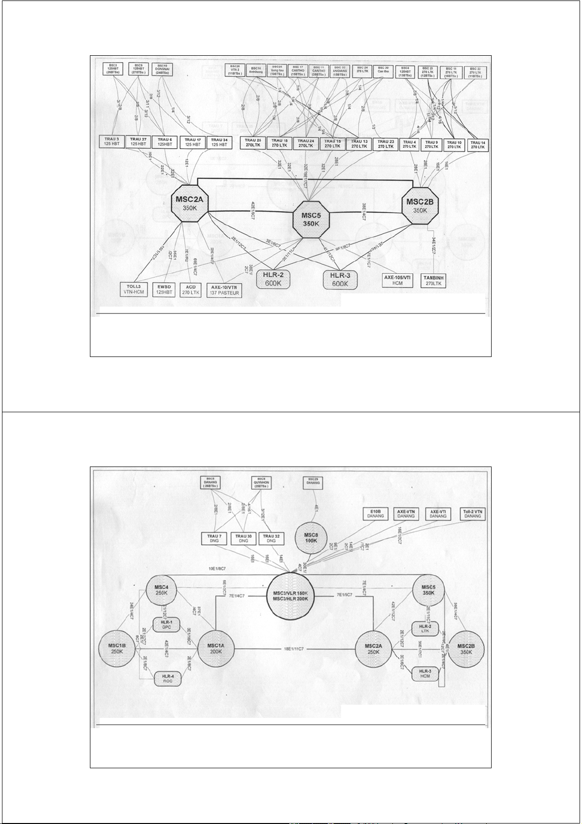
3. Cấu trúc thực tế mạng GSM 44 2/17/2014
GSM network’s structure 45 2/17/2014
GSM network’s structure 46 2/17/2014 47 2/17/2014
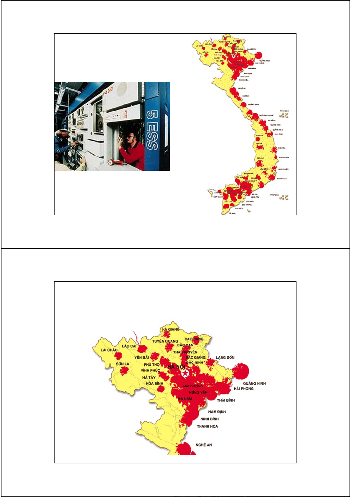
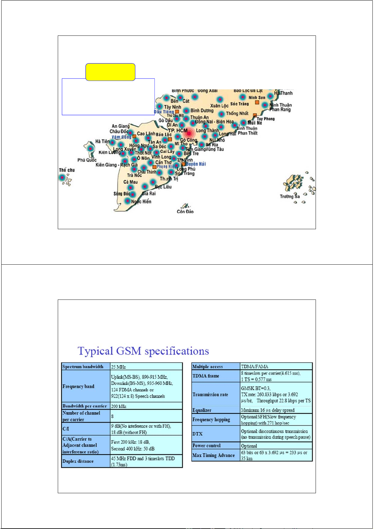
Vùng phủ sóng - Mobiphone VMS 48 2/17/2014
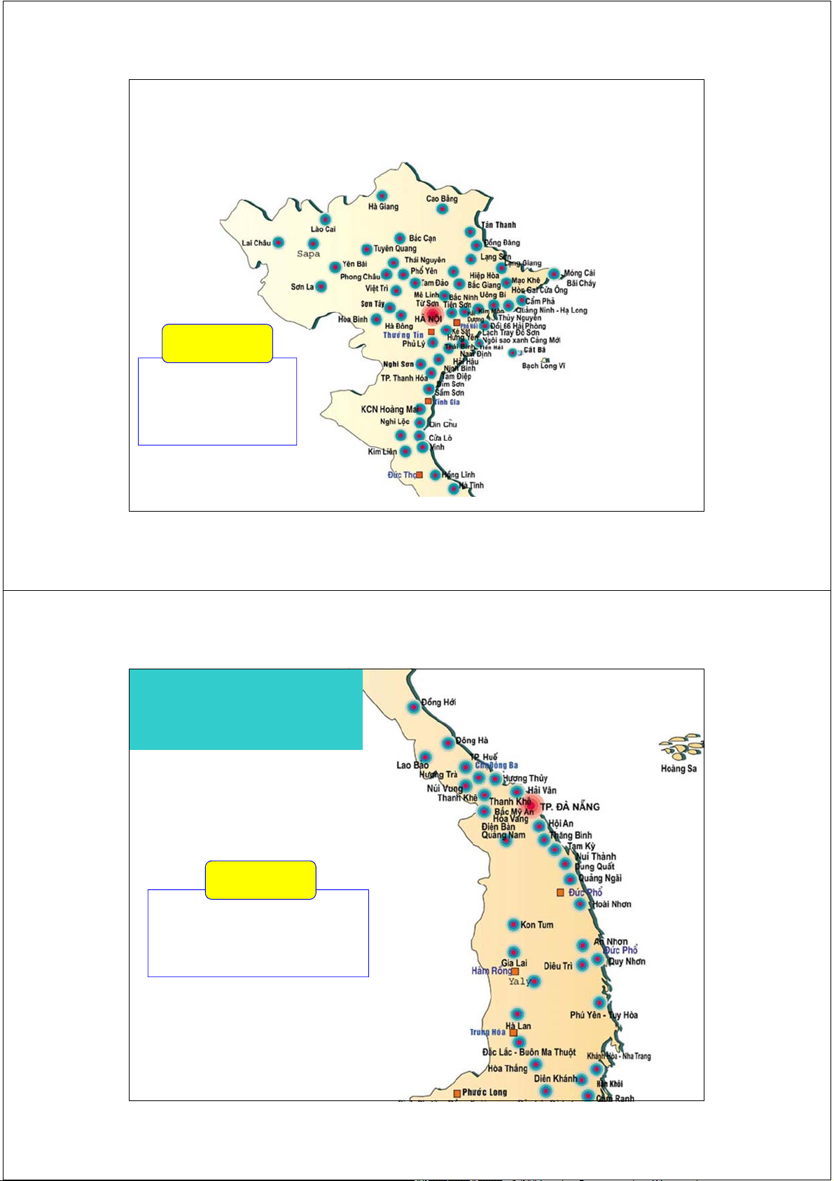
Vùng phủ sóng - Vinaphone Miền Bắc Vùng 1 KV1: Hà Nội và các tỉnh phía Bắc đến Quảng Bình 49 2/17/2014 Vùng phủ sóng - Vinaphone Vùng 3 KV1: Các tỉnh miền Trung
từ Quảng trị đến Khánh hòa và tỉnh Tây nguyên 50 2/17/2014
Vùng phủ sóng - Vinaphone Vùng 2 KV2: TP. Hồ Chí Minh
và các tỉnh phía Nam từ Ninh thuận đến Cà mau 51 2/17/2014
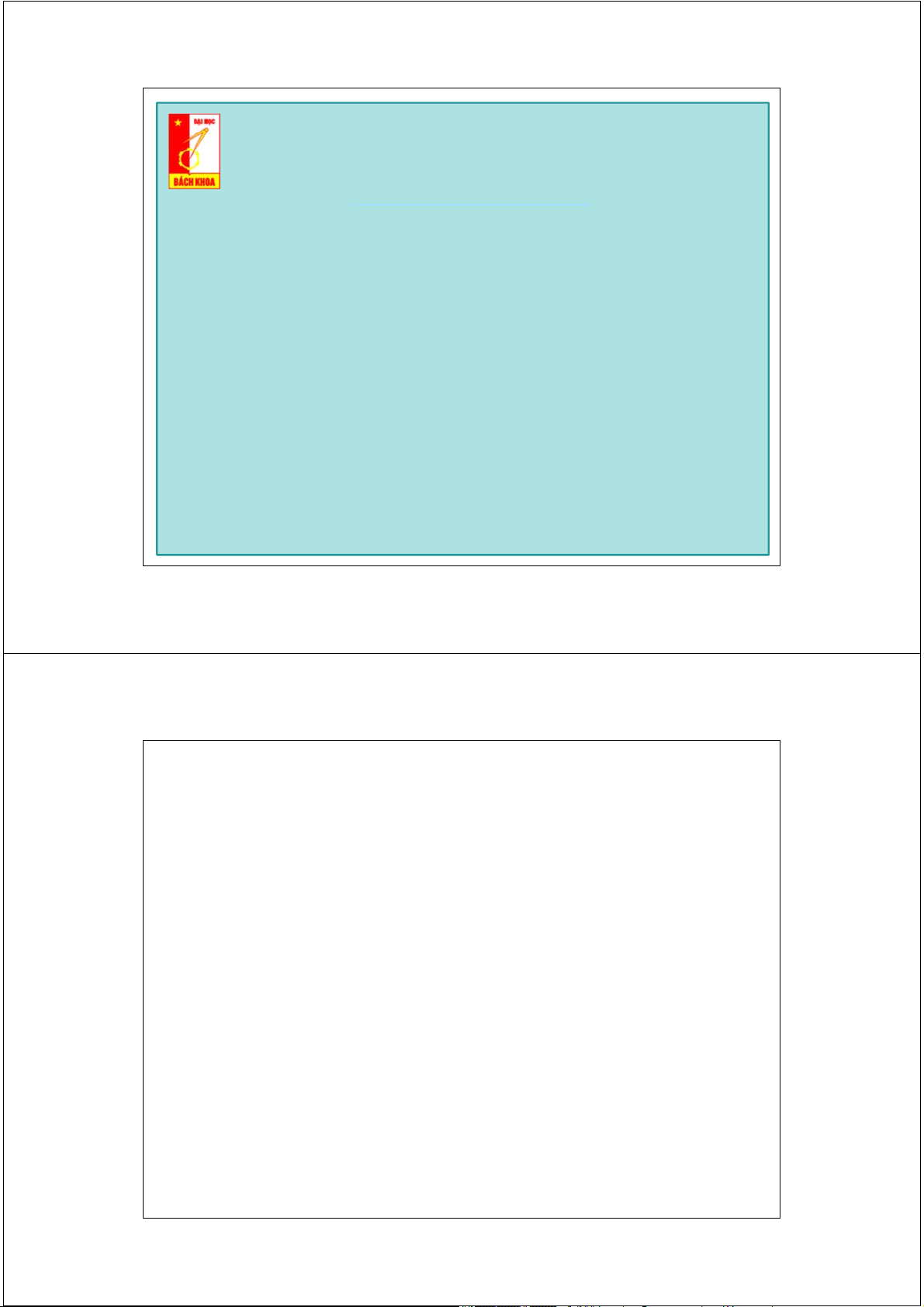
Chỉ tiêu kỹ thuật hệ thống GSM 52 2/17/2014
Trường Đại học Bách Khoa Hà Nội
Viện Điện tử Viễn thông Thông tin di động Mobile Communications
TS. Đỗ Trọng Tuấn
Bộ môn Kỹ thuật thông tin Hà Nội, 04-2011 1 2/17/2014
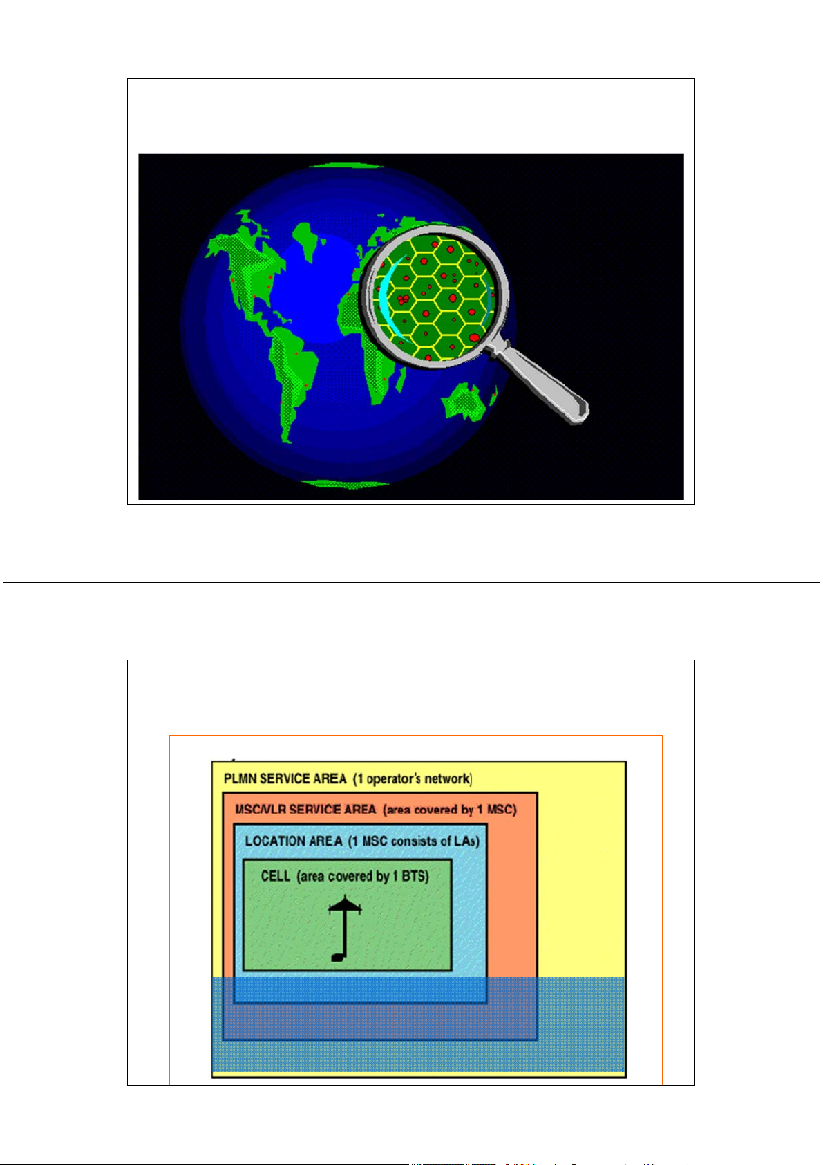
Phân cấp vùng phục vụ trong mạng GSM 2 2/17/2014
Phân cấp vùng phục vụ GSM
Location Information-GSM Service Area Hierarchy 3 2/17/2014
Phân cấp vùng phục vụ GSM
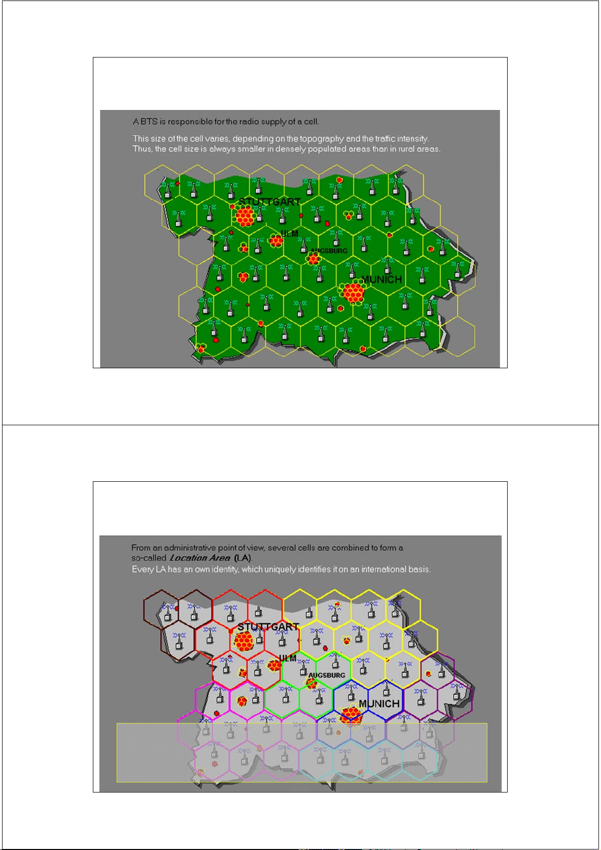
Location Information-GSM Service Area Hierarchy GSM Service Area Service area = the area in which a subscriber an access the network. 4 2/17/2014 Vùng phục vụ PLMN 5 2/17/2014
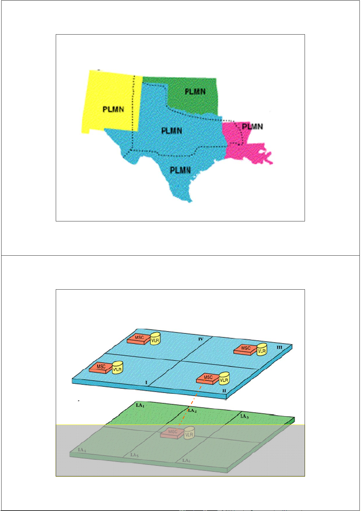
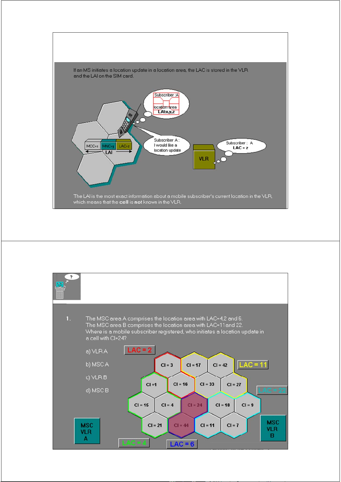
Vùng định vị LAI và vùng phục vụ MSC/VLR
Vùng định vị LA là vùng gồm một số cell do nhà
quy hoạch ấn định tại đó MS có thể di chuyển tự
do mà không cần cập nhật lại vị trí. 6 2/17/2014
Số nhận dạng vùng định vị LAI 3 digits 2 digits 2 Bytes Mobile country Mobile Location Area Code (MCC) Network Code Code (LAC) (MNC)
Số LAI: Location Area Identity => Số nhận dạng vùng định vị 3 digits 2 digits 2 Bytes 2 Bytes Mobile country
Mobile Network Location Area Global Cell Code (MCC) Code (MNC)
Code (LAC) Identity (GCI)
Số nhận dạng ô toàn cầu GCI:
GCI = MCC + MNC + LAC + GCI = LAI + GCI 7 2/17/2014
Phân cấp vùng phục vụ GSM
Location Information-GSM Service Area Hierarchy 8 2/17/2014
Phân cấp vùng phục vụ GSM
Location Information-GSM Service Area Hierarchy 9 2/17/2014
Phân cấp vùng phục vụ GSM
Location Information-GSM Service Area Hierarchy
Số nhận dạng vùng định vị LAI được lưu giữ ở đâu ? 10 2/17/2014
Phân cấp vùng phục vụ GSM
Location Information-GSM Service Area Hierarchy 11 2/17/2014 Ví dụ 12 2/17/2014
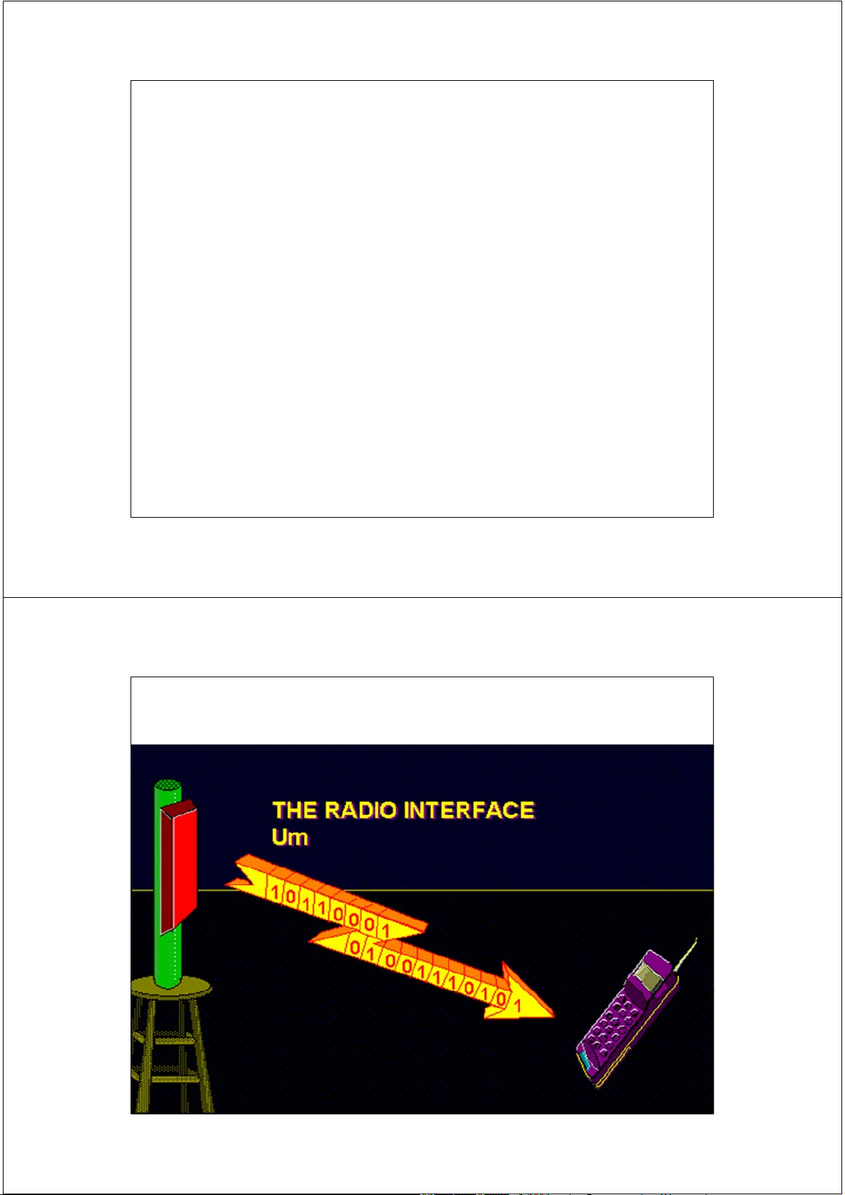
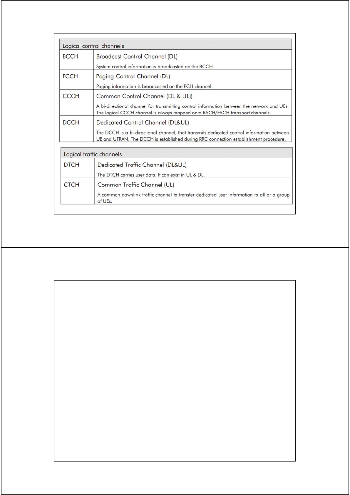
Kênh tại giao diện vô tuyến Um 13 2/17/2014 Giao diện vô tuyến Um 14 2/17/2014 FDMA Frequency Channel Time 15 2/17/2014
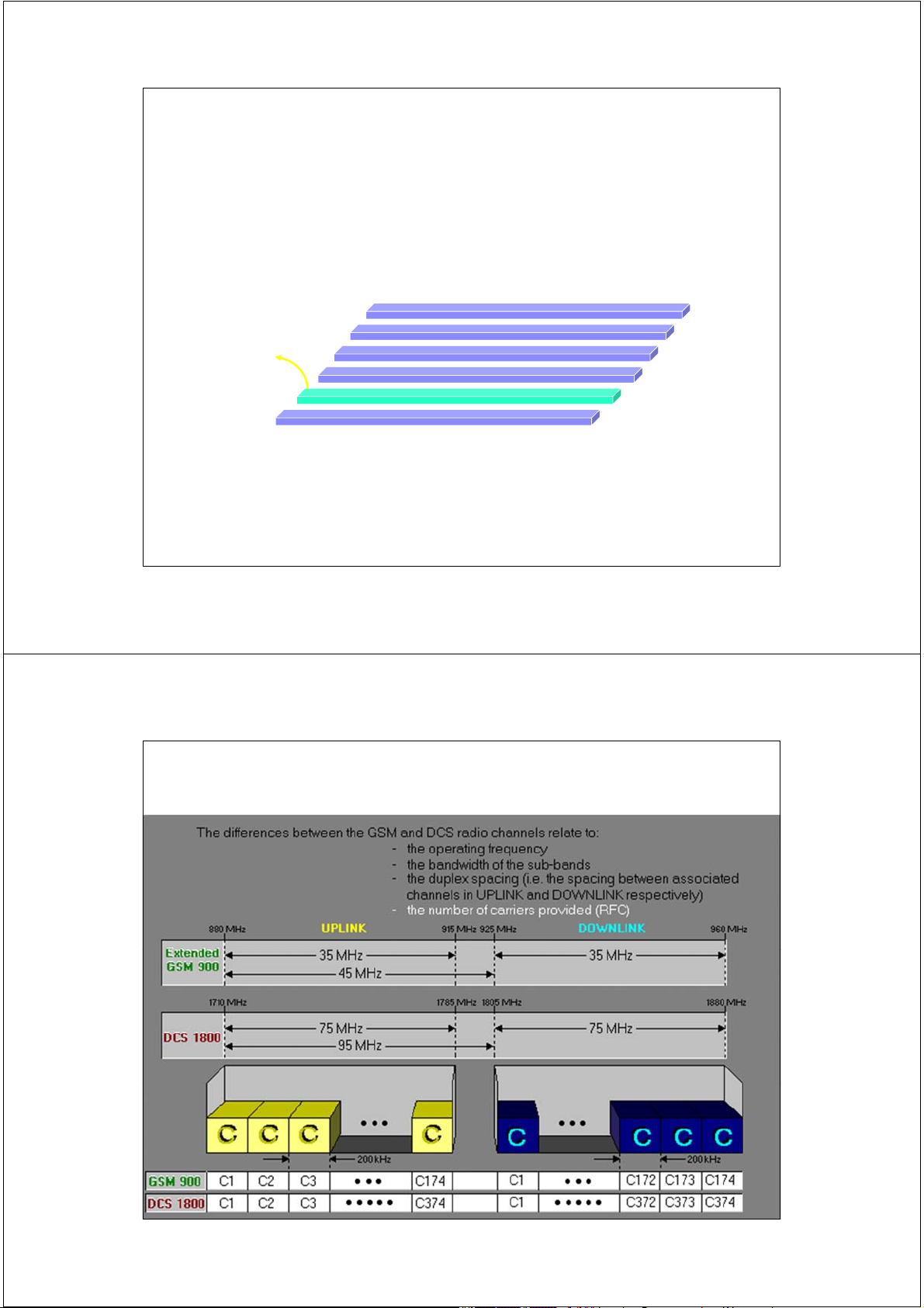
Kênh tần số trong hệ thống GSM và DCS 16 2/17/2014 TDMA Frequency Time Slot Channel Time 0 1 2 3 4 5 6 7 17 2/17/2014 Khái niệm
Kênh vật lý là phương tiện truyền tải thông tin. Tại Um:
• Kết hợp sử dụng 2 phương thức đa truy nhập FDMA và TDMA. • Kênh vật lý CH = TS є i ARFCNj
Kênh logic là thông tin mang trên kênh vật lý 18 2/17/2014
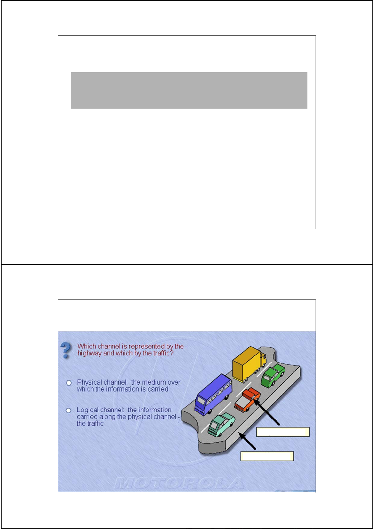
Channels : differentiating between Physical and Logical channels
Physical channels : The combination of an ARFCN
and a time slot defines a physical channel.
Logical channels : These are channels specified by
GSM which are mapped on physical channels. 19 2/17/2014
Kênh vật lý và kênh logic 20 2/17/2014
Chế độ làm việc song công - Duplex 960 MHz
FDD: Frequency Division Duplex 124
TDD: Time Division Duplex 959.8MHz 123 GSM900 utilizes two TS: Ti bands me slot of 25 MHz. 890- …… DOWNLINK .
915 MHz band is used for uplink Downlink (TDMA while the frame) = 8 TS ……
935-960 MHz is used for downlink. 2 0 1 2 200KHz 3 4 5 6 7 935.2 Mhz 1
The frequency bands are divided into 200 935 MHz
KHz wide channels called ARFCNs (Absolute Radio Frequency FDD Data burst = Channel Numbers)
156.25 bit periods = 576.9s i.e. 915 MHz
there are 124 ARFCNs are used. 124 914.8 MHz Each ARFCN TDD
supports 8 users with each user 123
transmitting / receiving on a particular time 45 MHz …… Delay 0 1 2 3 4 5 6 7 . slot (TS). UPLINK 200KHz …… Uplink (TDMA frame) 2 890.2 MHz 1 890 MHz
Therefore 1 TDMA frame = 156.25 x 8 = 1250 bits Duplex methods
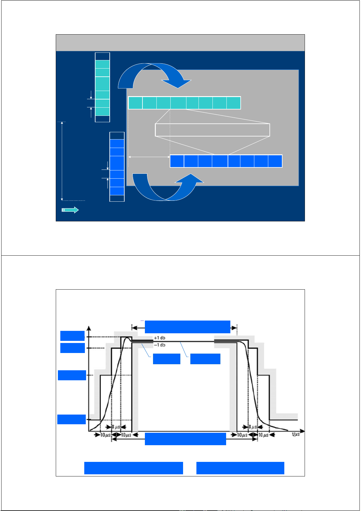
and has a duration of 576.92s x 8 = 4.615 ms 21 2/17/2014 Time Slot & Burst P (dB)
148 bits = 542,8 µs +4 dB - 6 dB ± 1 dB 34 dBm - 30 dB - 70 dB 156,25 bits = 577 µs t (µs)
Mức công suất phát của MS biến thiên theo thời gian
Time Slot: khe thời gian
Busrt: Cụm thông tin 22 2/17/2014
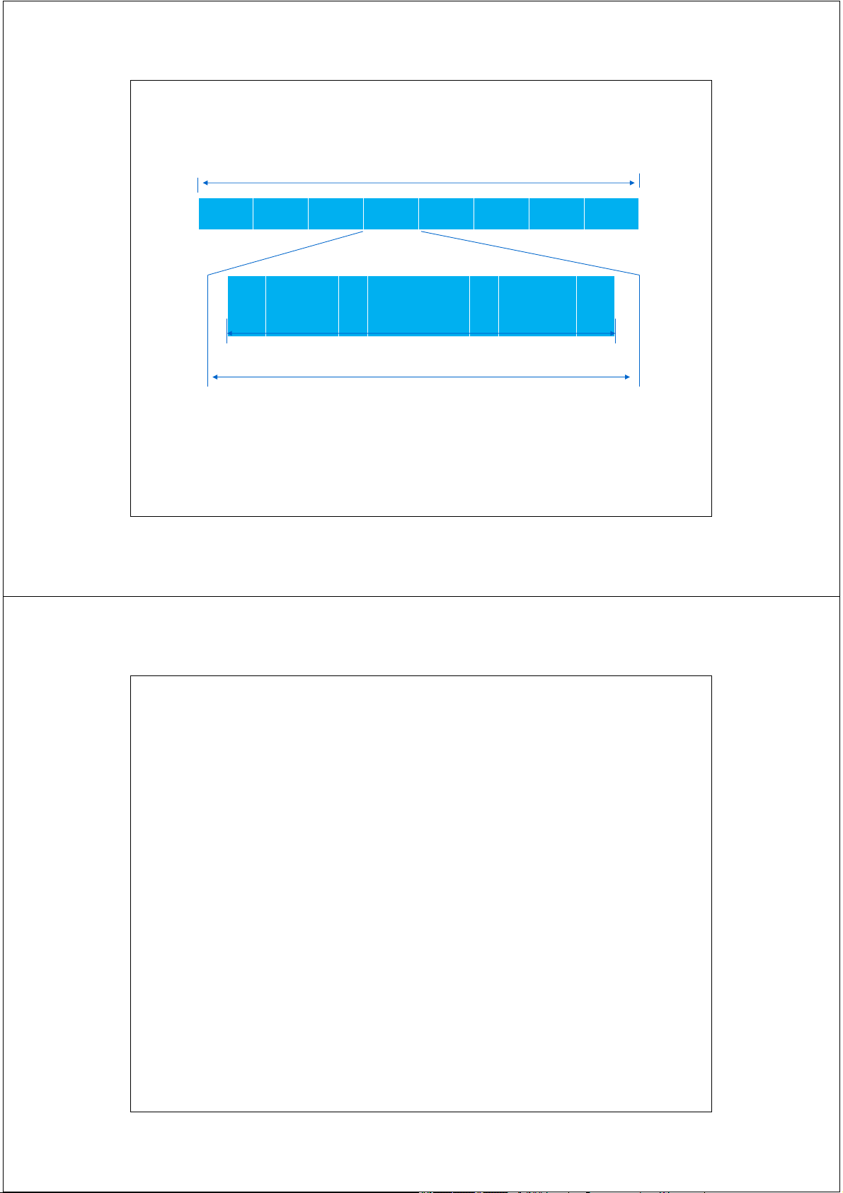
Phân cấp cấu trúc khung - Frame hierarchy
1 hyperframe = 2048 superframes = 2715648 TDMA frames 0 1 2 3
…… 2044 2045 2046 2047 3 h 28 min 53.76 s
1 superframe = 51 (26frame) multiframes
OR 26 (51 frame) multiframes 6.12 s 0 1 2 3 ………. 47 48 49 50 0 1 ………. 24 25 26 * 51 = 1326 TDMA Frames
1 trafic multiframe = 26TDMA frames
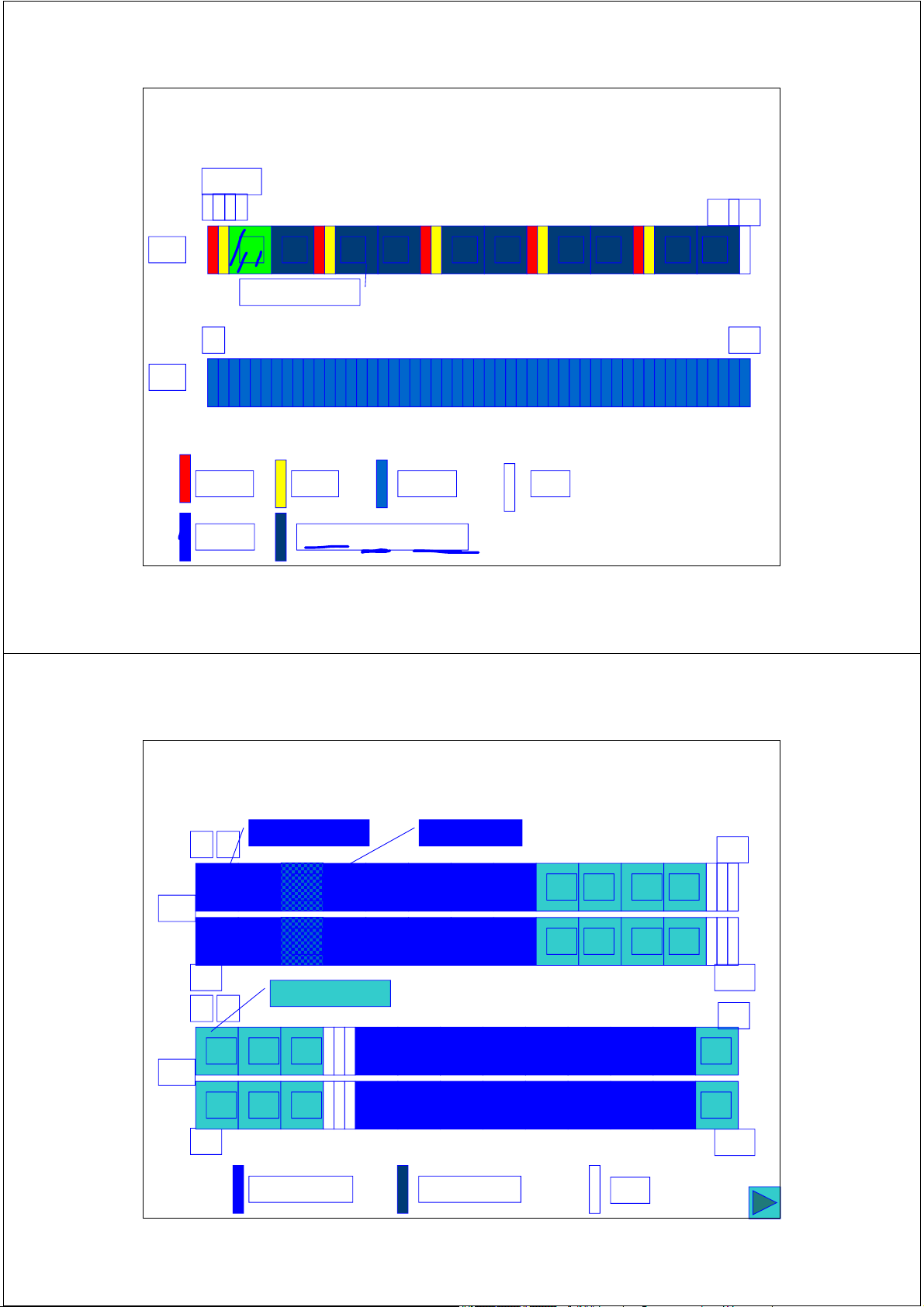
1 control multiframe = 51TDMA frames T0 T1 ….. T11 S T12 ….. T24 I T0 T1 T2 T3 …. ….. ….. T48 T49 T50 120 ms 235.4 ms 0 1 ... 6 7 4.615 ms slot 577 µs TDMA Frame burst 23 2/17/2014
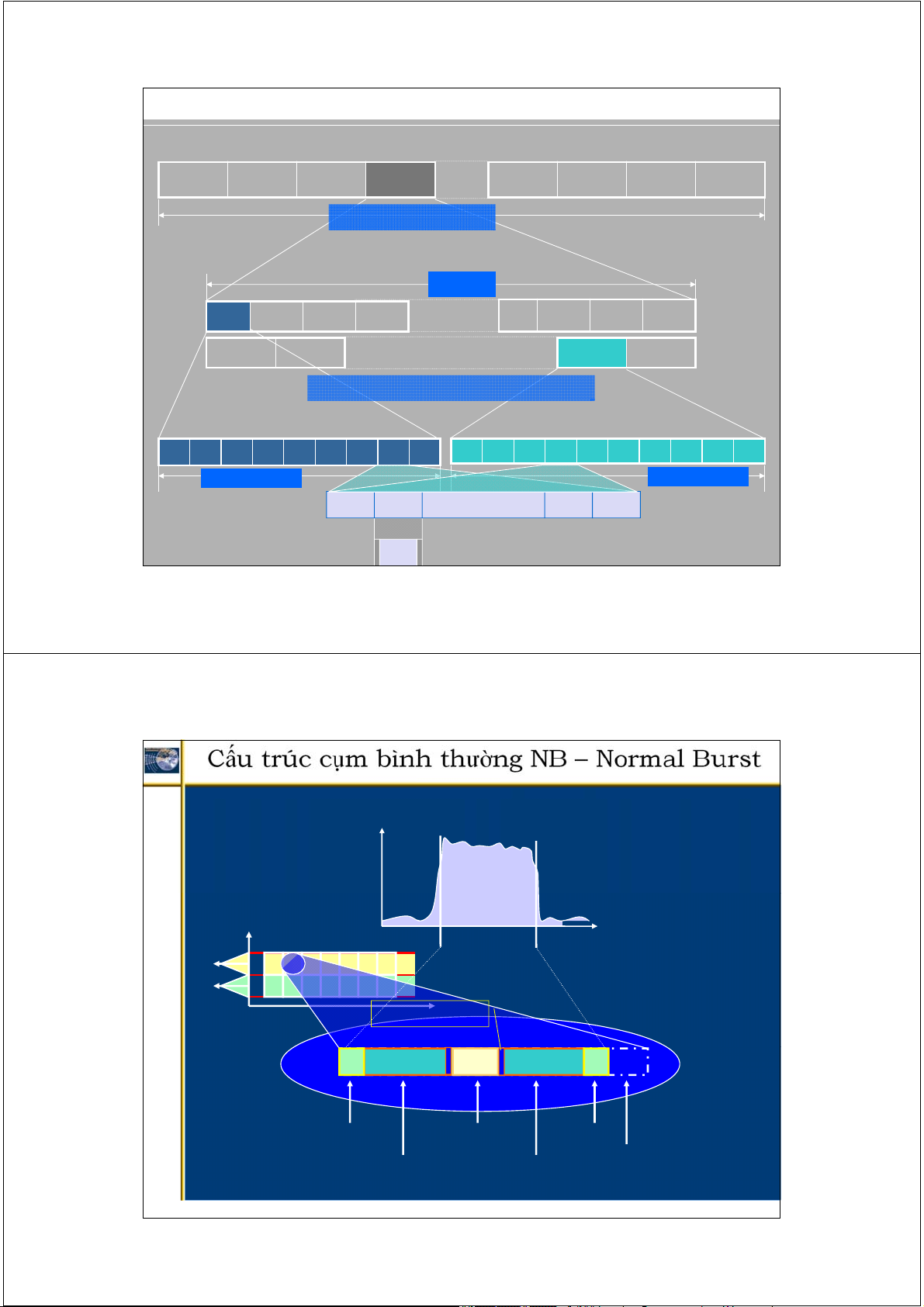
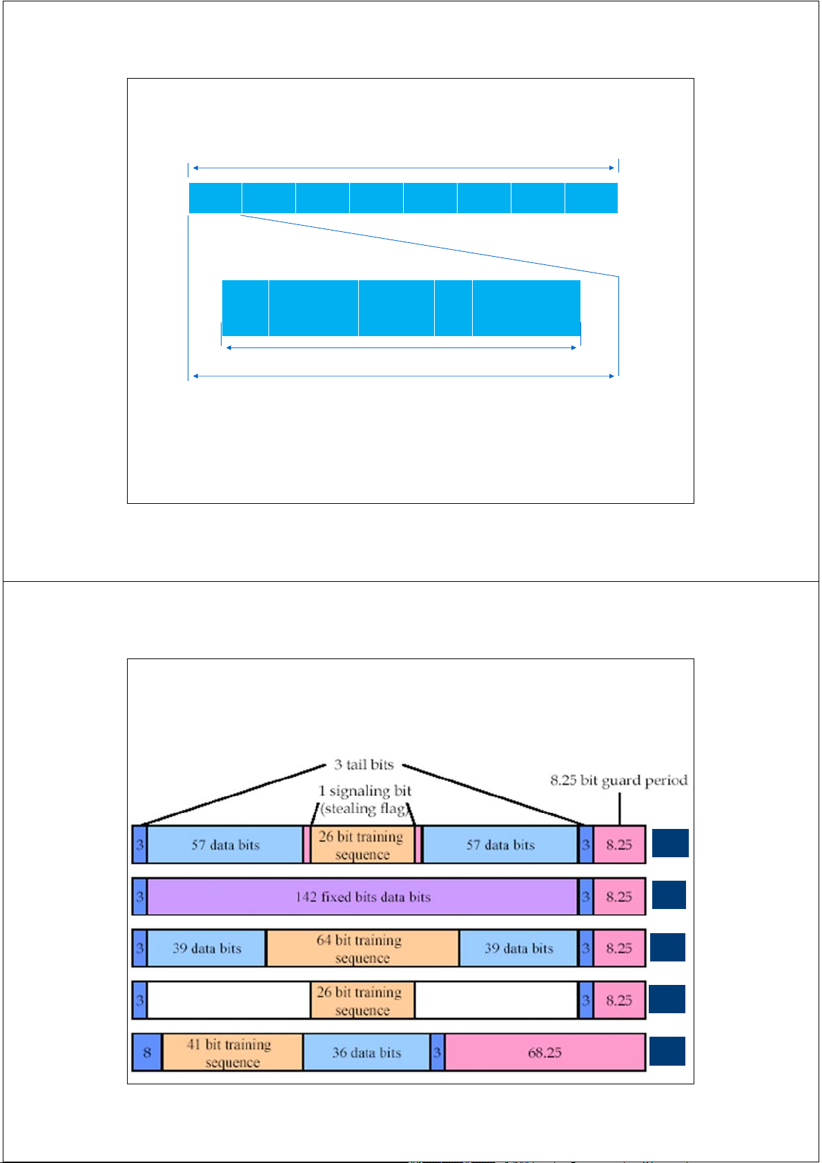
Cấu trúc cụm bình thường NB – Normal Burst Power p(t) t useful part
156.25 Bits in 576.923 s f 0 1 2 ... 7 0 1 ... 2
(3.6923 s/Bit) f 0 1 2 ... 7 0 1 ... 1 Stealing Flag 3 Tail Bits 26 Training Bits 3 Tail Bits 8.25 Bits Guard Period 2 x 57 Encrypted Bits 24 2/17/2014 Normal Burst 4.615ms 0 1 2 3 4 5 6 7 TB: tail bit TB Data S Training S Data TB 3 57 F 26 F 57 3 1 1 148 bits 156.25 bits = 0.577ms
• To carry information on the TCH and all control channels except for RACH, SCH and FCCH
• The two sets of encrypted 57 bits are data or speech ……. 25 2/17/2014 Normal Burst
•The stealing flag (SF) indicates whether the burst was stolen for signaling or not.
•The 3 tail bits are (0,0,0) and is used as the start/stop pattern.
• The GP (guard period of 8.25 is used to prevent overlapping of frames
•The 26 training bits is a known bit sequence to get an
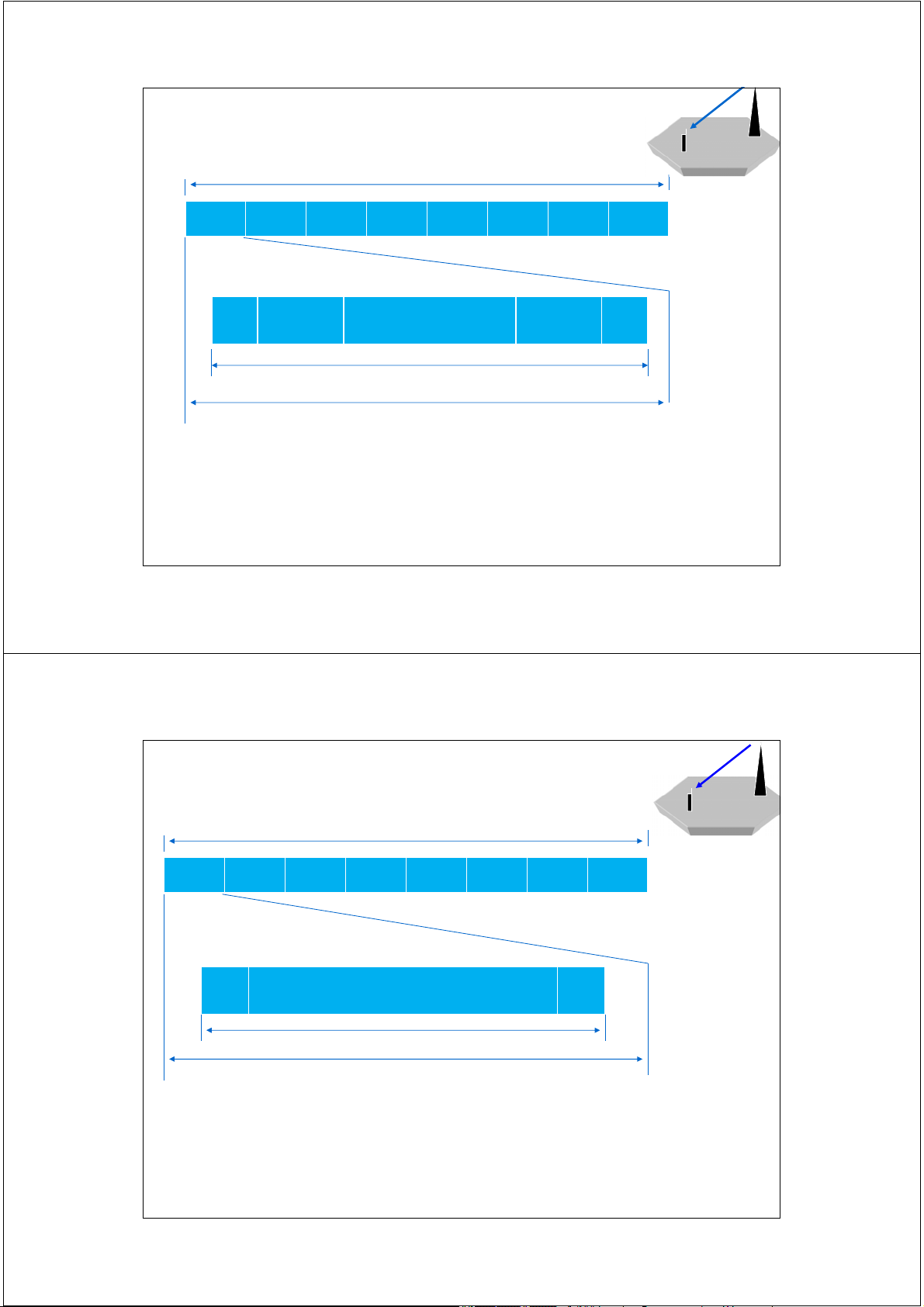
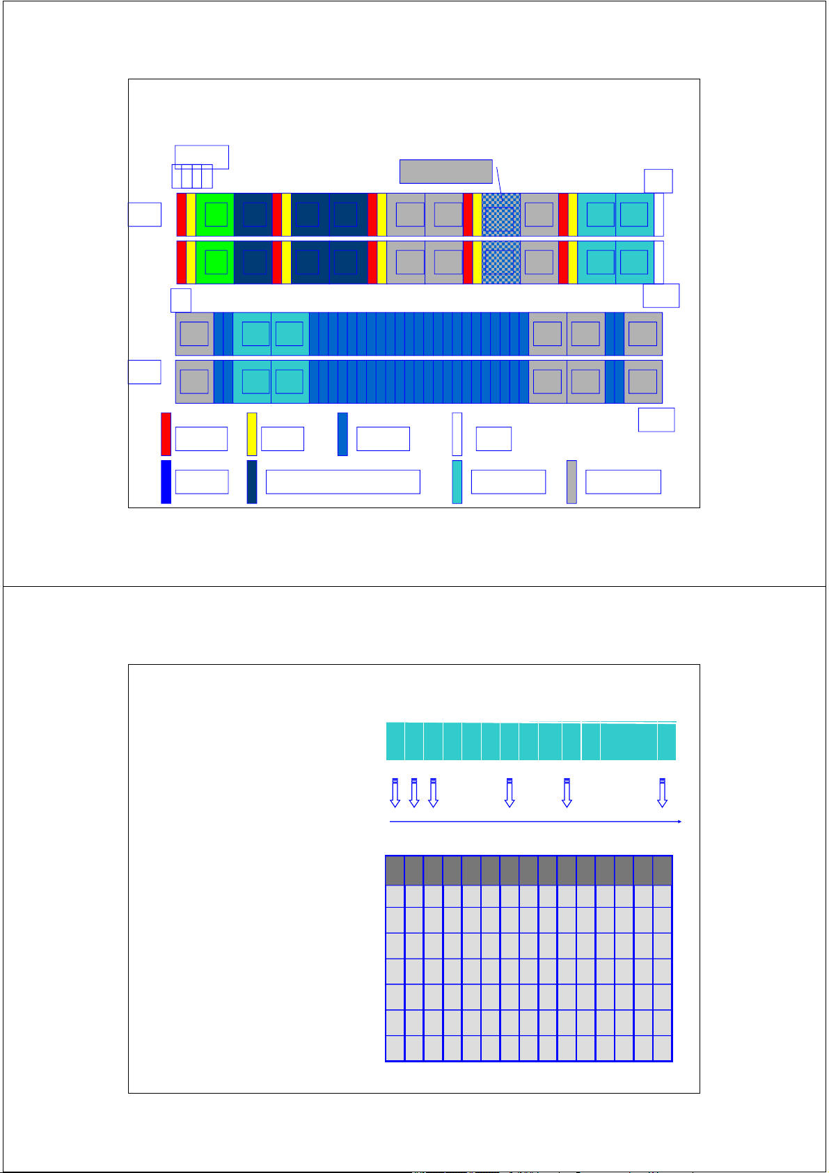
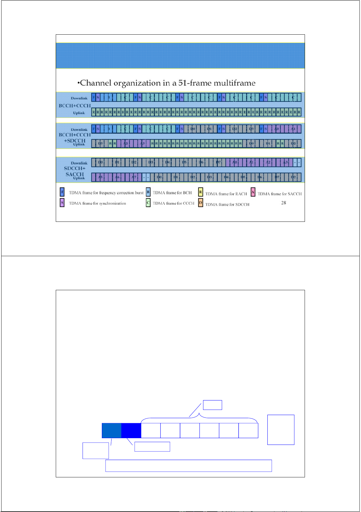
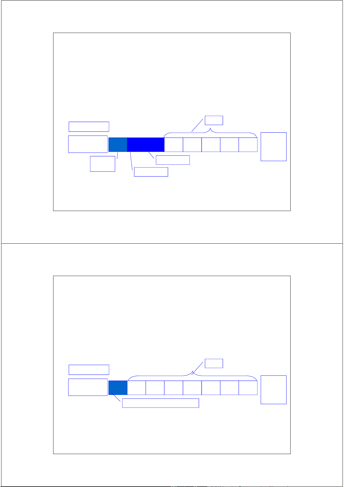
estimate of how the channel is affected by interference 26 2/17/2014 Synchronization Burst BTS MTS 4.615ms 0 1 2 3 4 5 6 7 TB
Encrypted Extended training bits Encrypted TB 3 Bits 39 64 Bits 39 3 148 bits 156.25 bits = 0.577ms
• This burst is used for time synchronization of the mobile
• The long training sequence is a synchronization sequence
• The encrypted 78 bits carry the information of the TDMA frame
number and the BSIC (Base Tranceiver Station Identity Code) 27 2/17/2014 Frequency Correction Burst BTS 4.615ms MTS 0 1 2 3 4 5 6 7 TB Fixed all zeros TB 3 142 3 148 bits 156.25 bits = 0.577ms
• This burst is used for frequency synchronization of the mobile
• The sequence of fixed zeros is equivalent to an unmodulated carrier. 28 2/17/2014 Access Burst 4.615ms 0 1 2 3 4 5 6 7 TB Syn. Encrypted TB Additional Sequence message guard time 8 41 36 3 60 148 bits 156.25 bits = 0.577ms
• The random access burst has a longer guard period since the mobile
does not know the timing advance when it randomly accesses the system 29 2/17/2014
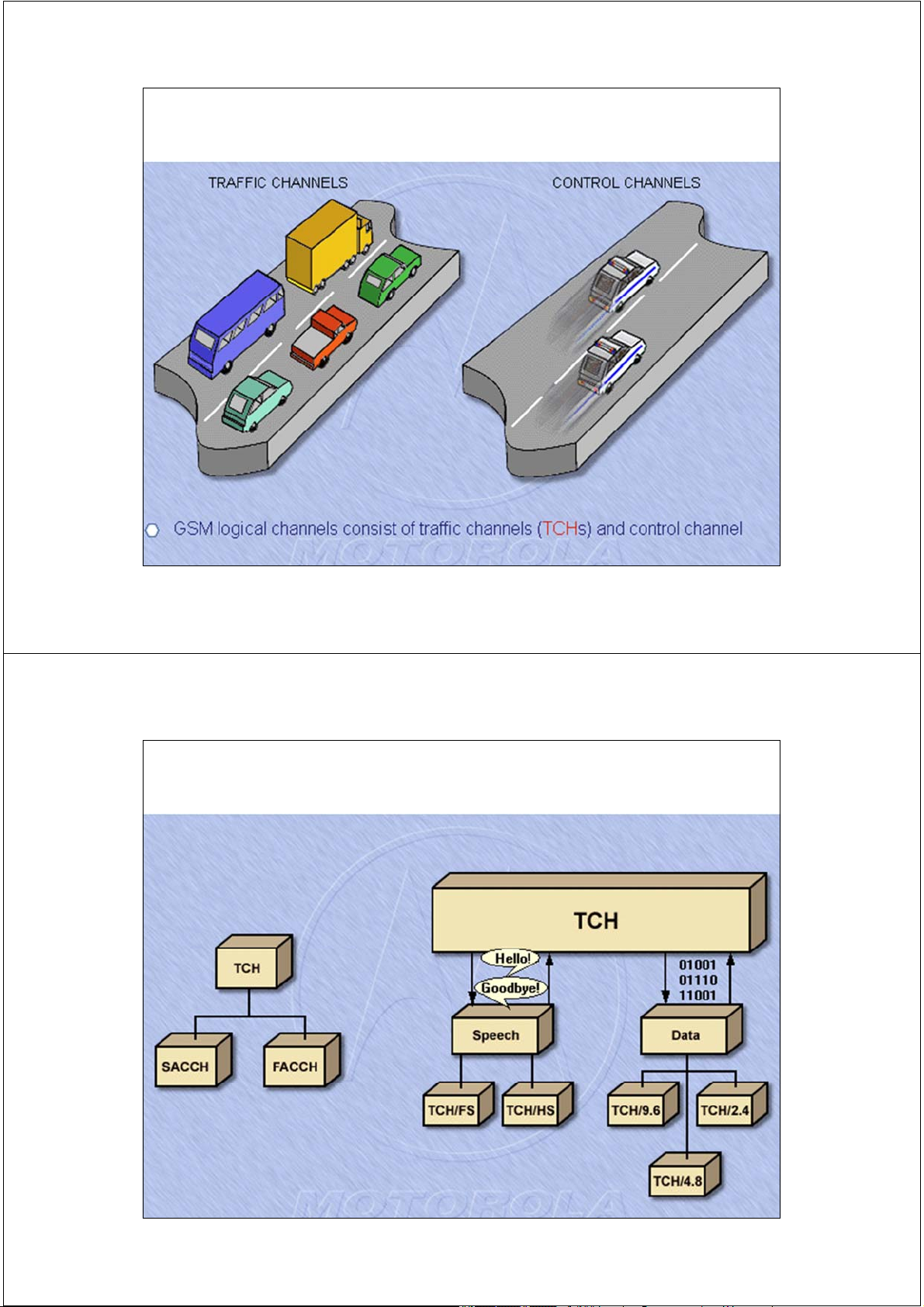
Cấu trúc cụm tại giao diện vô tuyến NB FB SB DB AB 30 2/17/2014 Kênh logic 31 2/17/2014 Kênh lưu lượng - TCH 32 2/17/2014 Kênh lưu lượng TCH
TCH/FS : for speech digitized at raw data
rate of 13 kbps (FS: Full Speech): Bm
TCH/HR: for speech digitized at raw data
rate of 6.5 kbps (HS: Half Speech):Lm
TCH/9.6 -> data transfer rate at 9.6 kbps TCH/4.8, TCH/2.4 . . . 33 2/17/2014 Kênh điều khiển - CCH 34 2/17/2014 Control Channels Functions:
• To help the MS find the control channels.
• To provide information about
- voice and control channel repetition cycle. - parameters in the cell. - surrounding cells. - paging.
• To allow random access attempts by the MS. 35 2/17/2014
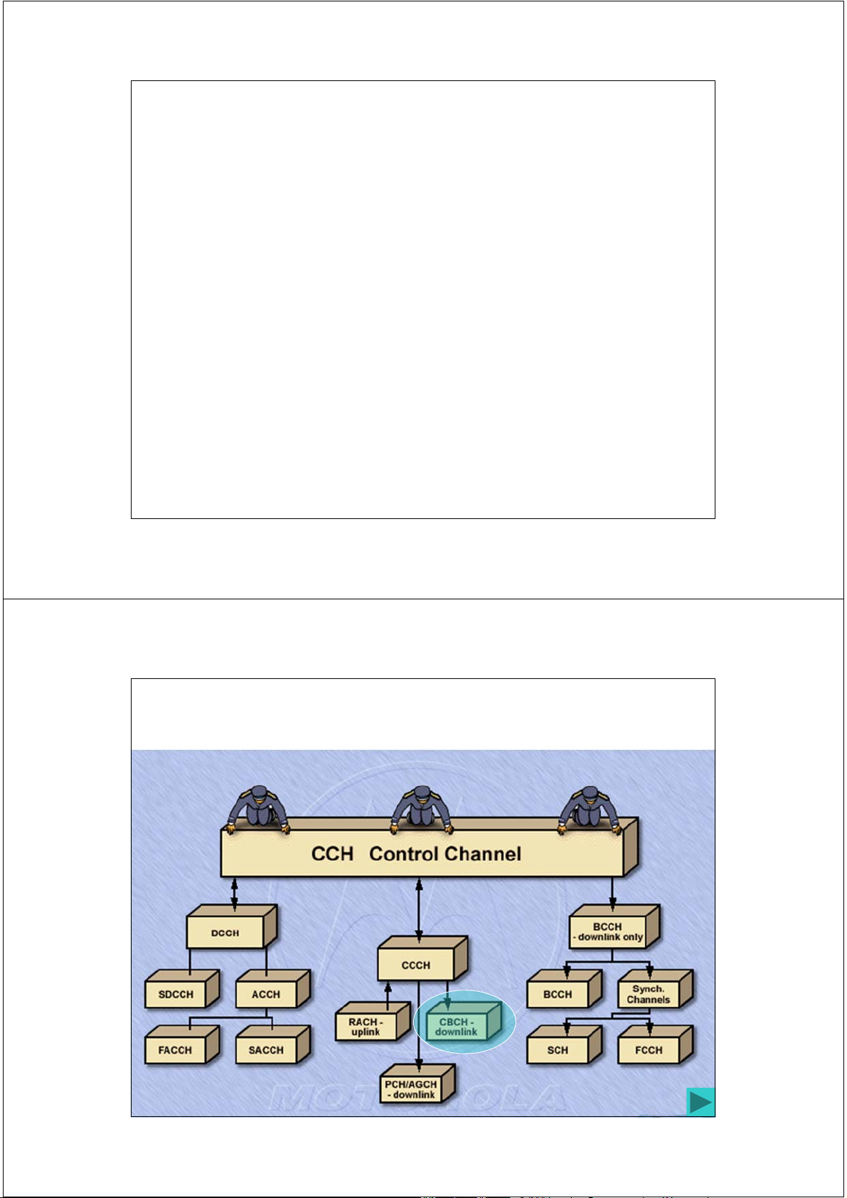
Nhóm kênh điều khiển quảng bá BCH
In general mapped to BCCH ARFCN on TS0.
Broadcast control channels consist of: -
Kênh điều khiển quản bá: BCCH - Broadcast Control Channel . -
Kênh hiệu chỉnh tần số FCCH – Frequency Correction Channel. -
Kênh đồng bộ SCH - Synchronization Channel 36 2/17/2014
Broadcast Control Channel (BCCH)
Serves as a Beacon for the Cell
Country Code (CC) and the Network Code (NC)
Location Area Identity (LAI) and Cell identity
List of neighboring cells which should be monitored by MS
List of frequencies used in the cell 37 2/17/2014
Frequency Correction Channel-FCCH
Allows each user unit to synchronize its
internal frequency standard with BTS
Repeated each 10 frame in control multiframe 38 2/17/2014 Synchronization Channel (SCH) Contains:
• Identification of base station for mobile (BSIC).
• Frame synchronize with BTS ( 0 to 2715647) • Timing advancement command
Transmitted just after FCCH , i.e. after
each 10 frames in control multiframe. 39 2/17/2014
Các kênh điều khiển chung CCCH
In general mapped to BCCH ARFCN on TS0.
Common control channels consist of: -
Kênh tìm gọi: PCH ( Paging CHannel, forward channel), -
Kênh truy nhập ngẫu nhiên RACH ( RANDOM Access CHannel, reverse channel). -
Kênh cho phép truy nhập AGCH ( Access Grant CHannel, forward channel). 40 2/17/2014 Kênh tìm gọi PCH functions:
• Paging signal from BS to to all mobile in the cell.
• Notifies one mobile of an incoming call, by
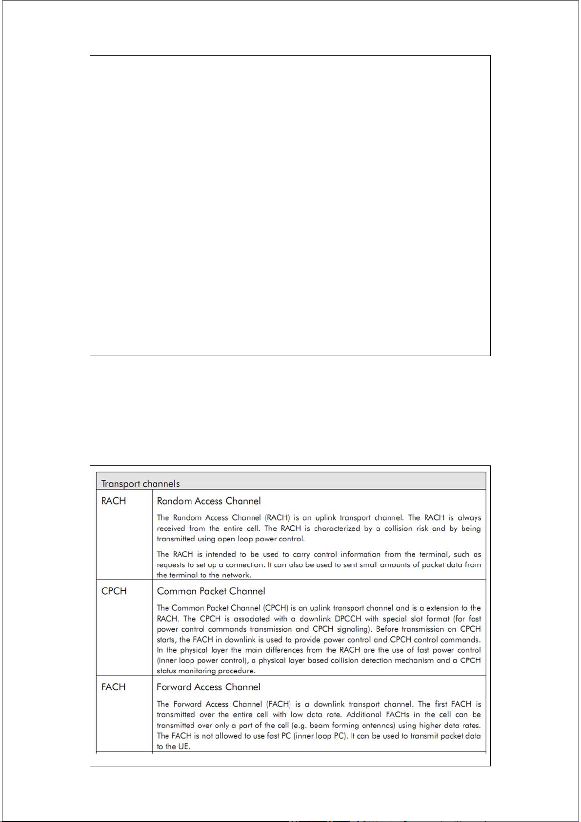
sending IMSI/TMSI to target subscriber along with request for ack on RACH. 41 2/17/2014 Common control channels, CCCH RACH
• RACH is reverse channel for user to BTS ack for a Page.
• Also used by mobiles to originate a call.
• The BTS responds by assigning a Stand
Alone Dedicated channel (SDCCH) for
signalling during a call. This is done on AGCH. 42 2/17/2014 Common control channels, CCCH
AGCH ( Access Grant CHannel)
• AGCH is the final CCCH mesg to subscriber
before it moves off from Control Channel. 43 2/17/2014 Dedicated Control Channels
Three types of Dedicated Channel,
Bidirectional like traffic channels.
Like TCH, they exist on any channel except TS0 of BCCH ARFCN
Used for providing signaling service
required by a particular user during a call. 44 2/17/2014 Dedicated Control Channels
SDCCH ( stand alone dedicated control channel)
• This ensures that MS and BS remain
connected while BS and MSC verify
subscriber identity before BS allocate
resource ( TCH assignmnet) to MS.
• SDCCH may be assigned their own physical channel 45 2/17/2014
What function does Stand-Alone Dedicated Control channel (SDCCH) serve? Used by MS for call setup Authentication BTS MTS Location Updating
(Bi-directional)
Short message service (SMS) Back 46 2/17/2014 Dedicated Control Channels
Slow Associated Control Channel
• Always associated with a traffic channel TCH
or maps to a SDCCH phy channel.
SACCH of transmitted every 13 (26 for
half rate) TDMA frames i.e on each
speech multiframe, 8 TS is used for 8
users ( or 16 users for half rate). 47 2/17/2014
A Slow Associated Control channel (SACCH) is associated
with both a TCH and a SDCCH DOWNLINK: Power control BTS MTS Timing Advance information
(Bi-directional) UPLINK
Receive Signal Strength Indicator Quality reports Back 48 2/17/2014 Dedicated Control Channels
FACCH: Fast Associated Control Channels:
FACCH contains same type of signaling data
(but urgent, like handoff request) and used
when SDCCH has not been dedicated for a particular user.
This is done by stealing frames from TCH forward channel burst.
Two special bits called S bits in one TS, When
set indicates that data is FACCH data and not user data. 49 2/17/2014 ξ3. Tổ hợp kênh và cấu trúc đa khung 50 2/17/2014
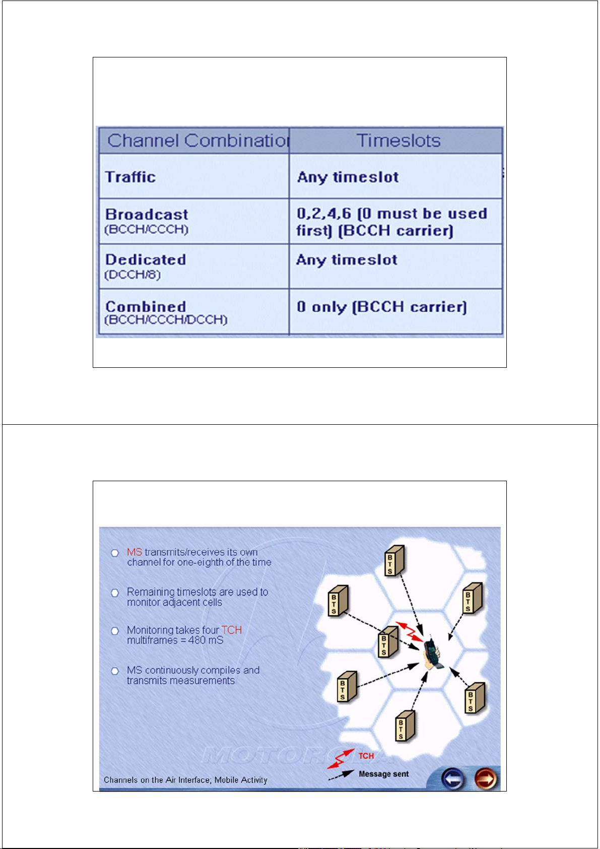
Tổ hợp kênh - Channel combinations
Trên 1 kênh vật lý có thể mang 1 trong các tổ hợp kênh sau: - TCH/F + FACCH/F + SACCH/F - TCH/H + FACCH/H + SACCH/H - FCCH + SCH + BCCH + CCCH -
FCCH + SCH + BCCH + CCCH + SDCCH/4 + SACCH/4 - SDCCH/8 + SACCH/8 51 2/17/2014
Đa khung lưu lượng toàn tốc MF26
Tại 1 thời điểm: TS2 sẽ phục vụ 1 MS TDMA TDMA Frame 0 TDMA Frame 1 slots
0 1 2 3 4 5 6 7 0 1 2 3 4 5 6 7 0
0 1 2 3 4 5 6 7 8 9 10 11 12 13 • • 25 TDMA Frames TCH SACCH on a given channel Traffic Signaling (S) full rate: toàn tốc 52 2/17/2014 Đa khung lưu lượng - MF26 T0 T1 ….. T11 S T13 ….. T24 I T: TCH :Traffic channel S : SACCH : Slow Associated Control Frame channel Time number
0 1 2 ………… 12 13 ……….….. 25 slots 0 T T T T T s T T T I 1 s 2 s 3 s 4 s 5 s 6 s 7 s 53 2/17/2014
Đa khung lưu lượng bán tốc 2
Tại 1 thời điểm: TS2 sẽ phục vụ 2 MS TS2 2
0 1 2 3 4 5 6 7 0 1 2 3 4 5 6 7 0 1 2 TDMA Frame 0 TDMA Frame 1
0 1 2 3 4 5 6 7 8 9 10 11 12 13 • • 25 Burst for one user 0 1 2 3 4 5 6 7 • • • • • • • • 25 Burst for another user half rate: Bán tốc 54 2/17/2014
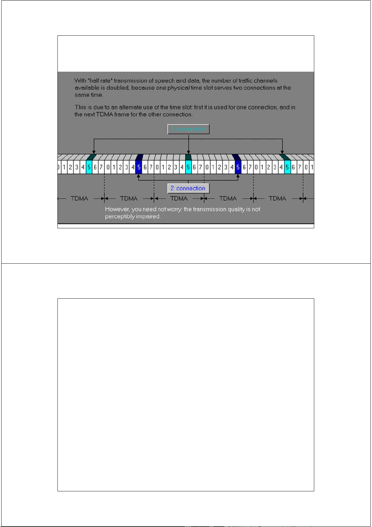
Kết nối bán tốc - Haftrate 55 2/17/2014
Đa khung điều khiển - Control Multiframe MF51
Đa khung không kết hợp(non-combined multiframe).
• Đa khung điều khiển quảng bá
-> BCCH Multilframe: Luôn mang trên TS0 của sóng mang BCCH.
• Đa khung điều khiển chuyên dụng. -> DCCH Multilframe.
Đa khung kết hợp(combined multiframe): kết
hợp hai kiểu đa khung trên. 56 2/17/2014
Đa khung quảng bá - BCCH/CCCH Frame 0 1 2 49 50 DL B C C C C C C C C C 1 block = 4 TS 0 50 UL FCCH SCH RACH Idle BCCH CCCH: PCH or AGCH 57 2/17/2014
Đa khung chuyên dụng - SDCCH/8 1 block = 4 TS Mang CBCH 0 3 50 D0 D1 D2 D3 D4 D5 D6 D7 A A 0 A1 2 A3 DL D0 D1 D2 D3 D4 D5 D6 D7 A A 4 A5 6 A7 51 101 1 block = 4 TS 0 3 50 A5 A6 A7 D0 D1 D2 D3 D4 D D 5 D6 7 A0 UL A1 A2 A3 D0 D1 D2 D3 D4 D D 5 D6 7 A4 51 101 D: SDCCH/8 A: SACCH/8 Idle 58 2/17/2014
Đa khung kết hợp – SDCCH/4 Frame 0 1 2 Mang CBCH 50 DL B C C C D0 D1 D D 2 3 A0 A1 B C C C D4 D5 D6 D7 A2 A3 0 101 D3 A0 A1 D D D 0 1 2 UL D3 A2 A3 D D D 0 1 2 101 FCCH SCH RACH Idle BCCH CCCH: PCH or AGCH SACCH/4 SDCCH/4 59 2/17/2014
Đa khung quảng bá BCCH/CCCH F: FCCH : Frequency T T T T T T T T T T T Correction channel
0 1 2 3 4 5 6 7 … 1 1 ………….. 5 0 1 0
S: SCH : Synchronization channel B: BCCH : Broadcast Frame Control channel number Time
0 1 2 3 4 5 6 7 … 10 1112 ……… 50 slots
The remaining frames 0
F S B B B B C C … F S . . . I
contain : Common
Control Channels (CCCH) 1
and Dedicated Controls 2
Channels (DCCH) in TS0 3
Also FCCH and SCH
appear 5 times in a 4 Multiframe 5 6 7 60 2/17/2014 Cấu trúc đa khung 61 2/17/2014 Cấu hình kênh báo hiệu
Cấu hình cấp phát kênh báo hiệu trong 1 kênh tần số
RFC phụ thuộc vào mật độ thuê bao và lưu lượng báo hiệu.
Đối với 1 cell bình thường (standard cell) sóng mang
BCCH sẽ mang đa khung điều khiển không kết hợp với 8 kênh SDCCH tại TS1 TCH BCCH TS Carrier 0 TS1 TS2 TS3 TS4 TS5 TS6 TS7 C0 BCCH/ SDCCH/8 CCCH
C0:Sóng mang BCCH – sóng mang tham chiếu 62 2/17/2014 Cấu hình kênh báo hiệu
Đối với 1 cell lớn (busier/larger cells – require 4 or
more carrier) sóng mang BCCH sẽ mang đa khung điều
khiển không kết hợp với 16 kênh SDCCH tại TS1 và TS2 TCH BCH ARFCN Sóng mang BCCH TS BCCH 0 TS1 TS2 TS3 TS4 TS5 TS6 TS7 Carrier C0 BCCH/ SDCCH/8 CCCH SDCCH/8 63 2/17/2014 Cấu hình kênh báo hiệu
Đối với 1 cell nhỏ (quite cells in rural area) sóng mang
BCCH sẽ mang đa khung điều khiển kết hợp với 4 kênh SDCCH/4 tại TS0 TCH BCH ARFCN Sóng mang BCCH TS BCCH 0 TS1 TS2 TS3 TS4 TS5 TS6 TS7 Carrier C BCCH/CCCH + SDCCH/4 0 64 2/17/2014
Ánh xạ tổ hợp kênh logic vào kênh vật lý 65 2/17/2014 Chu trình thu phát của MS 66 2/17/2014
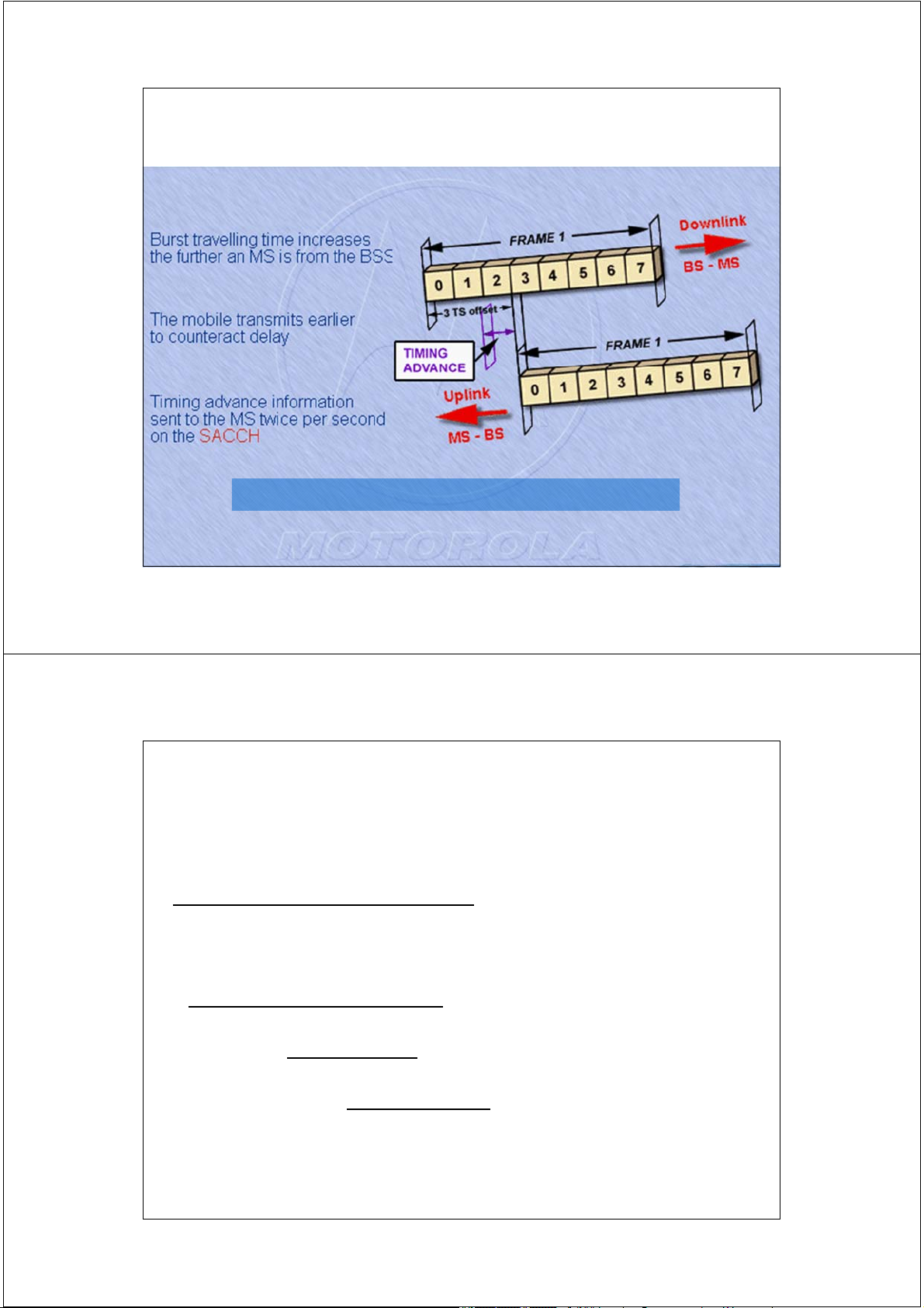
Định thời sớm - timing advance
Bán kính cell 35 km 233 µs 67 2/17/2014
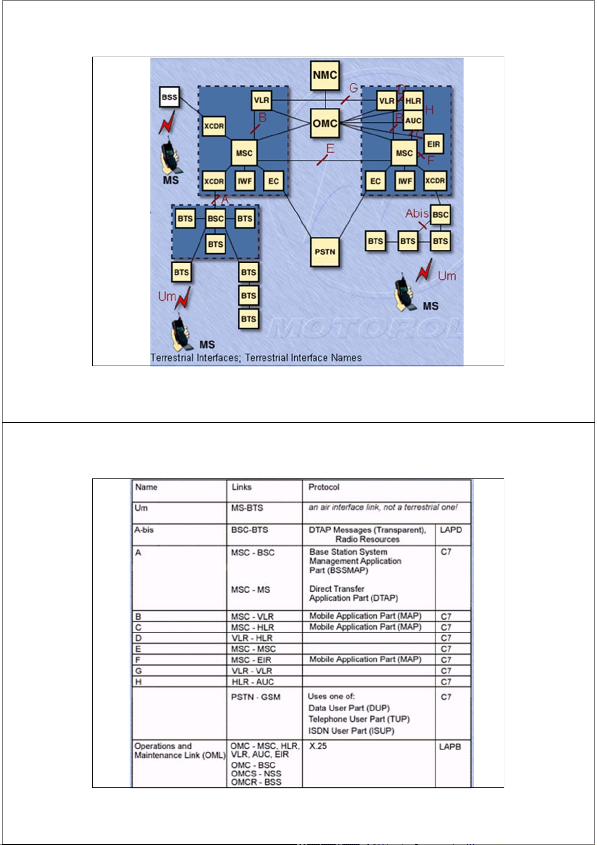
Các giao diện trong mạng GSM Giao diện – Interface:
”Là ranh giới giữa các thực thể chức năng
(functional entities) tại đó khuôn dạng dữ
liệu (protocols) và quá trình trao đổi
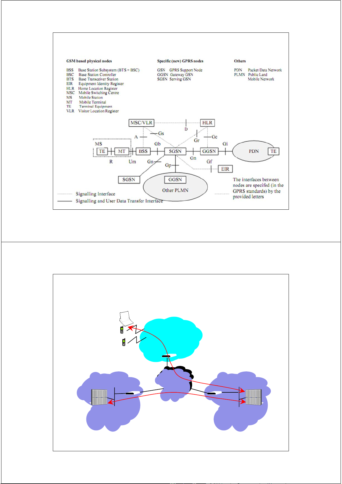
thông tin (procedure) được chuẩn hóa” 68 2/17/2014 69 2/17/2014 70 2/17/2014 Cấu trúc CCS7 71 2/17/2014 Cấu trúc khung LAPD 72 2/17/2014 Báo hiệu CCS7 - MTP 73 2/17/2014 Báo hiệu CCS7 - UP 74 2/17/2014
Trường Đại học Bách Khoa Hà Nội
Khoa Điện tử Viễn thông Thông tin di động Mobile Communications
TS. Đỗ Trọng Tuấn
Bộ môn Kỹ thuật thông tin Hà Nội, 9-2010 1 2/17/2014
Tính toán dung lượng trong mạng GSM ξ1. Một số khái niệm 2 2 2/17/2014 Khái niệm lưu lượng Lưu lượng - traffic:
”Là thông tin (người sử dụng/báo hiệu) mang trên
các kênh truyền dẫn ”
Lưu lượng giờ bận (Busy hour traffic):
“Thời gian chiếm kênh trong giờ bận” A = C*t/T = C*t/3600
[ Erlangs = (Calls/busy hour)*(mean call holding time) ] Trong đó: A: lưu lượng [Erl]
C: số cuộc gọi trong giờ bận
t: thời gian trung bình của một cuộc gọi (s)
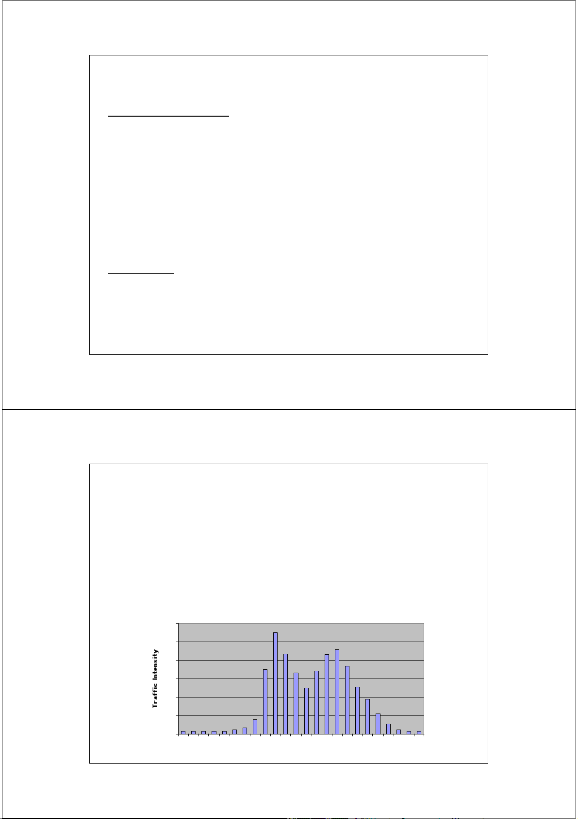
T: thời gian khảo sát = 1h = 3600 s 3 3 2/17/2014 Giờ bận B.H - Busy Hour
B.H là giờ có lưu lượng trao đổi qua các
kênh lớn nhất trong ngày và được xác
định theo số liệu thống kê.
(Busy hour is that continuous 60 minutes time span of
Traffic Intensity over Day
the day during which the highest usage occurs). 120 100 80 60 40 20 0 4 1 2 3 4 5 6 7 8
9 10 11 12 13 14 15 16 17 18 19 20 21 22 23 24 Hour of Day 4 2/17/2014 Ví dụ
Cho biết tải lưu lượng của MS là bao nhiêu khi thuê bao
di động đó tiến hành 2 cuộc gọi trong giờ bận với thời gian trung bình là 90 s.
Tải lưu lượng Lưu lượng giờ bận (Busy hour traffic):
A = C*t/T = C*t/3600 = 2*90/3600 = 50 mErl
Ý nghĩa: thời gian chiếm kênh tại giờ bận của MS là
180 s tương ứng với tải lưu lượng 50 mErl
Thời gian trung bình 1 cuộc gọi của MS trong giờ bận khoảng 50 s ÷ 90 s 5 5 2/17/2014 Traffic Density / Intensity
Mật độ lưu lượng - Traffic Density is defined as the
number of simultaneous calls at a given moment.
Cường độ lưu lượng - Traffic Intensity represents the
average traffic density (occupancy) during any one hour period.
• Chiếm kênh - occupancy is any use of of a traffic resource
regardless of whether or not a connection (call) is completed. 6 6 2/17/2014
Offered, Carried and Blocked Traffic
Lưu lượng yêu cầu Ao - Offered traffic is the traffic
intensity that would occur if all traffic submitted to a
group of circuits could be processed.
Lưu lượng thực hiệnh Ac - Carried traffic is the traffic
intensity actually handled by the group.
Lưu lượng nghẽn Ab - Blocked traffic is that portion of
traffic that cannot be processed by the group of circuits
(I.e. offered traffic minus carried traffic).
• Blocked traffic may be rejected, retried or offered to another 7 group of circuits (overflow). 7 2/17/2014
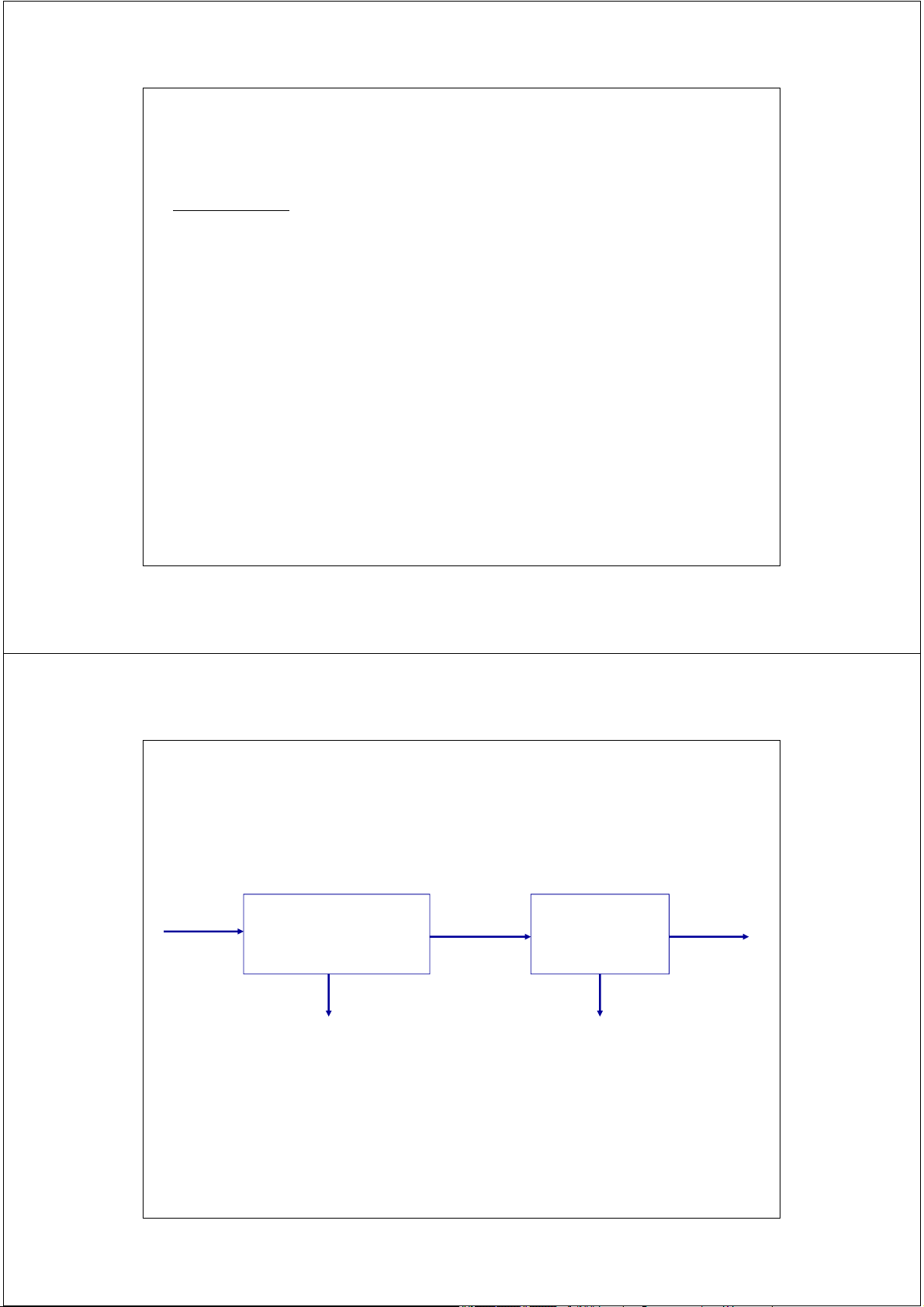
Quan hệ giữa các loại lưu lượng Ao Thiết lập cuộc gọi Ac = A’o Kênh A’c (kênh báo hiệu) lưu lượng A A’ b b Ao = Ac + Ab 8 8 2/17/2014
Cấp dịch vụ GoS (Grade of Service)
Khái niệm: GoS là thông số đánh giá xác suất lưu lượng
nghẽn (Ab) đối với một số kênh xác định: GoS = Ab / Ao
Quan hệ giữa lưu lượng và cấp dịch vụ GoS: Ab = GoS * Ao Ac = (1 - GoS) * Ao
Giá trị GoS điển hình của mạng PLMN = 2%
-> lưu lượng nghẽn = 2% ; lưu lượng thực hiện = 98% 9 9 2/17/2014
Quan hệ giữa lưu lượng và GoS GoS GoS’ Ao Thiết lập cuộc gọi Ac = A’o Kênh A’c (kênh báo hiệu) lưu lượng A A’ b b A’c = f(Ao) = ?
A’c = (1-GoS’)A’o = (1-GoS’)*(1- GoS)*A 10 o 10 2/17/2014 Loss and Delay Systems
Hệ thống tổn thất - A Loss System is one in which a
call attempt is rejected when there is no idle resource
to serve the call. (GSM system)
• Blocked calls…cuộc gọi bị nghẽn
• Resource = signalling channels + traffic channels
Hệ thống trễ - A Delay System is one in which call
attempts are held in a waiting queue until resource are available to serve the calls. • Delayed calls… 11 11 2/17/2014 Mô hình Erlang B
Là mô hình hệ thống thông tin theo kiểu tổn thất.
Mô hình Erlang B được sử dụng để tính
toán dung lượng cho mạng thông tin di động GSM.
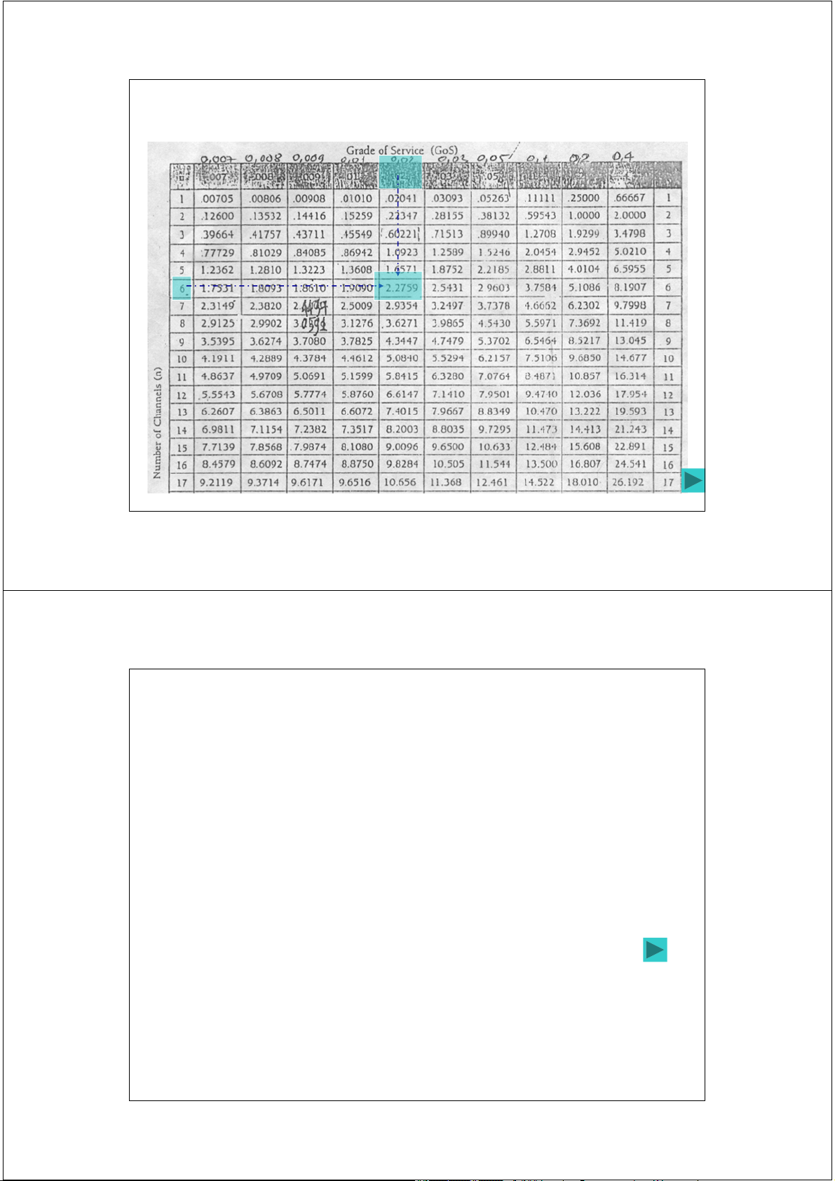
Bảng Erlang B: tra cứu thông số theo mô hình Erlang B
12 * Thể hiện mối quan hệ giữa 3 đại 12 2/17/2014 Bảng Erlang B 13 13 2/17/2014
Hiệu suất sử dụng kênh
Khái niệm: Là tỷ số giữa lưu lượng đáp ứng và số kênh được sử dụng: η = Ac *100/ N (%)
Với ví dụ trên: N = 6, GoS = 2% ; Ac = 2,2304 Erl
η = Ac / N = 2,2304*100/6 = 37% η = ? Khi GoS = 10%
η = Ac / N = 3,3826*100/6 = 56%
Nhận xét: Hiệu suất sử dụng kênh thấp -> xác suất
nghẽn nhỏ -> GoS nhỏ -> chất lượng tốt. 14 14 2/17/2014
ξ2. Tính toán vùng phủ sóng 15 15 2/17/2014 Bài toán
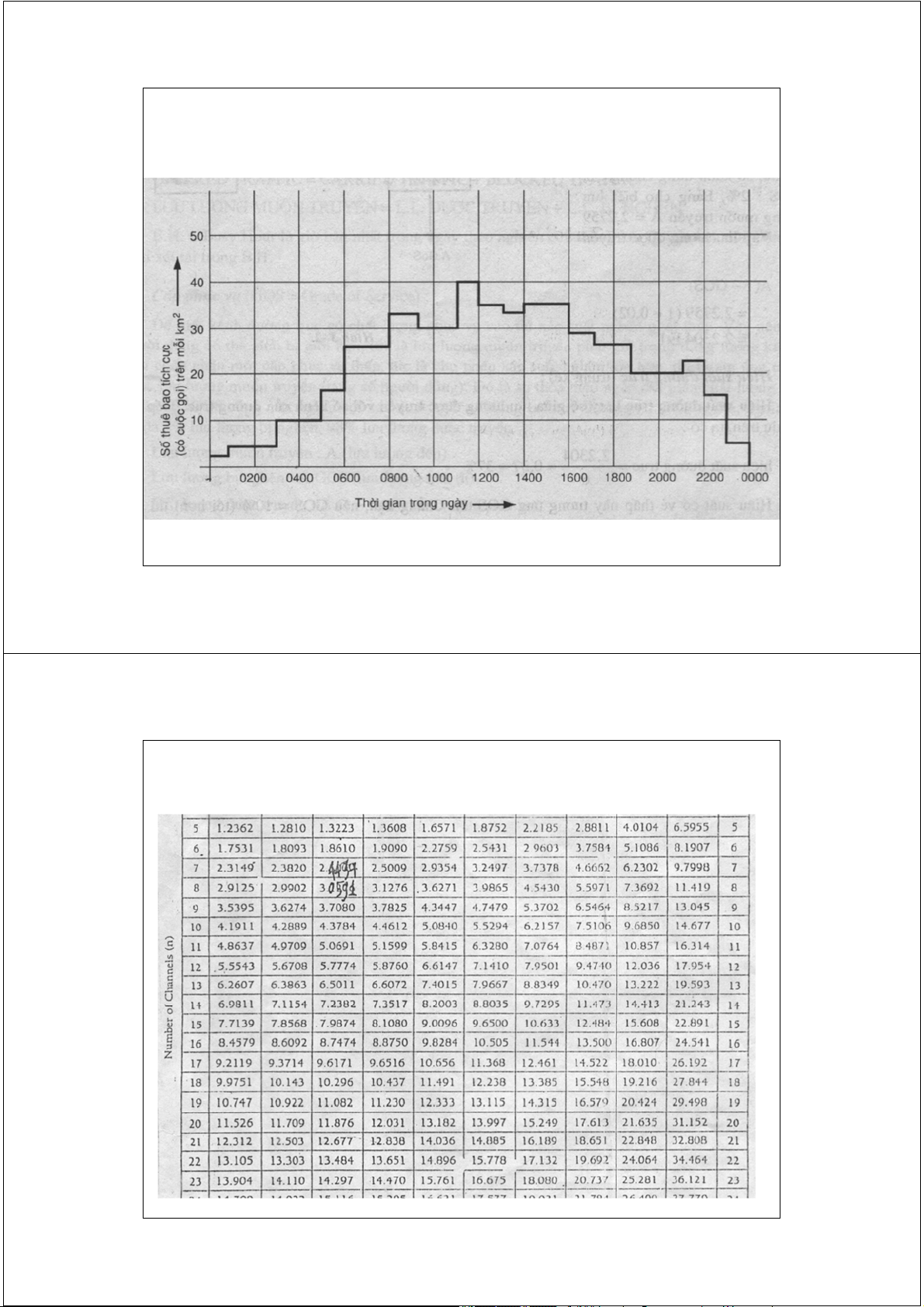
Cần quy hoạch vùng phủ sóng cho thị trấn C, sử dụng công nghệ
GSM900, dùng 3 cặp tần số cho mỗi cell với cấu hình cấp phát
kênh báo hiệu chuẩn. Yêu cầu GoS = 2% với mức lưu lượng dự
đoán được thể hiện như hình vẽ. Giả thiết mỗi thuê bao tiền hành
2 cuộc gọi trong giờ bận với thời gian trung bình của một cuộc gọi là 90 s. [*] Hãy xác định: -
Lưu lượng giờ bận dự kiến trên 1 km2 - Dung lượng của 1 cell. -
Bán kính cực đại của cell (diện tích cell hình lục giác S = 2,6 R2) -
Số cell cần thiết để phủ sóng cho cả thị trấn C. 16 -
Lặp lại các phép tính trên khi cấp phát 4 tần số cho mỗi cell. 16 2/17/2014
Mức lưu lượng dự đoán ở thị trấn C 17 17 2/17/2014 Bảng Erlang B 18 18 2/17/2014 19 2/17/2014 20 2/17/2014 21 2/17/2014 22 2/17/2014 23 2/17/2014 24 2/17/2014
Trường Đại học Bách Khoa Hà Nội
Khoa Điện tử Viễn thông Thông tin di động Mobile Communications
TS. Đỗ Trọng Tuấn
Bộ môn Kỹ thuật thông tin Hà Nội, 9-2010 1 2/17/2014
General Packet Radio Service (GPRS) 2 2 2/17/2014
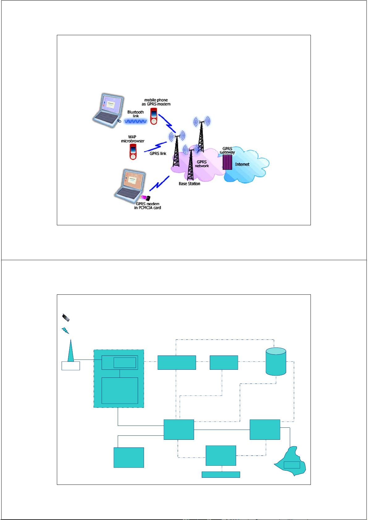
General Packet Radio Service (GPRS) 3 3 2/17/2014 GPRS Network Architecture RF air interface BSC MSC/VLR SMSC HLR BTS Packet Control Unit (PCU) SGSN GGSN Charging SGSN Gateway Function PDN Billing 4 2/17/2014
GPRS system architecture 5 5 2/17/2014
How is GPRS seen by external networks and GPRS users? HOST 155.222.33.55 GPRS SUBNETWORK SUBNETWORK 155.222.33.XXX "Router" SUBNETWORK SUBNETWORK 131.44.15.XXX 191.200.44.XXX Packet Corporate 2 Corporate 1 Data Router network Router network (Internet) Local Local area HOST area HOST network 191.200.44.21 network 131.44.15.3 6 2/17/2014 Salient Features of GPRS
Important step on the path to 3G Standardized by ETSI
GPRS is an overlay network over the GSM
Provides Data Packet delivery service
Support for leading internet communication protocols
Billing based on volume of data transferred
Utilizes existing GSM authentication and privacy procedures. 7 2/17/2014 Advantage of GPRS
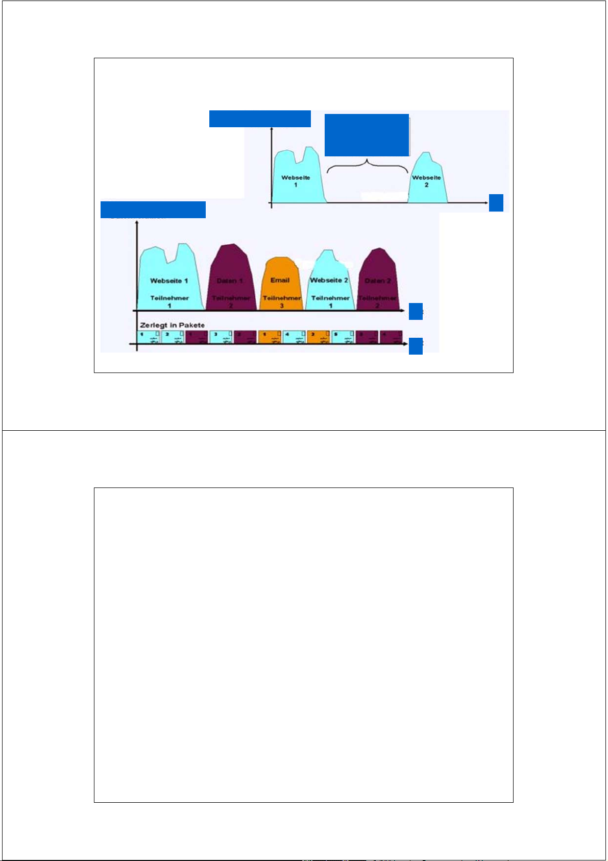
Use of packet-switching technology
Enables multiple users to share air interface resources
Users feel their services to be “always on”
GPRS is primarily for data communication and not for voice communication.
GPRS communicates using TCP/IP protocol similar to the internet. 8 2/17/2014 GPRS Tốc độ truy nhập Không truy nhập t Tốc độ truy nhập t t 9 2/17/2014 Applications
Standard data network protocol based IP based applications • WWW, FTP, Telnet, ...
• Any conventional TCP/IP based applications X.25 based applications
• Packet Assembly/Disassembly (PAD) type approach
GPRS specific protocol based Point-to-point applications
• Toll road system, UIC train control system
Point-to-multipoint applications
• Weather info, road traffic info, news, fleet management
SMS delivery (GPRS as a bearer for SMS) 10 2/17/2014
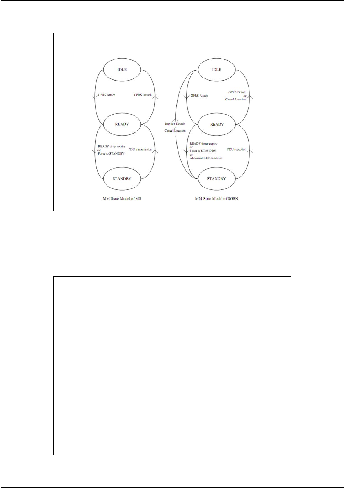
Mobility Management state model in GPRS 11 2/17/2014 QoS Profile for GPRS Bearers
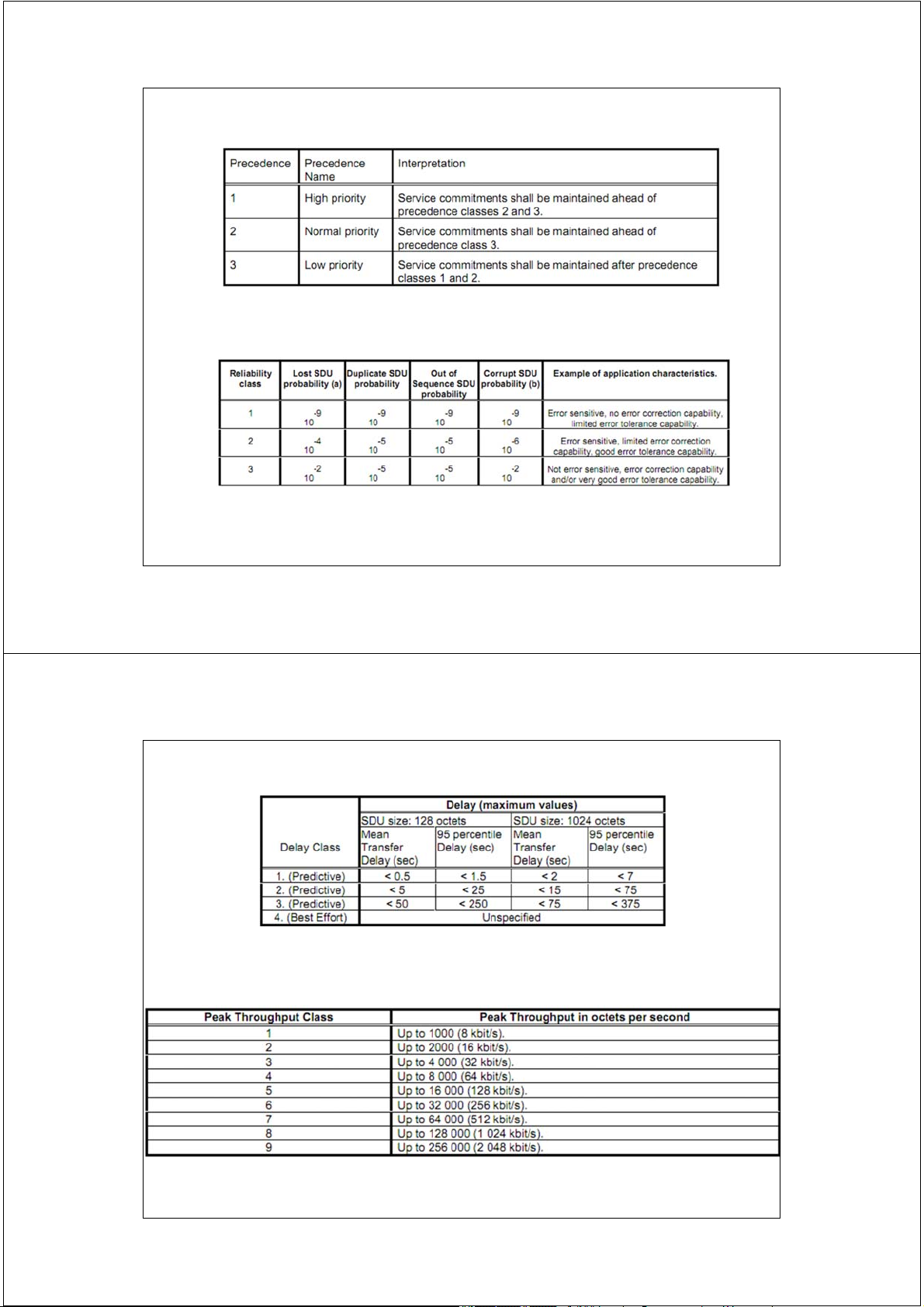
Describes applications characteristics and QoS requirements 4 parameters: • Service precedence 3 classes
• Reliability parameter 3 classes • Delay parameters 4 classes
• Throughput parameter Maximum and mean bit rates 12 2/17/2014
QoS Precedence classes (from [GSM 03.60])
Reliability classes (from [GSM 02.60]) SDU (Service Data Unit) 13 2/17/2014
Delay classes (from [GSM 02.60])
Peak throughput classes (from [GSM 03.60]) 14 2/17/2014
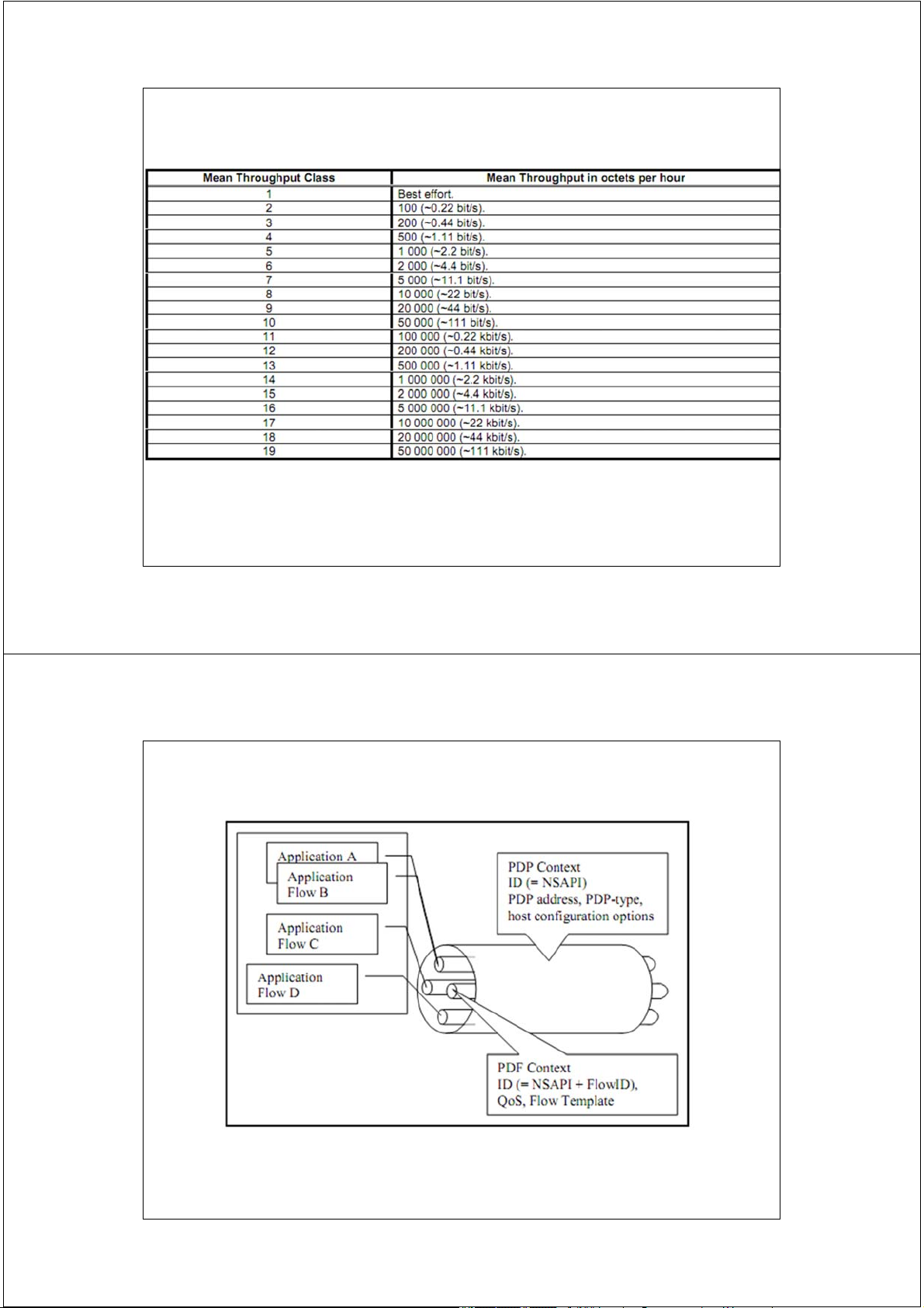
Mean throughput classes (from [GSM 03.60]) 15 2/17/2014 PDP and PDF contexts PDP : Packet Data Protocol PDF : Packet Data Flow
NSAPI : Network layer Service Access Point Identifier 16 2/17/2014
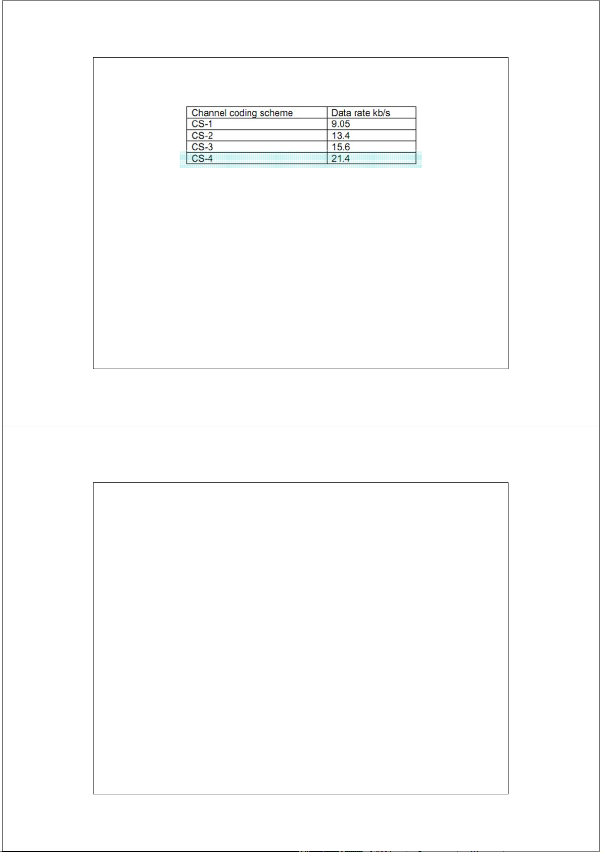
Channel coding schemes applied per time slot
• The Packet Data Traffic Channels (PDTCHs) use four different channel
coding schemes, described in [GSM 04.60] to transfer the packet data
traffic. Above table lists the used channel coding schemes and the data
rates that can be obtained by using these coding schemes per time slot.
• The maximum data rate that can be obtained on PDTCH channels is 8*21.4 kb/s = 171.2 kb/s
i.e., (8 time slots) * (Maximum data rate for CS-4 for a time slot). 17 2/17/2014 PDP Context
PDP: Packet Data Protocol (PDP) is a network protocol
used by an external packet data network interfacing to GPRS.
PDP Context: Information sets held in MS and GSNs for a PDP address
NSAPI: Network Service Access Point Identifier. An
integer value in the range [0; 15], identifying a certain PDP Context. 18 2/17/2014
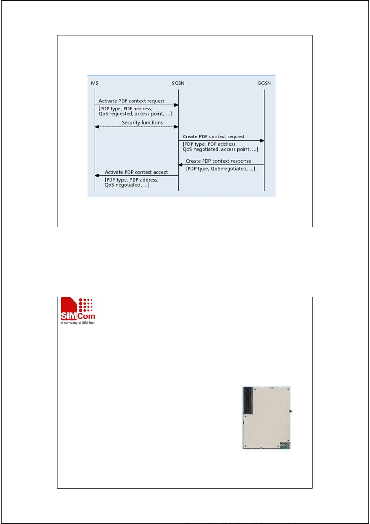
PDP Context Activation Procedure + IP assignment + Roaming 19 2/17/2014 SIM300 Features
Tri or Quad-Band GSM/GPRS
40x33x2.85mm 60-pin ENTERY board to board connector Support sleep mode(about 3mA) Embeded TCP/IP protocol Autobauding Support RTC function
Over-temperature automatic shutdown Operation temperature -20~55Ԩ Supply voltage 3.4-4.5V Support FAX and USSD 20 20 2/17/2014 SIM508 and SIM548 Features
Tri or quad-band GSM/GPRS+GPS 80PIN CONNECTOR GSM part based on SIM300C
GPS receiver with SiRFstar III GSC3f chip set Processor type ARM7/TDMI Software version: SiRF GSW3 Two serial GPS interfaces
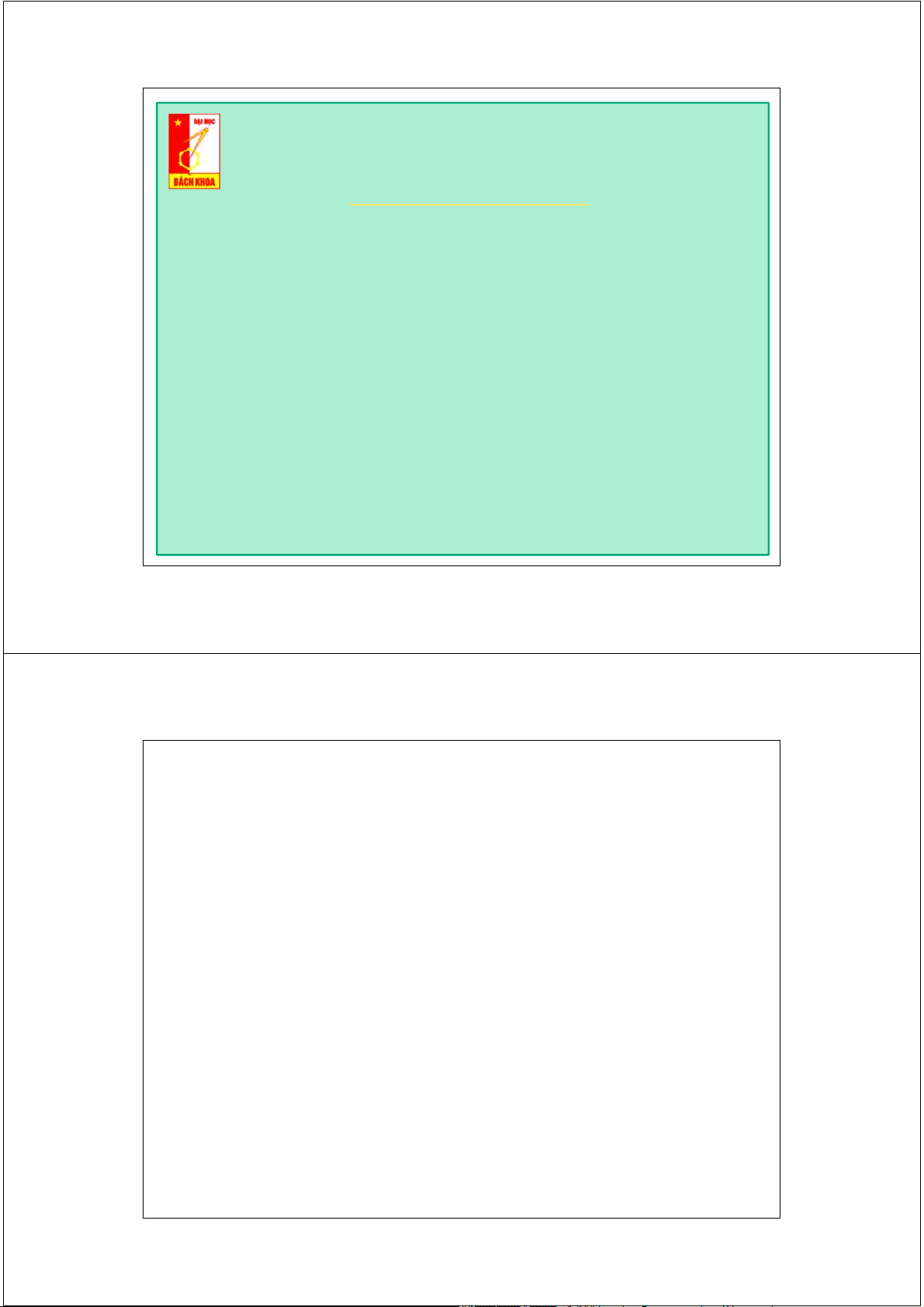
Size: 55±0.15 x 34±0.15 x 2.9±0.3 mm 21 21 2/17/2014 SIM508 and SIM548 Application
PND (Personal Navigation Device)
AVL (Auto Vehicle Location) Tracing 22 22
Trường Đại học Bách Khoa Hà Nội
Khoa Điện tử Viễn thông Thông tin di động Mobile Communications
TS. Đỗ Trọng Tuấn
Bộ môn Kỹ thuật thông tin Hà Nội, 9-2010 1
Mạng thông tin di động 3G UMTS / W-CDMA
(Universal Mobile Telecommunications System)
ξ 1. Khái quát về UMTS 2 2 Rel.99, Rel.4
IMT-2000 : ITU’s umbrella name for 3G which stands for International
Mobile Telecommunications 2000
IMT-DS Direct Spread CDMA: W-CDMA / UMTS New from 3GPP; UTRAN FDD 3 3 WCDMA Background and Evolution 3GPP Rel -99 3GPP Rel 4 3GPP Rel 5 3GPP Rel 6 3GPP Rel 7 Further 12/99 03/01 03/02 2H/04 06/07 Releases 2000 2001 2002 2003 2004 2005 2006 2007 Europe HSDPA Japan HSUPA (pre- Europe (commercial) (commercial) commercial) (commercial) 4
UMTS general characteristics
Multimedia Service & high data rates: WCDMA radio access Environment Max Bitrate Max Speed Cel Size Rural outdoor 144 Kbps 500 Km/h Macro Suburban outdoor 384 Kbps 120 Km/h Macro/Micro Support of QoS mechanisms Indoor 2.048 Mbps 10 Km/h Micro/Pico
Volume-based pricing scheme
Service flexibility, wide bit-rate range and granularity:
Packet- and Circuit- oriented services,
“always on” connectivity, multiple services on one connection,
Additional requirements:
Dual- mode/ coexistence with GSM & inter-system Hand Off,
Channel characteristics negotiation. 5 5
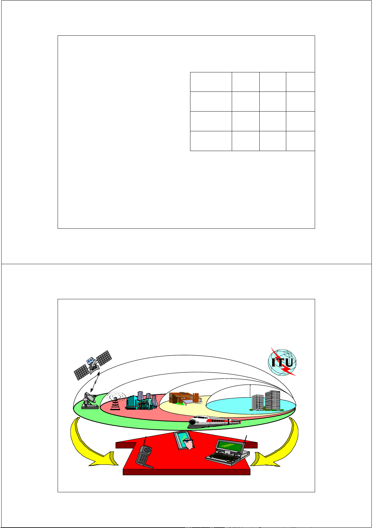
IMT-2000 Vision Includes
LAN, WAN and Satellite Services Global Satellite Suburban Urban In-Building Microcell Picocell Macrocell Basic Terminal PDA Terminal Audio/Visual Terminal 6 UMTS Characteristics
UMTS FDD (Frequency Division Duplex) Uplink: 1920 - 1980 MHz Downlink: 2110 - 2170 MHz 190 MHz duplex distance
5MHz (variable) carrier spacing
12 bands in Uplink & Downlink 12 Uplink 12 Downlink Bands Bands … … 190 MHz 5 MHz Frequency 7 7
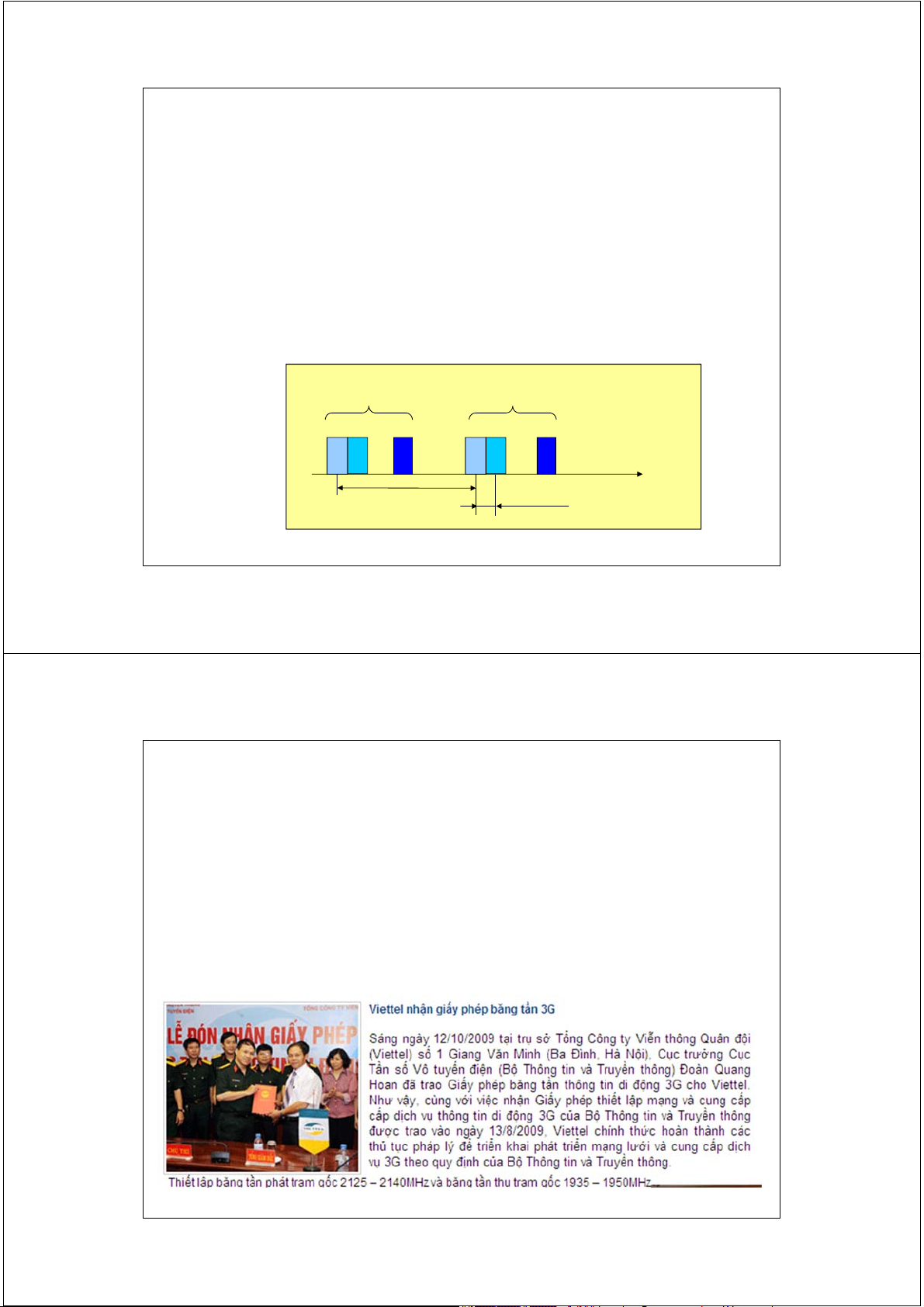
Ngày 16/4/2008, Bộ TT&TT đã ban hành Quyết định số
25/2008/QĐ-BTTTT về việc phê duyệt Quy hoạch băng tần cho
các hệ thống thông tin di động tế bào số của Việt Nam trong
các dải tần 821 ÷ 960 MHz và 1710 ÷ 2200 MHz. Theo Quyết
định này, các đoạn băng tần 1900 ÷ 1980 MHz, 2010 ÷ 2025
MHz và 2110 ÷ 2170 MHz được dành cho hệ thống IMT–2000.
Hiện 4 giấy phép 3G được ấn định 3 kênh tần số cho hướng
xuống (trong dải 2110 ÷ 2170 MHz) và 3 kênh tần số cho
hướng lên (trong dải 1920 ÷ 1980 MHz). 8 8 UMTS Specifications Duplex method: FDD
Channel spacing: 5 MHz
Carrier chip rate: 3.84 Mcps
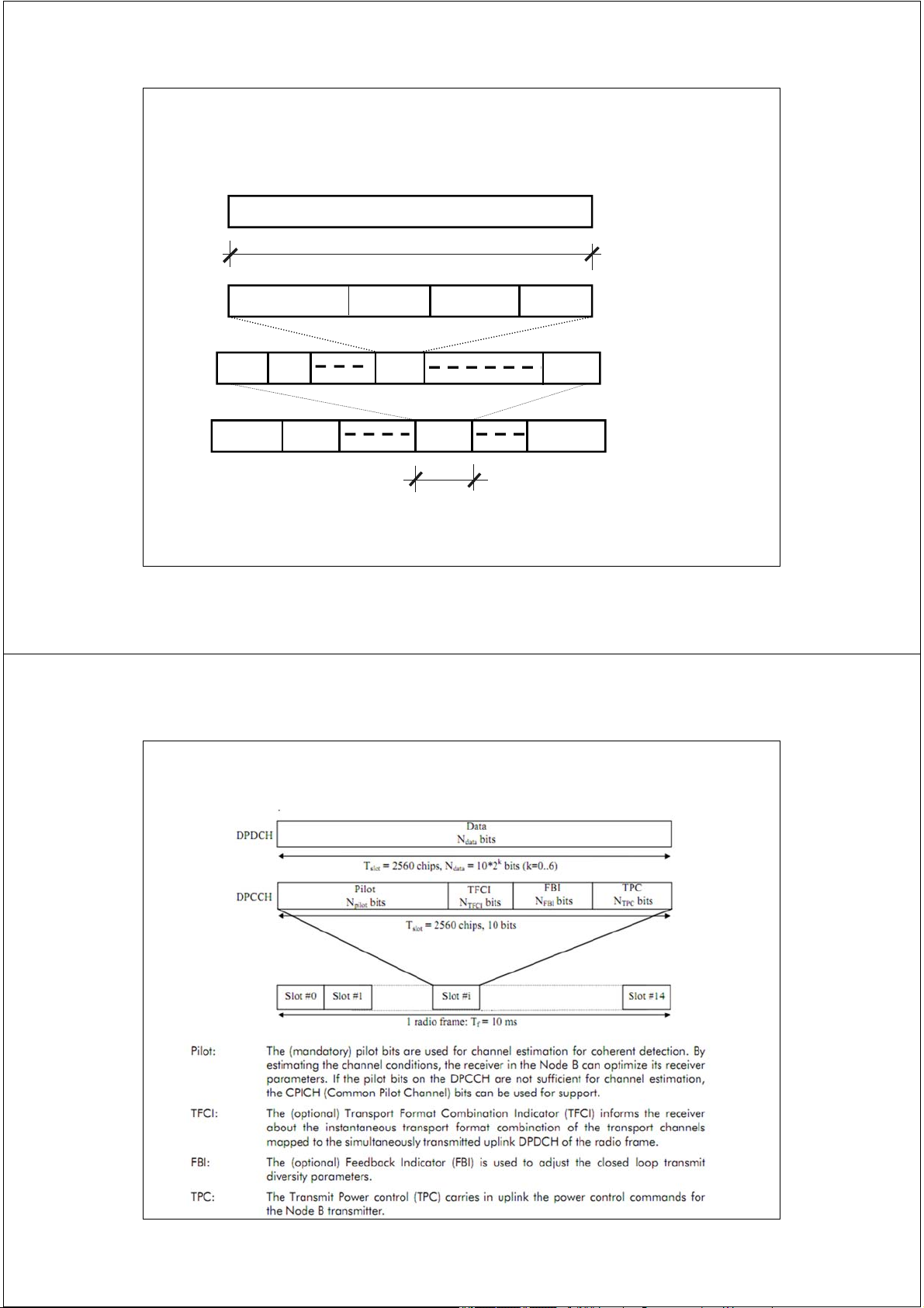
Timeslot structure: 15 slots/frame Framelength: 10 ms Modulation: QPSK
Detection: based on pilot symbols
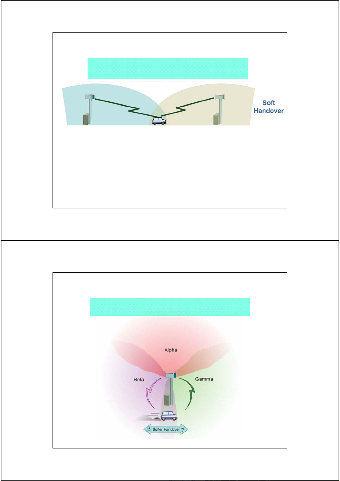
Intra-frequencyHandover: soft
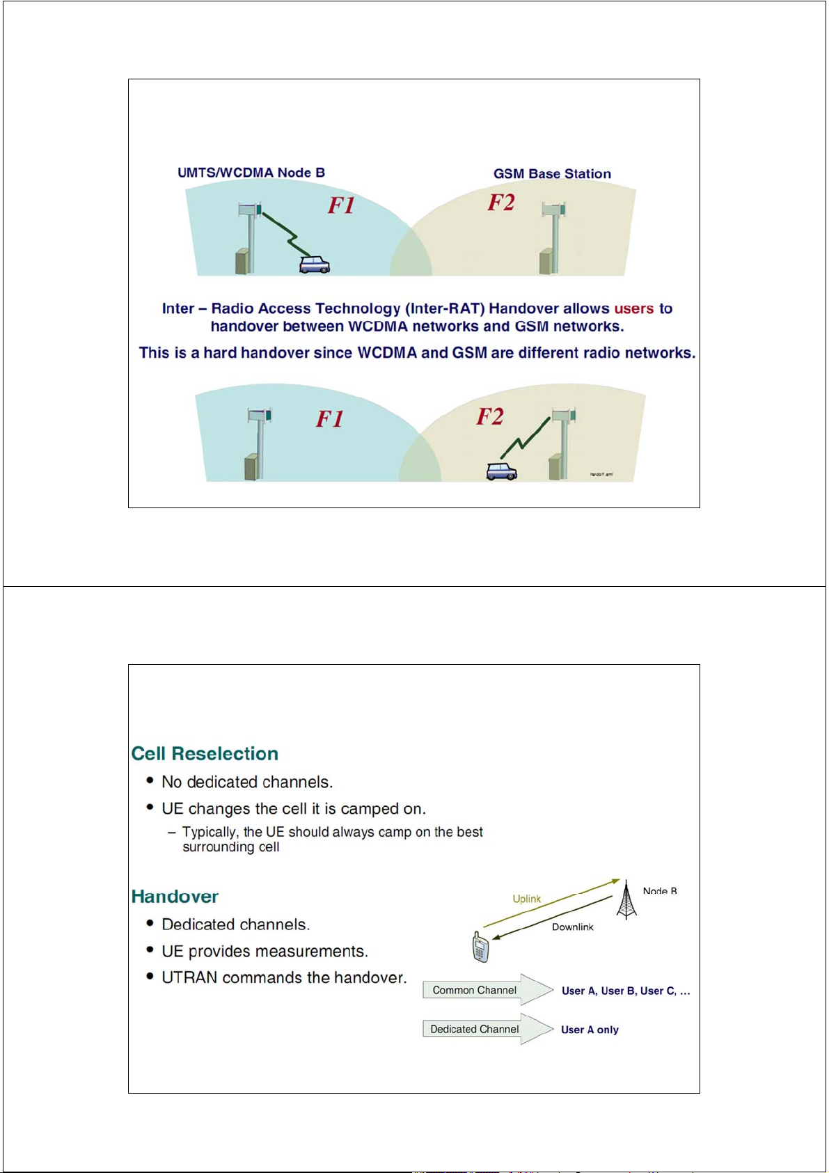
Inter-frequencyHandover: hard
Spreading Factors: 4, 8, 16, 32, 64, 128, 256, 512 9 9
UMTS Network Architecture 10 10
UMTS Network Architecture 11 11
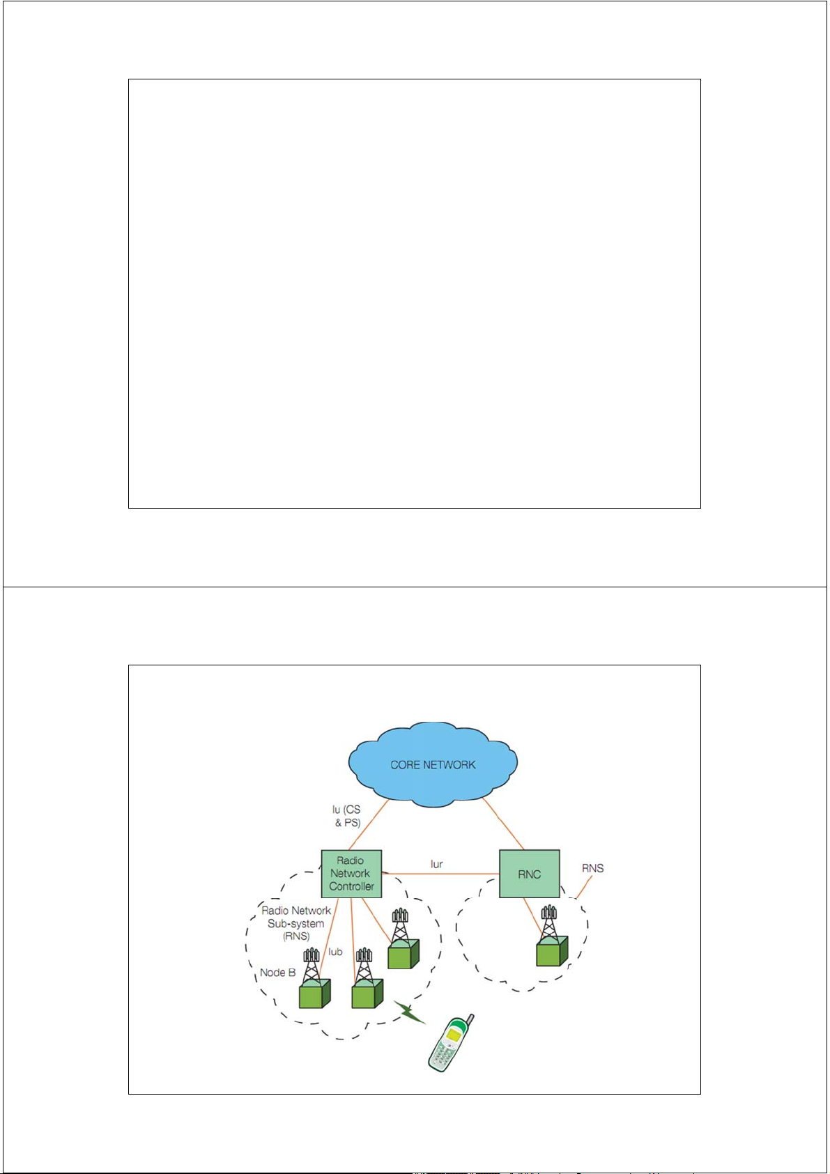
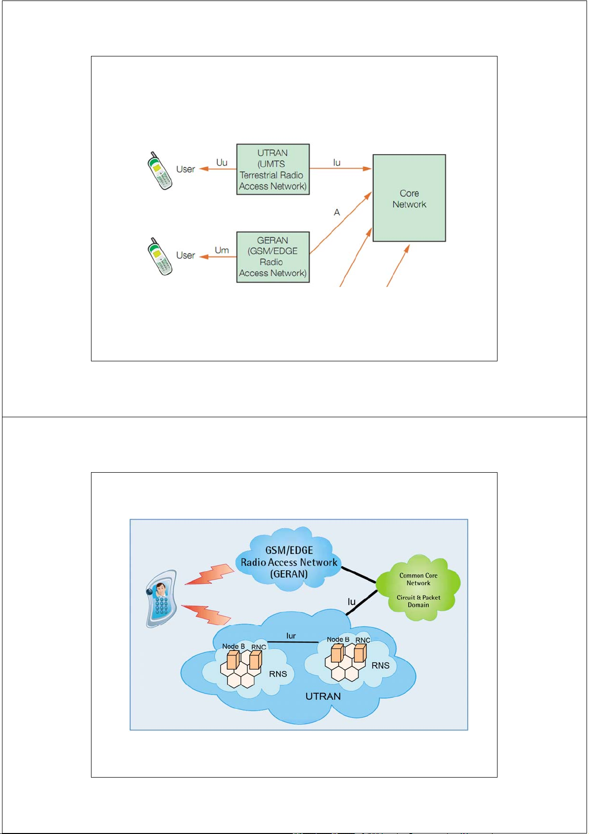
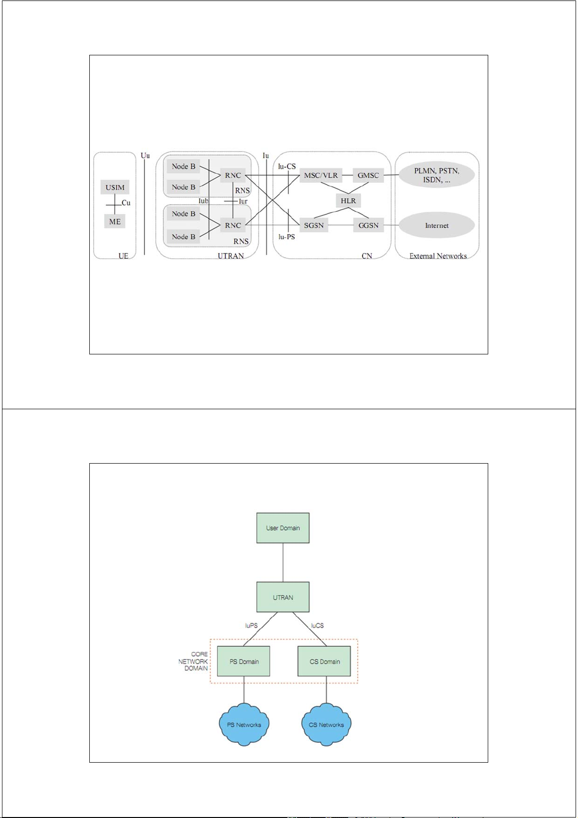
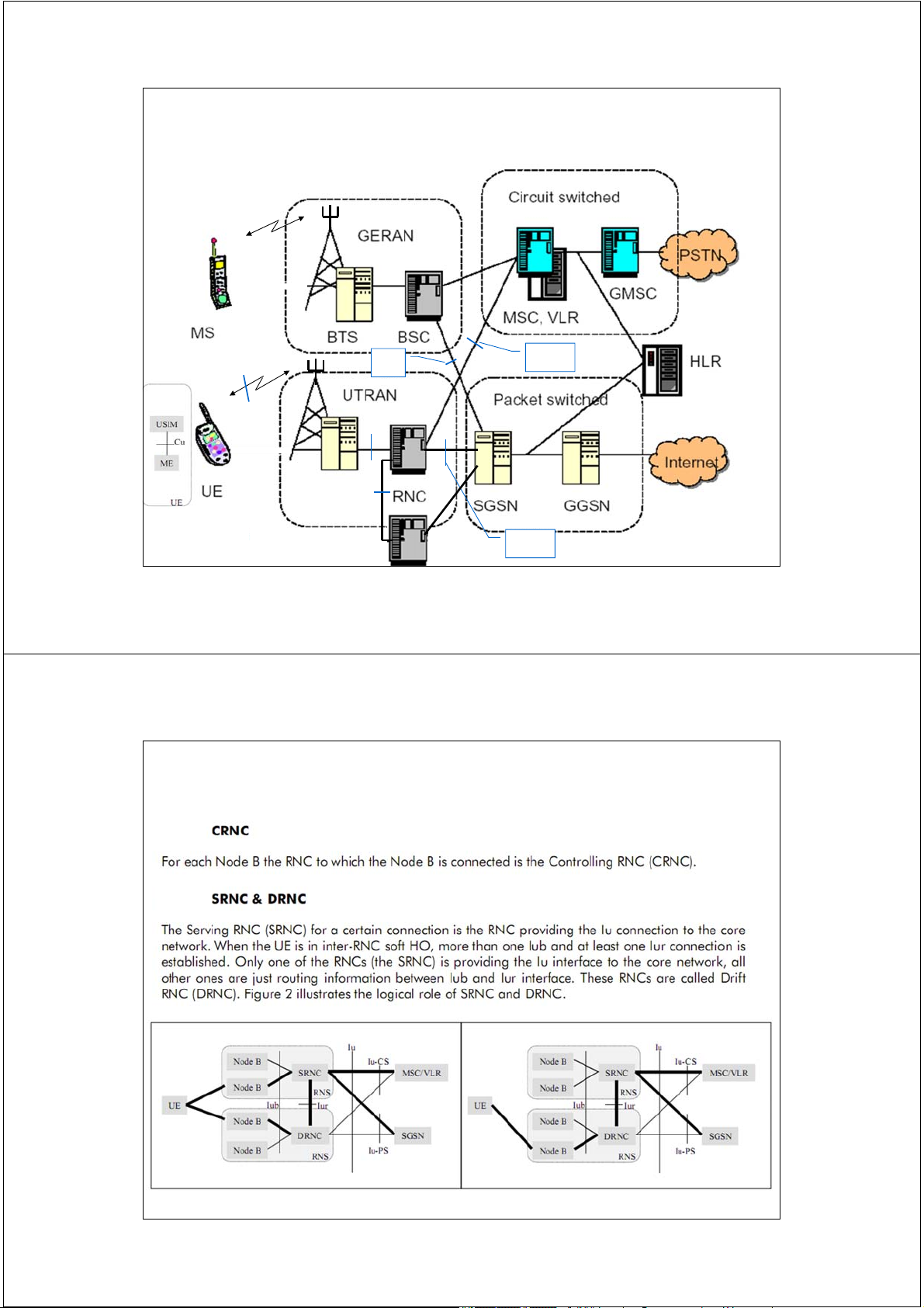
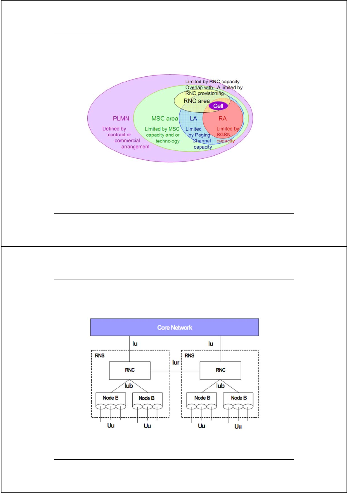
UMTS Network Architecture
RNS: Radio Network Subsystems UTRAN: UMTS Radio Access Network
GERAN: GSM /GPRS/ Edge Radio Access Network 12 12
UMTS Network Architecture Rel.99 13
UMTS Network Architecture Rel.99 14
UMTS Network Architecture Rel.99
GERAN - GSM /GPRS/ Edge Radio Access Network I G u-CS b U I u ub NodeB Iur Iu-PS 15 15 Logical Roles of RNC 16 Logical Roles of RNC
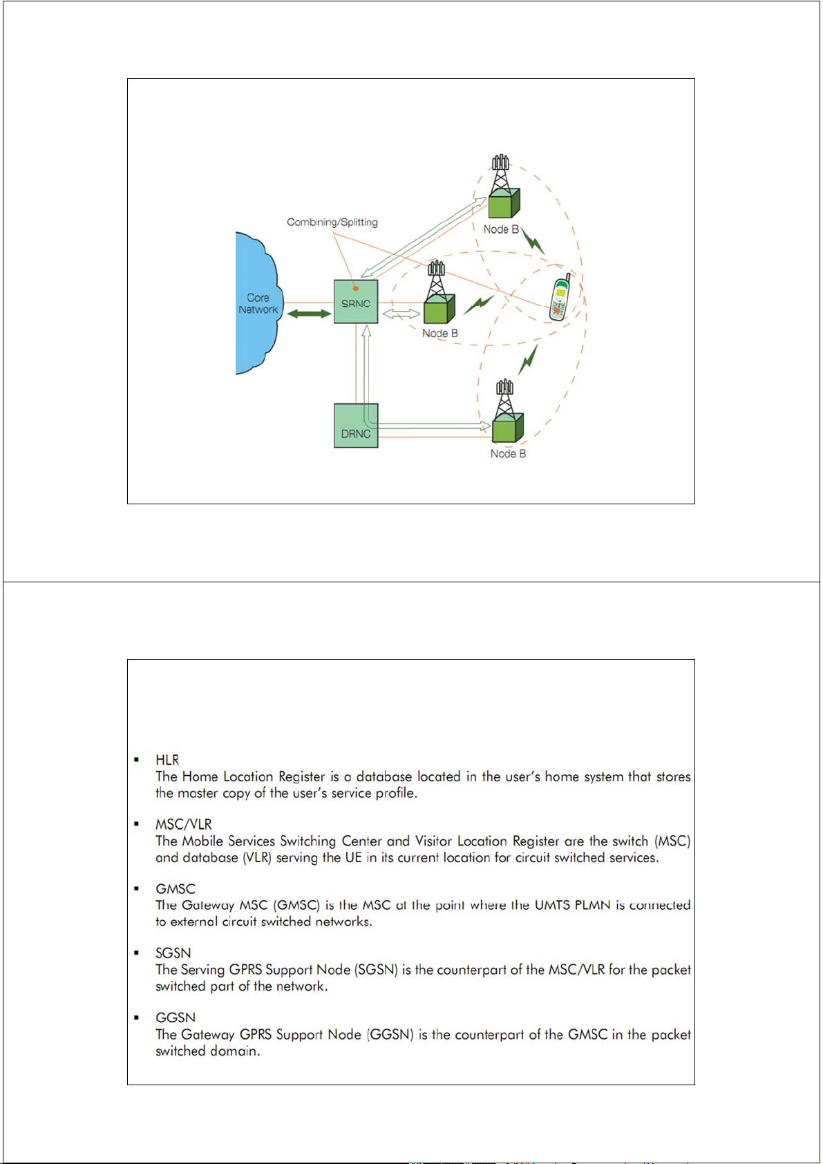
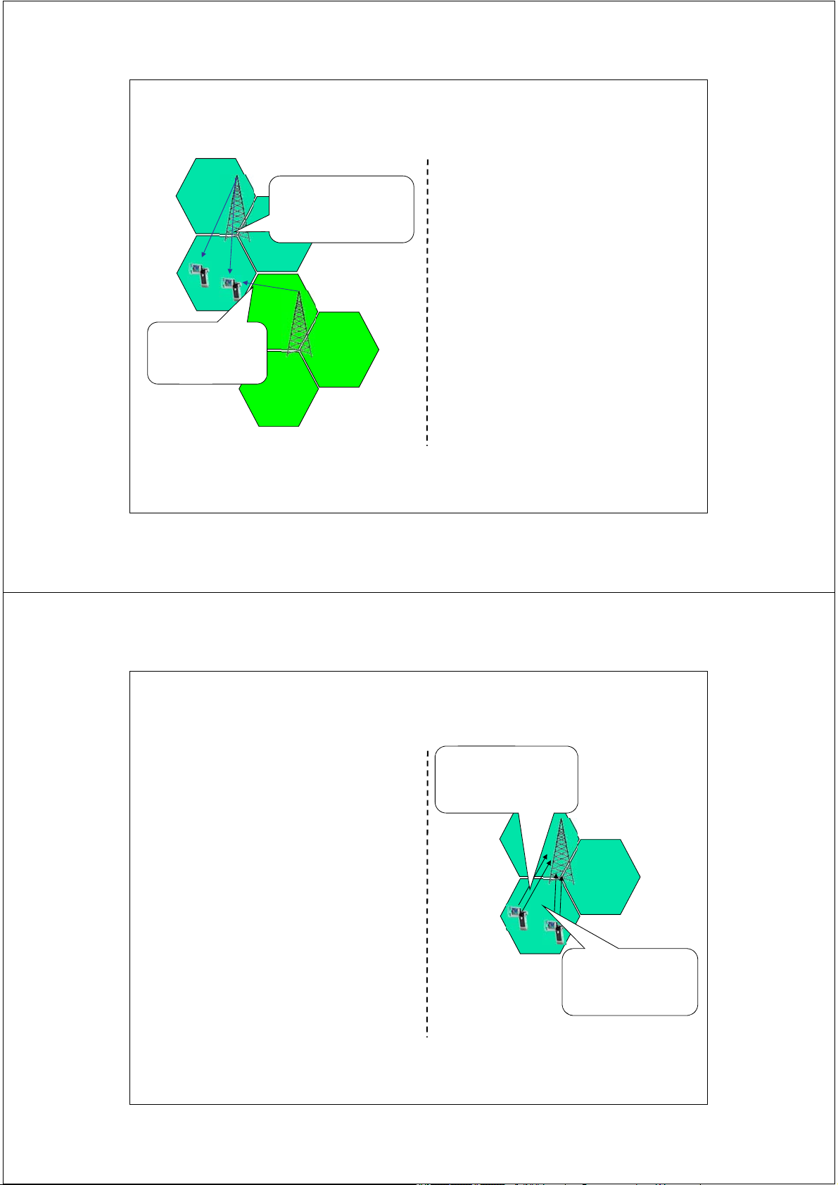
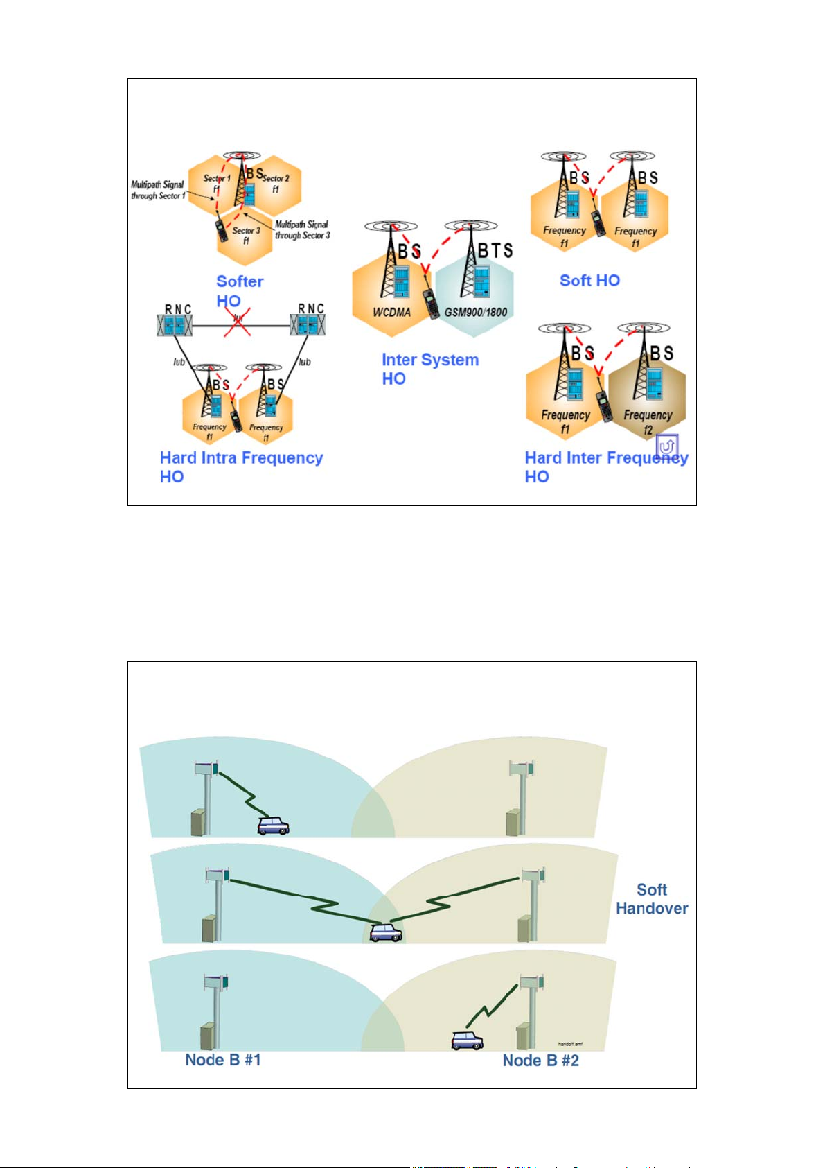
Soft Handover (Macro Diversity) 17
UMTS Network Architecture Rel.99 CN - Core Network 18 Interfaces 19 UTRAN Architecture Uu interface Iub interface RNC UE NodeB CN Iur interface NodeB UE RNC NodeB UTRAN
UTRAN: UMTS Terrestrial Radio Access Network 20 UTRAN Architecture New Radio Access network Uu interface I
needed mainly due to new radio ub interface access technology Core Network (CN) is based on RNC GSM/GPRS UE NodeB CN
Radio Network Controller (RNC) I
corresponds roughly to the Base ur interface NodeB
Station Controller (BSC) in GSM UE RNC Node B corresponds roughly to NodeB the Base Station in GSM UTRAN
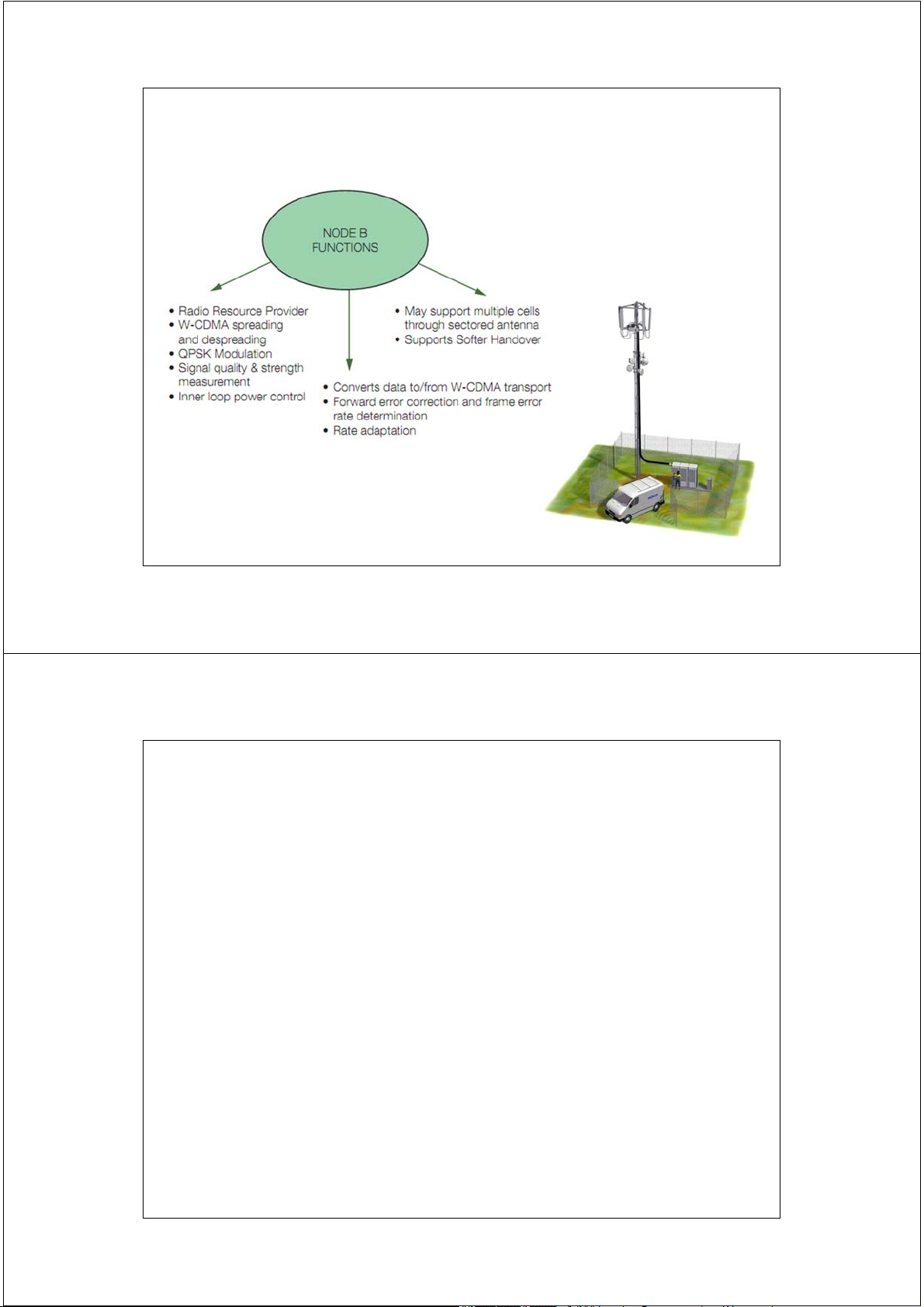
UTRAN: UMTS Terrestrial Radio Access Network 21 UTRAN Architecture Node B
Main function to convert the data flow between Uu and Iub interfaces
Some Radio Resource Management (RRM) tasks: Measurements Innerloop power control 22 UTRAN Architecture 23 UTRAN Architecture
RNC – Radio Node Controller
Controls the radio resources in its domain
Radio Resource Management (RRM) tasks include e.g. the following
Mapping of QoS Parameters into the air interface Air interface scheduling Handover control Outer loop power control Admission Control
Initial power and SIR setting Radio resource reservation Code allocation Load Control 24 UE Class
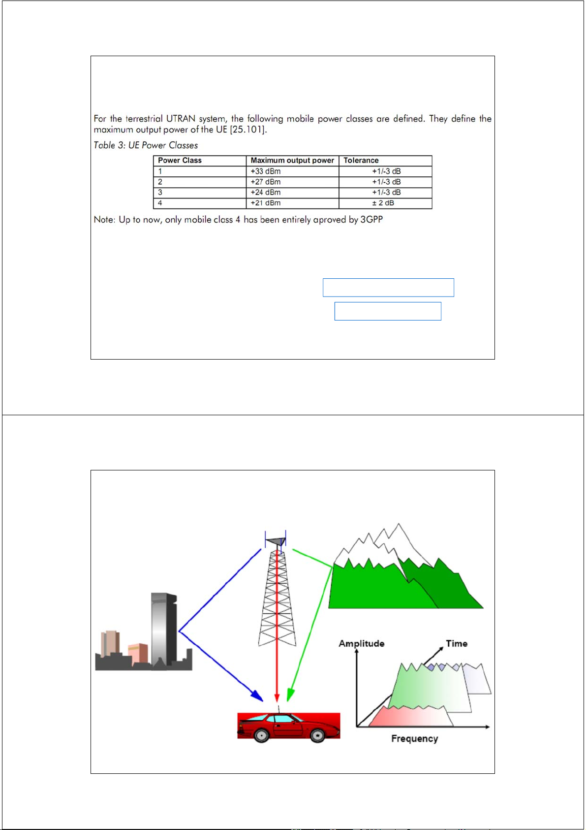
- Độ nhạy thu: là công suất thu tối thiểu sao cho BER không vượt quá một giá trị
tiền định (BER ≤ 0.001): + UE: S = - 117 dBm UE: User Equipement + BTS : S = - 121 dBm. UE = ME + USIM 25 25 Rake Receiver 26 27 28 Rake Receiver 29
Trường Đại học Bách Khoa Hà Nội
Khoa Điện tử Viễn thông Thông tin di động Mobile Communications
TS. Đỗ Trọng Tuấn
Bộ môn Kỹ thuật thông tin Hà Nội, 10-2010 1
Mạng thông tin di động 3G UMTS / W-CDMA
(Universal Mobile Telecommunications System)
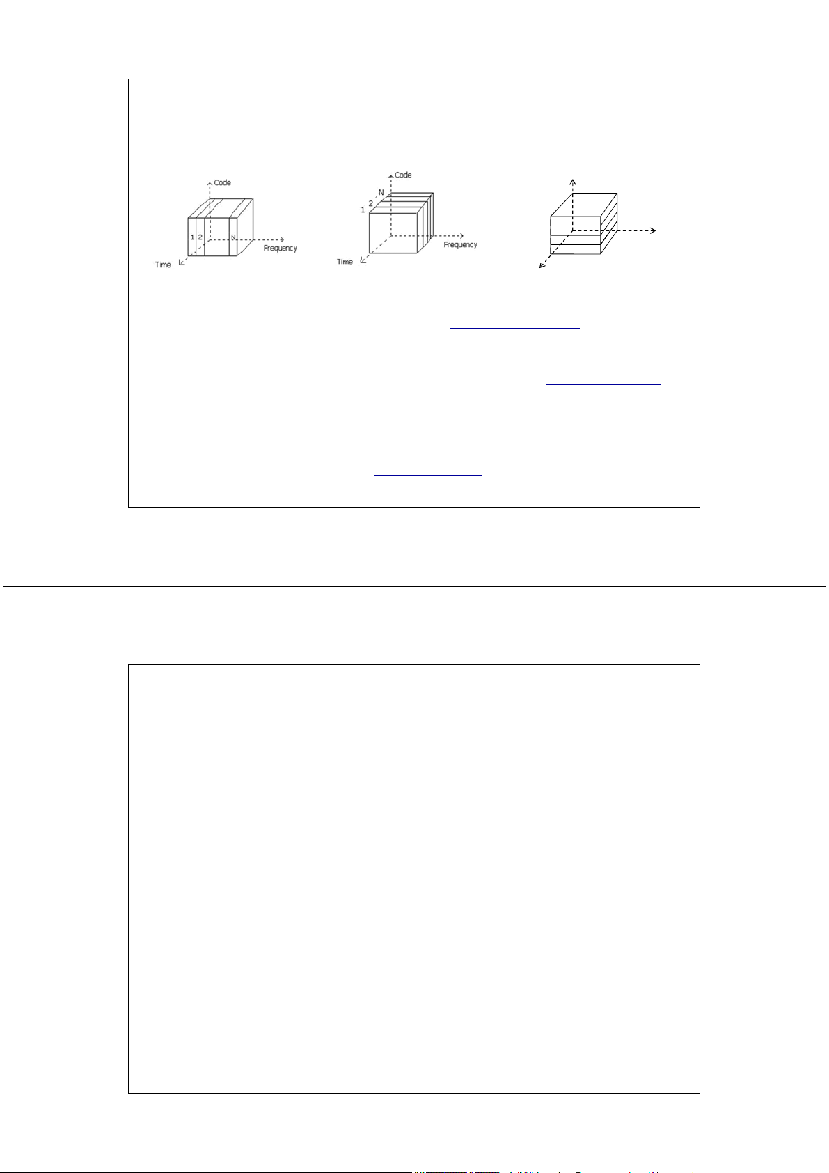
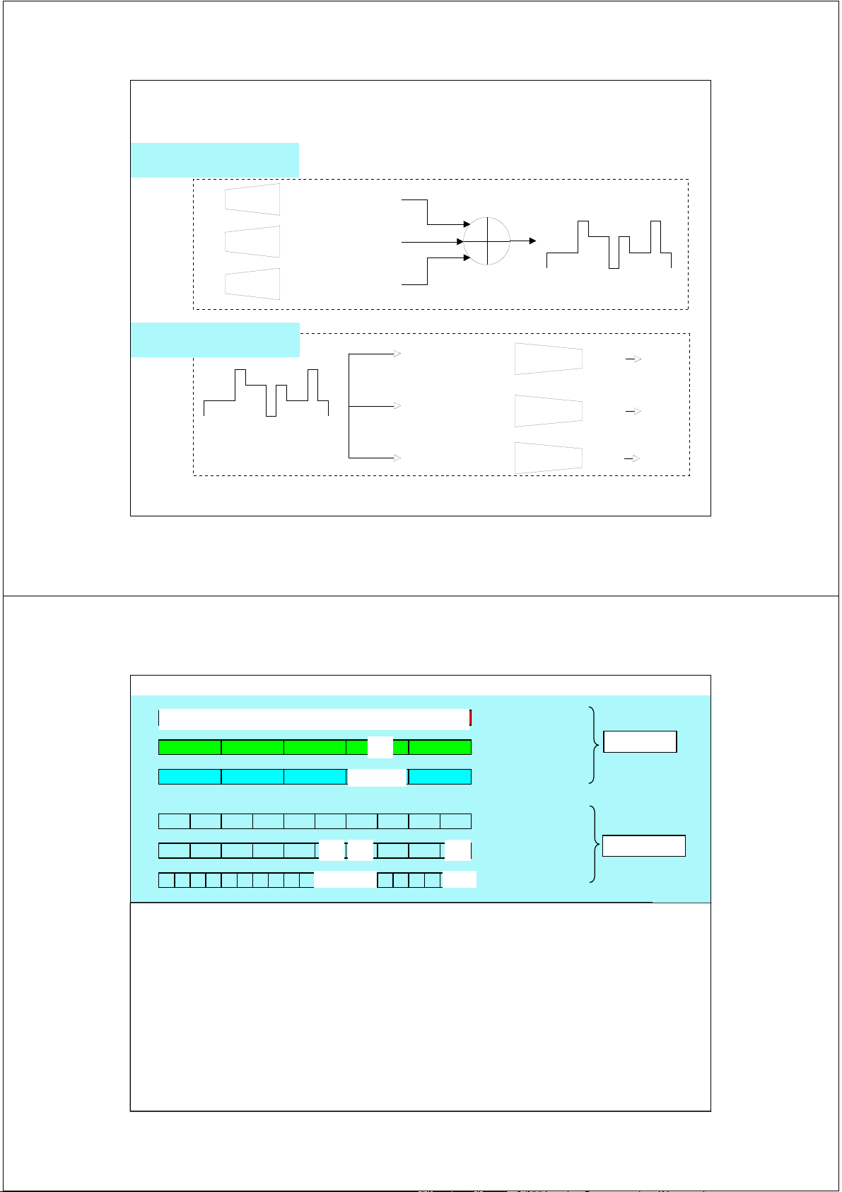
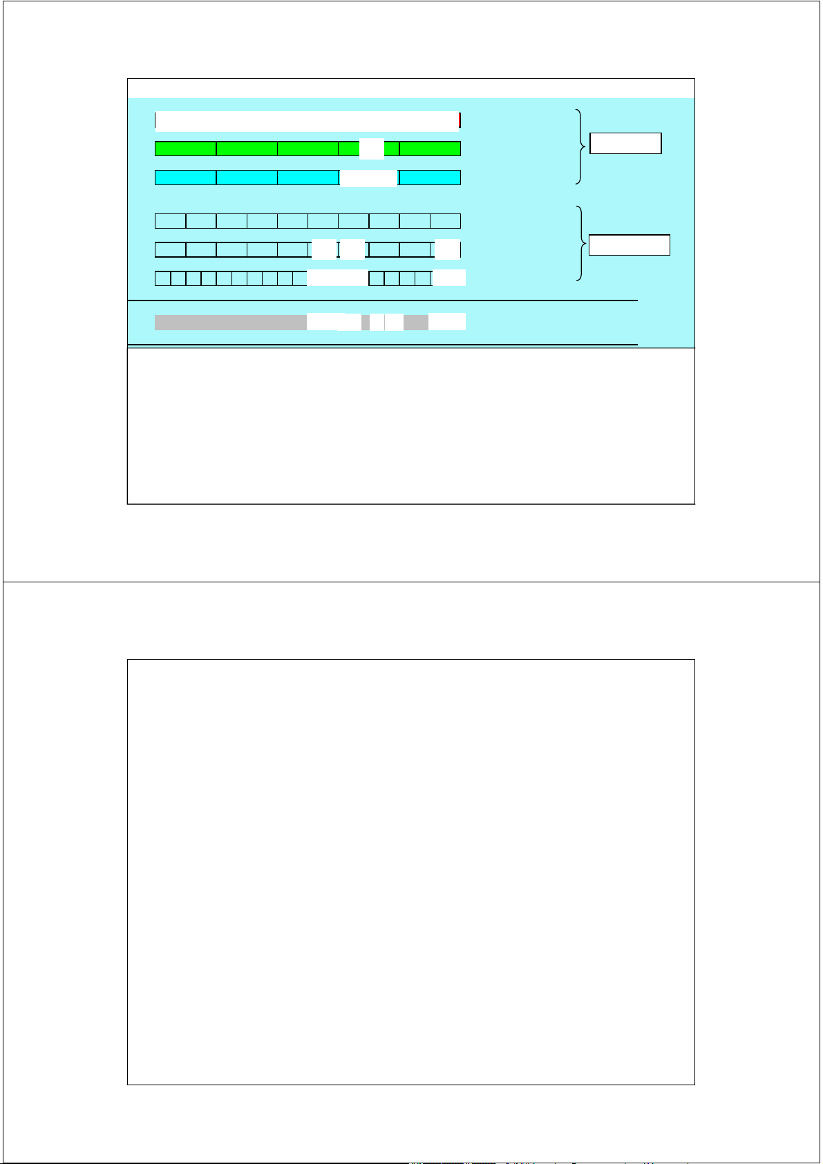
ξ 2. Nguyên lý trải phổ và sử dụng mã trong UMTS 2 2 Multiple Access Schemes FDMA TDMA CDMA Cod e 1 2 … Frequenc N y Tim e
Frequency Division Multiple Access (FDMA), different frequencies for different users
example Nordic Mobile Terminal (NMT) systems
Time Division Multiple Access (TDMA), same frequency but different timeslots for different users,
example Global System for Mobile Communication (GSM) GSM also uses FDMA
Code Division Multiple Access (CDMA), same frequency and time but users are
separated from each other with orthogonal codes 3 Shannon Equation C = B log2 (1 + SNR) B = Bandwidth C= Channel
SNR = Signal-to-noise ratio 4 CDMA
• Multiple users occupying the same band simultaneously by
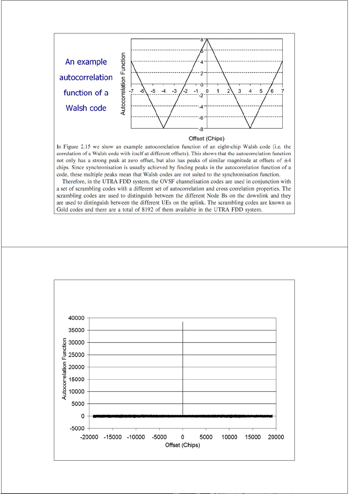
having different codes is known as Code Division Multiple Access or CDMA.
• This leads to universal frequency reuse.
• CDMA is a Spread Spectrum technique.
• Direct Sequence - CDMA is used in mobile communication. Data X Carrier Spread Data Modulation Code 5 Spread Spectrum
Means that the transmission bandwidth is much larger than the
information bandwidth i.e. transmitted signal is spread to a wider bandwidth
Bandwidth is not dependent on the information signal Benefits More secure communication
Reduces the impact of interference (and jamming) due to processing gain Classification
Direct Sequence (spreading with pseudo noise (PN) sequence)
Frequency hopping (rapidly changing frequency)
Time Hopping (large frequency, short transmission bursts)
Direct Sequence is currently commercially most viable 6 Spread Spectrum
Where does spread spectrum come from
First publications, late 40s
First applications: Military from the 50s Rake receiver patent 1956
Cellular applications proposed late 70s
Investigations for cellular use 80s IS-95 standard 1993 (2G)
1997/1998 3G technology choice
2001/2002 Commercial launch of WCDMA technology 7 Direct Sequence
In direct sequence (DS) user bits are coded with unique binary
sequence i.e. with spreading/channelization code
The bits of the channelization code are called chips
Chip rate (W) is typically much higher than bit rate (R)
Codes need to be in some respect orthogonal to each other.
Length of a channelization code
defines how many chips are used to spread a single
information bit and thus determines the end bit rate
Shorter code equals to higher bit rate but better Signal
to Interference and Noise Ratio (SINR) is required
Also the shorter the code, the fewer number of codes are available
Different bit rates have different geographical areas
covered based on the interference levels 8 Direct Sequence
Transmission (Tx) side with DS
Information signal is multiplied with
channelization code => spread signal
Receiving (Rx) side with DS
Spread signal is multiplied with channelization code
Multiplied signal (spread signal x code) is then
integrated (i.e. summed together)
If the integration results in adequately high (or low) values, the
signal is meant for the receiver 9 Direct Sequence 10 Direct Sequence 11 Processing gain and Spreading Despread narrowband signal Transmitted signal (Watts/Hz) before spreading Spread wideband signal Power density R Frequency W Interference for the part Received signal (Watts/Hz) we are interested in before despreading Power density Frequency 12 Processing gain and Spreading Transmitted signal Received signal (Watts/Hz) after despreading but before filtering Interference Power density Frequency Received signal (Watts/Hz) after despreading and after filtering Power density Frequency 13 Processing gain and Spreading
Spread spectrum systems reduce the effect of interference due to processing gain
Processing gain is generally defined as follows:
G[dB]=10*log10(W/R), where ’W’ is the chip rate and ’R’ is the user bit rate
The number of users takes negative effect on the processing gain. The loss is defined as:
Lp = 10*log10k, where ’k’ is the amount of users
Processing gain when the processing loss is taken into account is Gtot=10*log10(W/kR)
High bit rate means lower processing gain and higher power OR smaller coverage
The processing gain is different for different services over 3G mobile
network (voice, web browsing, videophone) due to different bit rates
Thus, the coverage area and capacity might be different for different
services depending on the radio network planning issues 14 Processing gain and Spreading
Processing gain is what gives CDMA systems the robustness against
self-interference that is necessary in order to reuse the available 5 MHz
carrier frequency over geographically close distances.
Examples: Speech service with a bit rate of 12.2 kbps
processing gain 10 log10(3.84e6/12.2e3) = 25 dB
For speech service the required SINR is typically in the
order of 5.0 dB, so the required wideband signal-to-
interference ratio (also called “carrier-to-interference
ratio, C/I ) is therefore “5.0 dB minus the processing” = -20.0 dB.
In other words, the signal power can be 20 dB under
the interference or thermal noise power, and the
WCDMA receiver can still detect the signal.
Notice: in GSM, a good quality speech connection requires C/I = 9–12 dB. 15 Principle of spreading 16 16 Principle of spreading 17 17
Trải phổ và giải trải phổ Spreading encoder 001 -11-11 -11-11 1-11-1 1-11-1 encoder 010 -1-111 11-1-1 -1-111 11-1-1 encoder 110 1-1-11 1-1-11 -111-1 -1 -1 -1 3 1 1 -3 1 -1 -1 3 -1 1-1-11 18
Trải phổ và giải trải phổ Spreading encoder 001 -11-11 -11-11 1-11-1 1-11-1 encoder 010 -1-111 11-1-1 -1-111 11-1-1 encoder 110 1-1-11 1-1-11 -111-1 -1 -1 -1 3 1 1 -3 1 -1 -1 3 -1 1-1-11 De-Spreading -1-1-13 11-31 -1-13-1 decoder -4 -4 4 001 1-11-1 -1-1-13 11-31 -1-13-1 decoder -4 4 -4 010 11-1-1 -1 -1 -1 3 1 1 -3 1 -1 -1 3 -1 -1-1-13 11-31 -1-13-1 decoder 1-1-11 4 4 -4 110 19
1 -1 -1 1 1 -1 -1 1 1 -1 -1 1 1 -1 -1 1 1 -1 -1 1 Code1
1 -1 -1 1 1 -1 -1 1 1 -1 -1 1 1 -1 -1 1 1 -1 -1 1 -1 1 -1 0 -1 1 Data1 Channel 1
-1 1 1 -1 1 -1 -1 1 -1 1 1 -1 0-1 0 0 1 1 -1 0 1 -1 -1 1 Data1*Code1
1 1 1 1 1 1 1 1 1 1 1 1 1 1 1 1 1 1 1 1 Code2 1 1 1 1 1 0 -1 0 -1 1 1 0 -1 Data2 Channel 2 1 1 1 1 1 1 1 1 1 1 0 0 -1 -1 0 -1 -10 1 1 1 1 0 0 -1 -1 Data2*Code2
0 2 2 0 2 0 0 2 0 2 1 -1 0 0 1 1 2 0 -1 1 Received data Rx - Received data ? Rx * Code1
0 -2 -2 0 2 0 0 2 0 -2 -1 -1 0 0 -1 1 2 0 1 1 Rx*Code1 Data de-spreaded -1 1 -1 0 1 Data despreaded Rx * Code2
0 2 2 0 2 0 0 2 0 2 1 -1 0 0 1 1 2 0 -1 1 RX*Code2 Data de-spreaded 1 1 1 1 1 0 0 1 1 0 Data despreaded 20
1 -1 -1 1 1 -1 -1 1 1 -1 -1 1 1 -1 -1 1 1 -1 -1 1 Code1
1 -1 -1 1 1 -1 -1 1 1 -1 -1 1 1 -1 -1 1 1 -1 -1 1 -1 1 -1 0 -1 1 Data1 Channel 1
-1 1 1 -1 1 -1 -1 1 -1 1 1 -1 0-1 0 0 1 1 -1 0 1 -1 -1 1 Data1*Code1
1 1 1 1 1 1 1 1 1 1 1 1 1 1 1 1 1 1 1 1 Code2 1 1 1 1 1 0 -1 0 -1 1 1 0 -1 Data2 Channel 2 1 1 1 1 1 1 1 1 1 1 0 0 -1 -1 0 -1 -10 1 1 1 1 0 0 -1 -1 Data2*Code2 0 2 2 0 2 0 0 2 0 2 1 0 -1 -2 0 -2 0 1 2 1 0 2 0 -1 -2 10 Received data Rx * Code1
0 -2 -2 0 2 0 0 2 0 -2 -1 -1 0 0 -1 1 2 0 1 1 Rx*Code1 Data de-spreaded -1 1 -1 0 1 Data despreaded Rx * Code2
0 2 2 0 2 0 0 2 0 2 1 -1 0 0 1 1 2 0 -1 1 RX*Code2 Data de-spreaded 1 1 1 1 1 0 0 1 1 0 Data despreaded 21 WCDMA System
WCDMA is the radio interface for UMTS systems
Wide bandwidth, 3.84 Mcps (Megachips per second)
Maps to 5 MHz due to pulse shaping and small guard bands between the carriers
Users share the same 5 MHz frequency band and time
UL and DL have separate 5 MHz frequency bands High bit rates
With Release ’99 theoretically 2 Mbps both UL and DL
384 kbps highest implemented Fast Power Control (PC)
=> Reduces the impact of channel fading and minimizes the interference 22 Codes in UMTS 23 Codes in WCDMA
Channelization Codes (=short code)
Codes from different branches of the code tree are orthogonal
Length is dependent on the spreading factor Used for
channel separation from the single source in downlink
separation of data and control channels from each other in the uplink
Same channelization codes in every cell / mobiles and therefore the additional scrambling code is needed Scrambling codes (=long code)
Very long (38400 chips = 10 ms =1 radio frame), many codes available Does not spread the signal
Uplink: to separate different mobiles
Downlink: to separate different cells
The correlation between two codes (two mobiles/NodeBs) is low Not fully orthogonal 24 Codes in UMTS Channelization codes separate different connection Scrambling codes separate cells/sectors Downlink 25 Codes in UMTS Channelization codes separate data/control channels Scrambling codes separate different mobiles Uplink 26 Codes in UMTS Channelization codes separate Channelization data/control codes separate channels different connection Scrambling codes separate cells/sectors Scrambling codes separate different mobiles Downlink Uplink 27 Codes in UMTS
Channelization Codes (=short codes)
Defines how many chips are used to spread a
single information bit and thus determines the end bit rate
Length is referred as spreading factor Used for:
Downlink: Separation of downlink connections to different users within one cell
Uplink: Separation of data and control channels from same terminal
Same channelization codes in every cell / mobiles
additional scrambling code is needed 28 Codes in UMTS
Scrambling codes (=long codes)
Very long (38400 chips), many codes available Does not spread the signal Used for
Downlink: to separate different cells/sectors
Uplink: to separate different mobiles
The correlation between two codes (two mobiles/NodeBs) is low 29 Codes used 30 30 Codes and their Use 31 31 Codes in WCDMA
The relation between downlink physical layer bit rates and codes
DPDCH : Dedicated Physical Data Channel 32
Orthogonal Variable Spreading Factor Codes OVSF code C4(1) Recursive rule 1111 C2(1) 11 C4(2) 11-1-1 C1(1) 1 C (0) 1 1 C4(3) 1-11-1 C (2i 1
) C ( )i,C ( ) C2(2) 2 i N N N C ( ) i 1-1 N
C (2 )i C ( )i, C ( ) C4(4) 2 i N N N 1-1-11 33
Channelisation code generation process 34
An example of the generation of two channelisation codes 35
An example of the generation of two channelisation codes 36 The orthogonality property of Walsh codes 37
The orthogonality property
of different length OVSF codes 38
The cross correlation of two
different Walsh codes with a non-zero offset 39
An example cross correlation function of two eight-chip Walsh codes 40
The cross correlation of codes from the same branch of the code tree 41 Channelisation code allocation rules 42 An example autocorrelation function of a Walsh code 43
The autocorrelation correlation properties of scrambling codes 44
The cross correlation properties of scrambling codes 45
Trường Đại học Bách Khoa Hà Nội
Khoa Điện tử Viễn thông Thông tin di động Mobile Communications
TS. Đỗ Trọng Tuấn
Bộ môn Kỹ thuật thông tin Hà Nội, 10-2010 1
Mạng thông tin di động 3G UMTS / W-CDMA
(Universal Mobile Telecommunications System)
ξ 3. Giao diện vô tuyến Uu 2 2
UMTS Network Architecture 3
Radio Interface - protocol architecture C-plane U-plane L3 L3: Radio Network RRC Layer LAC L2/LAC LAC LAC L2: Radio Link/Access Logical Control + Media Access channels Control RLC RLC RLC RLC L2/MAC MAC Transport channels L1 Physical Layer L1: Radio Physical Layer 4
UMTS Protocol Architecture 5 6
Logical, Transport and Physical channels
• Logical channel: an information stream dedicated to
the transfer of a specific type of information
• Transport channel: described by how data are transferred
• Physical channel: defined by the frequency, phase (I,Q) and code UE Node B RNC Logical Channels Transport Channels Physical Channels 7
Logical, Transport and Physical channels 8 Logical Channel - UMTS Node B UE 9
Transport Channel - UMTS UE Node B 10 Physical Channel - UMTS Node B UE 11 UMTS Channels 12 UMTS Logical Channels
Broadcast Control Channel (BCCH), Downlink (DL)
Paging Control Channel (PCCH), DL
Dedicated Control Channel (DCCH), UL/DL
Common Control Channel (CCCH), UL/DL
Dedicated Traffic Channel (DTCH), UL/DL
Common Traffic Channel (CTCH), Unidirectional (one to many) 13 UMTS Transport Channels
Dedicated Transport Channel (DCH), UL/DL, mapped to DCCH and DTCH
Broadcast Channel (BCH), DL, mapped to BCCH
Forward Access Channel (FACH), DL, mapped to BCCH, CCCH, CTCH, DCCH and DTCH
Paging Channel (PCH), DL, mapped to PCCH
Random Access Channel (RACH), UL, mapped to CCCH, DCCH and DTCH
Uplink Common Packet Channel (CPCH), UL, mapped to DCCH and DTCH
Downlink Shared Channel (DSCH), DL, mapped to DCCH and DTCH 14 UMTS Physical Channels
Primary Common Control Physical Channel (PCCPCH), mapped to BCH
Secondary Common Control Physical Channel (SCCPCH), mapped to FACH, PCH
Physical Random Access Channel (PRACH), mapped to RACH
Dedicated Physical Data Channel (DPDCH), mapped to DCH
Dedicated Physical Control Channel (DPCCH), mapped to DCH
Physical Downlink Shared Channel (PDSCH), mapped to DSCH
Physical Common Packet Channel (PCPCH), mapped to CPCH Synchronisation Channel (SCH) Common Pilot Channel (CPICH)
Acquisition Indicator Channel (AICH)
Paging Indication Channel (PICH)
CPCH Status Indication Channel (CSICH)
Collision Detection/Channel Assignment Indication Channel (CD/CA-ICH) 15 UMTS Channel Mapping 16
Layer 1 - up link physical channels Dedicated Physical Data Data Channel 0.667 ms Pilot FBI TPC TFI Dedicated Physical Control Channel Slot#1Slot#2 Slot#i Slot#15 frame Frame#1Frame#2 Frame#i Frame#72 superframe 10 ms FBI: FeedBack Indicator TPC: Transmit Power Control
TFI: Transport Format Indicator 17
Layer 1 - up link physical channels 18 Uplink Variable Rate 10 ms 1-rate 1/2-rate 1/4-rate 0-rate Variable rate R = 1 R = 1/2 R = 0 R = 0 R = 1/2 : DPCCH (Pilot+TPC+RI) : DPDCH (Data) 19
Layer 1 - down link physical channels DPCCH DPDCH Pilot TPC TFI Data 0.667 ms Slot#1Slot#2 Slot#i Slot#15 frame Frame#1Frame#2 Frame#i Frame#72 superframe 10 ms 20
Layer 1 - down link physical channels 21
Downlink Variable Rate (DTX based) 0.625 ms 1-rate 1/2-rate 1/4-rate 0-rate
: DPCCH-part (Pilot+TPC+RI) : DPDCH-part (Data) 22 23 Node B 24
Multiplexing transport channels onto physical channels trasport channels multiplexing DCH DCH coding rate interleaving matching interleaving rate matching interleaving DCH multiplexing dynamic intra frame DCH (up link) interleaving coding rate interleaving matching interleaving static inter frame interleaving 25
Mapping transport channels onto physical channels 26 Node B 27 Node B 28 Node B 29 30 31 32 33 34 35 36 37 38 39
Mapping between Logical, Transport and Physical channels 40 41 Transport Channels
In WCDMA there exists two types of transport channels: Dedicated Channels (DCHs)
Resources are reserved for a single user only (continuous and independent from the DCHs of other UEs) Common channels
Resources are shared between users
The main transport channels used for packet data transmissions in WCDMA are called DCH
Forward Access Channel (FACH) 42 Transport Channels DCH is used to carry User data
All higher layer control information, such as handover commands
DCH is characterized by features such as Fast power control Soft handover
Fast data rate change on a frame-by-frame basis is supported in the uplink
In the downlink data rate variation is taken care of
either with a rate-matching operation or with
Discontinuous Transmission (DTX) instead of varying
spreading factor frame-by-frame basis 43 Transport Channels
If downlink rate matching is used then data bits are either
Repeated to increase the rate
Punctured to decrease the rate
With DTX the transmission is off during part of the slot
FACH is a downlink transport channel used to carry Packet data
Mandatory control information, e.g. to indicate
that random access message has been received by BTS
Due to the reason that FACH carries vital control information FACH has
to have such a low bit rate that it can be received by all UEs in the cell 44 Transport Channels
However, there can be more than one FACH in a cell which makes it
possible to have higher bit rates for the other FACHs
The FACH does not support fast power control
In addition to FACH there are five different common channels in WCDMA: Broadcast Channel (BCH)
Used to transmit information specific to the UTRA network or for a given cell, e.g. random access codes
Channel needs to be reached by all UEs within the cell Paging Channel (PCH)
Carries data relevant to the paging procedure, i.e. when the network wants to
initiate communication with the terminal
Terminals must be able to receive the paging information in the whole cell area 45 Transport Channels
Random Access Channel (RACH)
Uplink transport channel intended to be used to carry control information from
the terminal, such as requests to set up a connection
Uplink Common Packet Channel (CPCH)
Extension to the RACH channel that is intended to carry packet-based user data in the uplink direction
Dedicated Shared Channel (DSCH)
Carries user data and/or control information; it can be shared by several users 46 Transport Channels
From the common channels DSCH was optional feature that was
seldom implemented by the operators and later replaced in practice
with High Speed Downlink Packet Access (HSDPA)
3GPP decided to take DSCH away from Release 5 specifications onwards
Also CPCH has been taken out of the
specifications from Rel’5 onwards as it was not
implemented in any of the practical networks 47 48 49 50 51
Frame structure for uplink DPDCH/DPCCH 52 53 54 55 56 57
Trường Đại học Bách Khoa Hà Nội
Khoa Điện tử Viễn thông Thông tin di động Mobile Communications
TS. Đỗ Trọng Tuấn
Bộ môn Kỹ thuật thông tin Hà Nội, 10-2010 1
Mạng thông tin di động 3G UMTS / W-CDMA
(Universal Mobile Telecommunications System)
ξ 4. Một số cơ chế cơ bản tại UTRAN-FDD 2 2 Cell Interference Need to control: • Power • Range (coverage)
• Processing Gain/Spreading Factor per user • Overall loading 3 3 Cell Breathing ) 1,6 (km 1,4 er 1,2 1 diamet 0,8 Cell 0,6 0,4 0,2 0 10 20 30 40 50 Users 4 Cell Breathing
A UE on the cell edge is transmitting with max power
Another UE becomes active
Increased interference
the received signal from the UE on the cell edge is too weak!
Effective cell size decreases with increasing number of users
There is a trade-off between capacity and coverage
Cell size depends on both maximum Tx power and
number of active users (in the same and other
cells) which results in cell breathing 5
Cell breathing phenomena
Cas 1 : 10 utilisateurs
Cas 2 : 20 utilisateurs Case 1: 20 users Case 2: 10 users
-10 < C/I < -5 dB
-15 < C/I < -10 dB
-15 < C/I < -50 dB cellu le cells s 6 Cell Breathing 7 Cell Breathing
• Effective range of cell is reduced on higher loading due to interference caused by additional channels
• Adjacent cells also breathed
• Soft handover region reduces 8
CELL BREATHING AND SOFT CAPACITY
Cel breathing is used to describe the way in which the
coverage of a Node B changes (or breathes) in response to
changes in the network load. To show this effect let us start
with a very simple example of a UE with a fixed transmit
power communicating with a single nearby Node B. 9 9 Cell Breathing 10 Voice Activity Detection
Reducing multiple access interference Human speech: 42% results in a capacity gain
FDMA and TDMA cellular systems
Frequencies are permanently assigned
Capacity in FDMA and TDMA systems is fixed and primarily bandwidth limited. 11
The relationship between the received power and the number of users 12
Received power and the number of users
Figure 2.20 shows a plot of the required received power, C, against the
number of users N based on Equation (2.2) and assuming a processing
gain of 256, a value for Eb/I0 +N0 of 7 dB, a value for of 50%, a value for
i of 55% and a receiver noise figure of 5 dB. This shows the manner in
which the required received power increases as the number of users
increases. The increase in received power is gradual at first, but then it
starts to increase more rapidly as more users are added to the network.
At some point we reach a value for N that causes the denominator in
Equation (2.2) to become zero and, hence, C goes to infinity. Since no
practical transmitter can generate an infinite amount of power, this value
of N can never be reached in a practical system and it is termed the ‘pole
capacity’ of the network. If a practical network starts to approach its pole
capacity then it can become unstable, with the transmit power
requirements of the UEs varying dramatically for very small changes in the
network load. Therefore, practical networks are usually designed to
operate at a certain fraction of their pole capacity and new calls are
rejected once this limit is reached. 13 13 Noise Rise
The system load in the uplink direction can be measured in terms of equivalent
‘noise rise’ at the Node B, which is defined as the additional power that must
be delivered by a UE at the Node B to overcome the interference generated by
other UEs. Returning to Figure 2.20, we can see that with a single user on the
network, this UE must be received with a power of −1205 dBm. However, if the
network load increases to 10 users, then each UE must deliver a power of
−1199 dBm at the Node B receiver, i.e. an increase or noise rise of 0.6 dB. In a
practical network, an operator may choose to limit the network load to 75% of
the pole capacity and this equates to a noise rise of 6 dB. Once the Node B
detects that the total received noise and interference power at its receiver is 6
dB greater than the thermal noise alone, it will reject any new calls. 14 14
Cell radius and noise rise Charge de la cellule = 20 % Cell load = 20% of the de la capacité maxi maximum mum capacity R Niveau d’interf Interference érence level= = y y d dB B R et R R’ so and nt R’ les rayons d are the cell es cellu les dans les deux radius in the 2 load Noise Rise = 2 dB situations de charg situations e Charge de la cellule = 50 % Cell load = 50% of the de la capacité maxi maximum mum capacity R R’ R Niveau d’inter Interference férence level= = y + y + 2 2 d dB B 15 CELL BREATHING 16
Coverage and capacity planning
• In CDMA coverage and capacity are tight together:
• When the number of users increases, the interference levels increases and
therefore the needed powers in order to keep constant quality. Due to infinite
power resources this means that the coverage decreases.
• This leads to Cell Breathing: the coverage area changes as the load of the cell changes
• Therefore, the coverage and the capacity has to plan simultaneously 17 Cell Interference 18 18 “Near-far problem” The uplink issue D1 D2 D1> D2
• UEs closer to Node B may create too much interference.
• Requirements: fast power control in UE
• Target: all UEs are received at the Node B with the same power 19 Transmit Power Control Near – far problem despreading MS MS Node B Power control despreading MS MS Node B TPC Minimize Increase is essential the Tx power the system capacity 20 Power Control
Aims to reduce interference Near-far problem c2 Pt2
Reduces power consumption in Pr2 Base Station the MS Pt1 Pr1 Methodologies c1 Open-loop Sum of transmit power and the received power is kept constant Closed-loop d2 Signifies the other party to increase or decrease d1 transmit power by a Distance Pt1: Power transmitted from c1 pre-defined power step Pt2: Power transmitted from c2
Pr1: Power received at base station from c1
Pr2: Power received at base station from c2 Pr1 = Pr2 21/53 21 Power Control 22 Power Control 23 Power Control Closed-Loop Power Control
Feedback loop with 1.5kHz cycle to
adjust uplink / downlink power to its minimum
Even faster than the speed of
Rayleigh fading for moderate mobile speeds Outer Loop Power Control
Adjust the target SIR (Signal to
Interference Ratio) setpoint in base
station according to the target BER, commanded by RNC 24 Power Control
Inner Loop Power Control in the Downlink : This procedure enables a
base station to adjust its transmit power in response to TPC commands from
the UE. Power is adjusted using a step size of 0.5 or 1 dB. The objective
here is to maintain a satisfactory signal-to-interference ratio at a UE using as
little base station transmitter signal power as possible.
Inner Loop Power Control in the Uplink This procedure is used by the UE
to adjust its transmit power in response to a TPC command from a base
station.With each TPC command, the UE transmit power is adjusted in steps
of 1, 2, or 3 dB in the slot immediately following the decoding of TPC commands.
A TPC command may be either 0 or 1. If it is 0, it means that the transmitter
power has to be decreased. If it is 1, the transmitter power is to be increased. 25 Power Control 26 Power Control 27 Transmit Power Control
Power Control: Manages radio link quality - Uplink is handled per
mobile (UE), downlink per physical channel
Ensures that transmission powers are kept at a minimum level and
that there is adequate signal quality and level at the receiving end
Closed loop transmit power control in the Uplink SIR Target SIR Tslot Up Link Transmit power control SIR measurement 1dB step Down Link TPC bit 28
TPC and “Near-far” problem 29
Fast closed loop PC (TPC) 30
Fast closed loop PC (TPC) 31 Handoff (1/2) Handoff :
• Cellular system tracks mobile stations in order to maintain their communication links.
• When mobile station goes to neighbor cell, communication link switches from current cell to the neighbor cell. Hard Handoff :
• In FDMA or TDMA cellular system, new communication establishes after breaking current
communication at the moment doing handoff. Communication between MS and BS
breaks at the moment switching frequency or time slot. switching Cell B Cell A
Hard handoff : connect (new cell B) after break (old cell A) 32 Soft Handoff (2/2) Soft Handoff :
• In CDMA cellular system, communication does not break even at the moment doing
handoff, because switching frequency or time slot is not required.
transmitting same signal from both BS A and BS B simultaneously to the MS Σ Cell B Cell A
Soft handoff : break (old cell A) after connect (new cell B) 33
Mobility/Handoff in Umbrella Cells Avoids multiple handoffs. 34 Hand Over 35 Soft Hand Over 36 Soft Hand Over
• UE combines symbols received from each Node B.
• RNC selects the best radio frame from each Node B Node B #1 Node B #2
As the mobile moves away from Node B #1, the link between the mobile and
Node B #1 becomes weaker. Before the link becomes marginal or breaks,
another link is established between the mobile and the second Node B. This
is known as a soft handover. If one link experiences a deep fade (e.g., due to
shadowing of the radio signal or interference in congested areas), the call will
stay up as long as the other link is maintained. This makes soft handovers
more reliable than hard handovers, where only a single link is maintained at any given time. 37 Softer Hand Over
• UE combines symbols received from each cell.
• Node B combines symbols received from each cell. 38 Inter-RAT Hard Handover 39
Cell Reselection versus Handover 40 Handover 41 Handover Process
A basic HO process consists of three main phases measurement phase Intra-frequency Measuremetnt criteria Measurement reports Inter-frequency MEASUREMENT Traffic volume Quality Internal Algorith parameters decision phase Handover criteria DECISION Change of best cell. Changes in the SIR level. Changes in the ISCP level. Handover signalling Periodical reporting. Radio Resource Allocation EXECUTION Time-to-trigger. execution phase.
Network Evaluated Handover (NEHO)
Mobile Evaluated Handover (MEHO) 42 Handover in UMTS
Handover essential to guarantee user mobility in a mobile communications network. Handover Algorithm
Assumption: a UE, currently connected to signal A,
is located in cell A and moving towards cell B.
Pilot signal A, deteriorates, approaching lower Summed Signal
Handover threshold Handover Triggering Margin
Signal A equals lower threshold.
Based on UE measurements, RNC recognises an Upper
available neighbouring signal (signal B), with threshold
adequate strength to improve quality of connection.
RNC adds signal B to Active Set. Lower
UE has two simultaneous connections to UTRAN and threshold
benefits from summed signal (signal A + B) Signal Strength
When quality of signal B becomes better than signal A
RNC keeps this as starting point for HO margin calculation. Signal B Signal A
Signal B greater than defined lower threshold.
strength adequate to satisfy required QoS. (1)(2)(3) time
strength of summed signal exceeds defined upper
threshold, causing additional interference. RNC Cell A Cell B
deletes signal A from Active Set. 43 Hand over
-Active set : bao gồm tất cả các cells liên quan đồng thời đến quá trình kết
nối chuyển giao mềm. UE giải điều chế tín hiệu nhận được từ các cell này
và kết hợp thành tín hiệu cuối cùng tương ứng với việc phân tập với hệ số
khuếch đại khoảng 2 dB. Danh sách cell tích cực (active set) bao gồm hai
hay nhiều cells trong một hệ thống FDD.
- Monitored set : bao gồm các cell không nằm trong active set nhưng được
theo dõi bởi UE do thuộc danh sách các cell lân cận.
- Detected set : bao gồm các cell được phát hiện bởi UE nhưng không thuộc hai tập trên. 44
Chuyển giao mềm - SHO
- Giả thiết UE đang thu tín hiệu mạnh nhất từ cell 1, khi đó danh sách tích
cực chỉ có duy nhất cell 1.
- Nếu tại thời điểm t1 xác định, kênh pilot (hoa tiêu) của cell 2 có tín hiệu đủ
lớn, nghĩa là khoảng chênh lệch công suất giữa cell 1 và cell2 nhỏ hơn một
giá trị ngưỡng Δ1. Khi đó pilot 2 có thể được sử dụng và vì vậy cell 2 sẽ
được bổ sung vào danh sách tích cực. Từ thời điểm đó, UE sẽ đồng thời
liên lạc với cell 1 và cell 2 , tương đương với việc phân tập do kết hợp tín
hiệu thu từ hai cell nói trên. Δ1 = L - H1, trong đó L = reporting range, và H1
= độ chênh lệch công suất bổ sung - addition hysteresis.
- Nếu tại thời điểm t2, pilot 1 có mức tín hiệu giảm và khoảng chênh lệch
giữa pilot 2 và pilot 1 lớn hơn một giá trị ngưỡng Δ2, khi đó pilot 1 sẽ không
tiếp tục được sử dụng và bị loại bỏ khỏi Active Set. Do vậy, từ thời điểm t2,
UE chỉ kết nối với cell2 Ngưỡng Δ2 = L + H2, trong đó H2 = độ chênh lệch
công suất loại bỏ - removal hysteresis. 45
Initial acquisition at power on 46
Mobile Originated Voice Call Flow 47
Mobile Originated Voice Call Flow RB - Radio Bearer
The service provided by the Layer 2 for the transfer of user data between UE (User
Equipment) and UTRAN (UMTS Terrestrial Radio Access Network). 48 49
Trường Đại học Bách Khoa Hà Nội
Khoa Điện tử Viễn thông Thông tin di động Mobile Communications
TS. Đỗ Trọng Tuấn
Bộ môn Kỹ thuật thông tin Hà Nội, 10-2010 1 WCDMA network planning 2 2 CELL PLANNING PROCESS 3 Optimization Life Cycle 4
Pre-Deployment Optimization
- Traffic assumption/capacity objectives - Building and vehicle Project Setup – penetration loss Coverage Objectives Equipment Selection - Service area - Coverage probability Nominal Design –
Assumption of Site Configuration Build-Out Methodology Demand Distribution Map 5 Initial Optimization 6 In-Service Optimization 7 Continuous Optimization 8 Naming Conventions 9 Network Planning
Cells, LAs, and RAs are used only in Idle Mode.
In Connected Mode the UTRAN Registration Area (URA) 10
Network Planning - Network Areas 11
Reference Network - UTRAN (R99) 12 Main Interfaces to
Consider for Network Planning 13
WCDMA Coverage Definition –
What Defines WCDMA System Coverage? 14
WCDMA Coverage Definition –
What Defines WCDMA System Coverage?
- System Acquisition Based Coverage: Defined in terms
of Pilot Ec/Io (chip energy over power spectral density).
- Traffic Based Coverage: Defined in terms of DCH Eb/Nt at a target BLER. 15
WCDMA Coverage Definition –
What Defines WCDMA System Coverage? 16
WCDMA Coverage Definition –
What Defines WCDMA System Coverage? 17
WCDMA Coverage Definition –
What Defines WCDMA System Coverage? 18
WCDMA Coverage Definition –
What Defines WCDMA System Coverage? 19
WCDMA Coverage Definition –
What Defines WCDMA System Coverage? 20
WCDMA Coverage Definition –
What Defines WCDMA System Coverage? 21
Walfisch-Ikegami Model – Standard Model 22
Walfisch-Ikegami Model – Free-Space Loss 23 Walfisch-Ikegami Model
Rooftop-Street Diffraction Loss 24 Walfisch-Ikegami Model
Multi-Screen Diffraction Loss 25 COST 231 Walfish-Ikegami model Frequency f: 800 - 2000 MHz
Base Station Antenna Height hb : 4 - 50 m MS Antenna Height hm : 1 - 3 m Distance d: 0.02 - 5 km BS 26 27 28 29 30 31 32 33 UMTS Network - 3GPP R99 34 UMTS Network - 3GPP R4 35
Chuyển mạch mềm MSS – Mobile Soft Switch 36 UMTS Network - 3GPP R5 37 38 39 50000000 45000000 40000000 35000000 30000000 25000000 Thue bao 3G 20000000 Tong thue bao 15000000 10000000 5000000 0 Thang 4/2010 8/2010 12/2009 40
Trường Đại học Bách Khoa Hà Nội
Khoa Điện tử Viễn thông Thông tin di động Mobile Communications
TS. Đỗ Trọng Tuấn
Bộ môn Kỹ thuật thông tin Hà Nội, 10-2010 1
Mạng không dây Wi-Fi , WiMAX ( Wireless Networks) 2 2 Overview What is Wireless? The term wireless refers to telecommunication technology,
in which radio waves, infrared waves and microwaves, instead
of cables or wires, are used to carry a signal to connect communication devices.
These devices include pagers, cell phones, portable PCs, computer networks, location
devices, satellite systems and handheld digital assistants. 3 3 Wireless Landscape Wireless Transmission Speed Technology Distance Bluetooth PAN :: 1- 10 m 1 Mbps WLAN 802.11b WLAN :: n*10 – 100 m 11 Mbps WLAN 802.11a, g WLAN :: n*10 – 100 m 54/128 Mbps WiMax 802.16 WMAN :: n – n*10 miles 75 Mbps 2G digital cellular WWAN - Nationwide 14 Kbps 2.5G digital cellular WWAN - Nationwide 384 Kbps 3G digital cellular WWAN - Nationwide 2-10 Mbps
WiMAX as a last-mile alternative for remote areas not currently served by DSL or cable 4 4 Wireless Technologies WAN WA (Wide (W Area ide Netw Area or o k) MAN (Metropolitan A (Metropolitan rea Netw rea ork) LAN (Local A (Local rea Network) PAN PA (Personal Area (Personal Network) ork PAN PA LAN LAN MAN MAN WAN WAN 802.11a, 1 802.1 1b, 1 1a, 1 1 1b, 1 g 1 802.11 802.1 GSM, GPRS, Standards Bluetooth HiperLAN2 MMDS, LMDS CDMA, 2.5–3G 2 Speed < 1 Mbps 2 - 54 Mbps 75 Mbps 9,6 Kbps – 2Mbps Range Short Medium Medium–Long Medium–Lon Long Peer-to-Peer Family, Family Office, Office, Last PDAs, Mobile
Applications Device-to-Device and Enterprise and Mile A Mile ccess A Phones, C Phones, ellular C Access 5 5
Mạng không dây Wi-Fi IEEE 802.11 6 6
Wi-Fi™ and IEEE 802.11 Standards 802.11a: 5GHz, 54Mbps 802.11b: 2.4GHz, 11Mbps 802.11d: Multiple regulatory domains 802.11e: Quality of Service (QoS) 802.11f:
Inter-Access Point Protocol (IAPP) 802.11g: 2.4GHz, 54Mbps 802.11h:
Dynamic Frequency Selection (DFS) and Transmit Power Control (TPC) 802.11i: Security 802.11j:
Japan 5GHz Channels (4.9-5.1 GHz) 802.11k: Measurement
IEEE 802.11n : adding multiple-input multiple-output (MIMO) 7 7
Wi-Fi™ and IEEE 802.11 Standards 8 8
Unlicenced Frequency Bands
ISM : Industrial, Scientific and Medical U-NII : Unlicenced National Information Infrastructure
Defined cable-free local area network with either fixed or mobile locations that
transmit at either 1 or 2 Mbps which was insufficient for most network applications
A new standard was developed for sending packetsized data traffic over radio waves
in the unlicensed 2.4 Ghz band.
Unlicensed, means it does not have to be certified by the FCC, and devices could
possible share the bandwidth with other devices such as cordless phones, oven etc. 9 9 Frequency Bands 10 10 Standard Selection 11 11 Standard Selection 802.11b 802.11a 802.11g Frequency 2.4 GHz 5 GHz 2.4 GHz Band Availability Worldwide US/AP Worldwide Maximum 11 Mbps 54 Mbps 54 Mbps Data rate Cordless Phones Cordless Phones Other Microwave Ovens HyperLAN Microwave Ovens Services Wireless Video Devices Wireless Video (Interference) Bluetooth Devices Bluetooth Devices The Laws of Radio Dynamics: Higher Data Rates = Shorter Transmission Range Higher Power Output
= Increased Range, but Lower Battery Life
Higher Frequency Radios = Higher Data Rates Shorter Ranges 12 12 Ad Hoc Topology
Cấu hình tùy biến (không phụ thuộc) IBSS
Peer-to-Peer (Ad Hoc) Topology
Can consist of 2 or more PCs with wireless network adapters. Sometimes called an Independent BSS (IBSS). Limited range. No AP is needed ! 13 13 Ad Hoc Topology 14 14 Infrastructure Topology
Cấu hình phụ thuộc - BSS AP is needed ! 15 15 Infrastructure Topology 16 16
Radio Signal Interference
Since the frequency is unlicensed, any
device operating in the 2.4 GHz spectrum may cause network
interference with a 802.11b wireless
device. Some devices that may prove
troublesome include 2.4 GHz cordless
phones, microwave ovens, adjacent
public hotspots, and neighboring 802.11b wireless LANs. 17 17 WLAN Devices AP : Điểm truy nhập Access Points
In-building Infrastructure Bridge, Repeater 18 18 WLAN Devices Clients Antenna
• 2.4 GHz client adapter (802.11b,g) • 2.4GHz
• 5 GHz client adapter (802.11a) • 5 GHz Antennas • PCI card for Desktop • PCMCIA card for Laptop
(Personal Computer Memory Card
International Association )
• USB card for Desktop & Laptop 19 19 WLAN Devices
Optional 2.4GHz Antennas for Long Range • 13.5 dBi Yagi • 21 dBi Solid Dish Distances over For distances up to 7.3 miles @ 2 Mbps 25+ miles @ 2 Mbps 11.7 Km @ 2 Mbps 40+ Km @ 2 Mbps 3.6 miles @ 11 Mbps 20.5 miles @ 11 Mbps 5.8 Km @ 11 Mbps 33 Km @ 11 Mbps
Note: Distances include 50 feet of low loss cable and 10 dB fade margin 20 IEEE 802.11 channels 5 MHz 21 21
IEEE 802.11 Protocols Architecture octet CRC-32 Media Access Control
DCF: Distributied Coordination Functions -> Contention Access
PCF: Point Coordination Functions
-> Contention - Free Access ( polling ) 22 22 Hidden terminal problem Hidden Node C A B C B A’s signal C’s signal A strength strength space Hidden terminal problem Signal fading: B, A hear each other B, A hear each other B, C hear each other B, C hear each other A, C can not hear each other A, C can not hear each other means A, C unaware of their interfering at B interference at B 23 23 MAC::CSMA/CA
CarrierSense Multiple Access / Collision Avoidance B¾t ®Çu N NAV=0 ? Y Kiểm tra đường truyền Đường N Quay lui truyền rỗi ngÉu nhiª n Y
Tham số cấp phát tài nguyên mạng Truyền khung
NAV: Network Alocation Vector Y N Truyền ACK ? thµnh c«ng 24 24
IEEE 802.11 MAC Protocol: CSMA/CA 802.11 sender
1 if sense channel idle for DIFS then transmit entire frame (no CD) sender receiver 2 if sense channel busy then DIFS start random backoff time
timer counts down while channel idle data transmit when timer expires
3 if no ACK, increase random backoff interval, repeat 2 SIFS 802.11 receiver ACK - if frame received OK
return ACK after SIFS (ACK needed due to hidden terminal problem)
DIFS : DCF Inter-Frame Space
SIFS : Short Inter-Frame Space 25 25
IEEE 802.11 MAC Protocol: CSMA/CA DIFSRTS data sender SIFS SIFS CTS SIFS ACK receiver NAV (RTS) DIFS data other NAV (CTS) stations t defer access contention •
Station can send RTS with reservation parameter after waiting for DIFS (reservation
determines amount of time the data packet needs the medium and the ACK related to it).
Every node receiving this RTS now has to set its NAV (Network Allocation Vector - it
specifies the earliest point at which the node can try to access the medium again. •
Acknowledgement via CTS after SIFS by receiver (if ready to receive) •
Sender can now send data and receive acknowledgement via ACK if data is received without error. 26 26
Channel Access in 802.11 3 4
Node 1 has to communicate with Node 2 RTS2 RTS2 CTS1
3 and 4 have to remain silent till 1 1 2 finishes transmission to 2 SIFS SIFS SIFS DIFS MEDIUM BUSY RTS2 DATA CTS1 ACK NAV(RTS) NAV(CTS) 27 27
IEEE 802.11 frame: addressing 2 2 6 6 6 2 6 0 - 2312 4 frame address address address seq address duration payload CRC control 1 2 3 control 4 Address 3: used only Address 1: MAC address in ad hoc mode of wireless host or AP Address 3: MAC address to receive this frame of router interface to which AP is attached Address 2: MAC address of wireless host or AP transmitting this frame 28 28
IEEE 802.11 frame: addressing Internet router H1 R1 AP R1 MAC addr AP MAC addr dest. address source address 802.3 frame
AP MAC addr H1 MAC addr R1 MAC addr address 1 address 2 address 3 802.11 frame 29 29 IEEE 802.11 frame: more duration of reserved frame seq # transmission time (RTS/CTS) (for reliable ARQ) 2 2 6 6 6 2 6 0 - 2312 4 frame address address address seq address duration payload CRC control 1 2 3 control 4 2 2 4 1 1 1 1 1 1 1 1 Protocol To From More Power More Type Subtype Retry WEP Rsvd version AP AP frag mgt data frame type (RTS, CTS, ACK, data) 30 30
System Architecture of an infrastructure network Station (STA) 802.11 LAN 802.x LAN
terminal with access mechanisms to the wireless medium and radio contact to the access point STA1 Basic Service Set (BSS) BSS1 Portal
group of stations using the same Access radio frequency Point Access Point Distribution System
station integrated into the wireless Access ESS
LAN and the distribution system Point Portal BSS2
bridge to other (wired) networks Distribution System
interconnection network to form one
logical network (EES: Extended STA2 802.11 LAN STA3
Service Set) based on several BSS 31 31
WLAN network architecture 32 32 Mạng không dây WiMAX IEEE 802.16
Worldwide Interoperability for Microwave Access 33 33 34 34 WiMAX: History
2001:802.16 (interest : 10-66GHz, line of sight, point to point applications)
2003: 802.16a standard (interest: 2-11GHz, NLOS point to
multi-point applications, upto 75MHz)
2004: 802.16d ( upgrade of 802.16a, modifications and interoperability )
2005: 802.16e ( offers mobility at vehicular speed) 35 35
Some Technical Specs on WiMax 36 36 37 37
WIMAX TOWER WIMAX RECEIVER 38 38 WiMax 39 39
WiMAX network architecture 40 40 802.16 Protocol Architecture
IEEE 802.16 Protocol Architecture has 4 layers: Convergence, MAC,
Transmission and physical, which can be mapped to two OSI
lowest layers: physical and data link. 41 41
802.16 Protocols Architecture 42 42
4 types of Scheduling Service
Unsolicited Grant Service (UGS)
Real-time, periodic fixed size packets (e.g. T1 or VoIP)
Restrictions on bw requests
Real-Time Polling Service (rtPS)
Real-time, periodic variable sizes packets (e.g MPEG)
BS issues periodic unicast polls.
Non-Real-Time Polling Service (nrtPS)
Variable sized packets with loose delay requirements (e.g. FTP)
BS issues unicast polls regularly. Best Effort Service Never polled individually 43 43 Connections
802.16/WiMAX is connection oriented
For each direction, a connection identified with a 16 bit CID
Each CID is associated with a Service Flow ID (SFID) that determines
the QoS parameters for that CID 44 44 QoS Mechanism 45 45 WiMAX & Wi-Fi WiMAX WiMAX WiMAX Wi-Fi Wi-Fi Wi-Fi Urban Rural Suburbs Urban 46 46 Intel WiMAX Vision Wi-Fi Nomadic Broadband Broadband Access complementary to for Enterprise 3G, EDGE & WiFi 802.16-2004 802.16-e Broadband Access for Public hotspots 802.16-2004 Broadband Access @ Home Wi-Fi complementary to DSL & Cable 802.16-2004 WiFi
*Other brands and names are the property of their respective owners. 47 47 FUTURE OF WiMAX
WiMax will be deployed in three stages:
In the first phase WiMaX technology (based on IEEE 802.16-
2004) provides fixed wireless connections
In the second phase WiMaX will be available as a cheap and
self-installing Subscriber Terminal (ST), linked to PC and to antenna
The third phase enables portability, thus WiMAX (based on
IEEE 802.16e) will be integrated into commercial laptops 48 48
Mobile Broadband Technology map IP Based Convergence IP Core Wi-Max Wi-Max 802.16d 802.16e Backhaul Wi-Fi 802.11 In-Building Rural Sub-Urban Urban Hotspots PICO MACRO MICRO Access Cellular Mobility
GSM (EDGE) & UMTS (HSDPA) IS-95, CDMA2000 49 49
Key technologies are evolving to meet the Wireless Broadband Requirements 4G Air Interfaces 1x HRPDA CDMA EVDO 3GPP2 Mobile 2000-1X 1x EVDV 1x EVDV Wide Area MOBILE Rel. C Rel. D BROADBAND GSM GPRS EDGE UMTS HSPA LTE 3GPP 802.16e (Mobile WIMAX) Mobile Industry Nomadic Metro Area 802.16a/d (Fixed NLOS) Coverage/Mobility 802.11n Fixed Wireless Industry (smart antennas) 802.11 ea Mesh extns. 802.16 (Fixed LOS) DSL Experience Dial Up Fixed Local Ar 802.11b/a/g Data Rates (kbps) 100,000 +
Higher Data Rate / Lower Cost per Bit 50 WMAX/LTE Specifications Radio Access Network Packet Core + OFDMA Technology + New all IP collapsed + Downlink 100Mbps+ architecture + Uplink 20-50Mbps+ + User <10msec latency + Centralized mobility and application layer + Flexible spectrum – (IMS based) 1.25-20MHz + FDD and TDD + E2E QOS + VoIP ~3x time + Access technology UMTS capacity agnostic + MIMO/Beamforming + Connect to legacy + E2E QOS GSM/UMTS core (LTE)
Motorola Confidential Proprietary, LTE CxO Overview, Rev 1
MOTOROLA and the Stylized M Logo are registered in the US Patent & Trademark Office. All other product or service names are the property of their respective owners. © Motorola, Inc. 2007 51
HSDPA vs. WiMAX Air Interface Performance Attribute HSDPA 802.16e 10 MHz Spectrum Occupancy (5 DL+ 5 UL) 10 MHz 5 MHz TDD, 70% DL (data) TDD, 70% DL (data) Duplexing FDD TDD, 50% DL (voice) TDD, 50% DL (voice) 1 site, 1 sector reuse 1 site, 1 sector reuse 1 site, 1 sector reuse Frequency Reuse 3 sectors per site 3 sectors per site 3 sectors per site "Macro" BTS/Node B "BS2.2" w/o TxAA "BS2.2" w/o TxAA BS Configuration 20W output 2W output 2W output 2.8km Intersite distance 1.2km Intersite distance 1.2km Intersite distance System Configuration 30 km per hour 30 km per hour 30 km per hour Sector Throughput (F/L) 1400 3200 1376
Web Browsing with TCP/IP (kbps) Sector Throughput (F/L) 3000 6000 2580 Ful buffer Traffic (kbps) Sector Throughput (R/L) 1100 1500 645 Ful buffer Traffic (kbps) Voice Capacity (F/L) (Erlangs) 120 150 75 (est.) Voice Capacity (R/L) (Erlangs) 80 120 60 (est.)
F/L Data Spectral Efficiency web browsing 0.28 0.46 0.40 (bps/Hz)
F/L Data Spectral Efficiency 0.60 0.86 0.74 full buffer (bps/Hz)
R/L Data Spectral Efficiency (bps/Hz) 0.22 0.50 0.43
Voice Spectral Efficiency (E/MHz) 24 36 36 (est.) Per Site 52 Faster 40-100Mbps + True high-speed mobile data
Fiber like speed on mobile
+ Full-motion HD video anywhere + Stream any content
+ Mobile peer2peer & Web 2.0 EDGE ADSL + Quadruple play EVDO-A HSDPA + Faster email access ADSL-2+ LTE/Wimax + Instantaneous web pages Fiber Mbps 53 More Responsive 30-10msec latency + Improved user experience + Fast VoIP call set-up
Highly Responsive Multimedia + Instantaneous web pages + Streaming fast buffering EDGE ADSL + Online mobile gaming EVDO-A HSDPA ADSL-2+ LTE/WIMAX Fiber msec 54 Lower Cost + Spectral efficiency
Better utilization of spectrum available + Low frequency, Advanced Receivers and Smart Antenna
For improved coverage and reduced cost of ownership + Increased Capacity $
Much higher user and sector throughput UMTS rel.99 voice call
for lower individual cost service delivery cost 10% + Simpler RAN, IP Core & LTE/WIMAX VoIP cost* Centralized service delivery
Fewer nodes & interfaces (Node-
Predicted LTE VoIP voice call cost* - Sound Partners Limited Research B/RNC/Gateway)
One Network & IMS for all access technologies + Connect to legacy cores 3GPP subscribers
Existing network asset investment protection 85% market share + 3GPP/2 Market traction Economy of scale 55
Traditional FDM Signal and OFDM Ch.1 Ch.2 Ch.3 Ch.4 Ch.5 Ch.6 Ch.7 Ch.8 Ch.9 Ch.10 A
Conventional multicarrier techniques frequency Ch.2 Ch.4 Ch.6 Ch.8 Ch.10 Ch.1 Ch.3 Ch.5 Ch.7 Ch.9 B 50% bandwidth saving
Orthogonal multicarrier techniques OFDM frequency 56
All Sub carrier need to Orthogonal 57
CDMA & OFDM in Frequency-selective Channel S(f) Channel Transfer Function OFDM Sub-carrier CDMA Signal Frequency 58
LTE (Long Term Evaluation)
Supply Bandwidths from 1.25-20 MHz Subcarriers spacing 15kHz.
Bit rate up to 100Mbps, and by using MIMO the speed should reach 350Mbps !
SC-FDMA for U.L. & OFDM for D.L. 59 LTE modulation Specification Transmission 1.25 MHz 2.5 MHz 5 MHz 10 MHz 15 MHz 20 MHz BW Sub-frame 0.5 ms duration Sub-carrier 15 kHz spacing 7.68 30.72 1.92 MHz 15.36 MHz 23.04 MHz Sampling 3.84 MHz MHz 1/2 3.84 4 3.84 6 3.84 frequency MHz 2 3.84 8 3.84 MHz MHz MHz MHz MHz FFT size 128 256 512 1024 1536 2048 Sho 4.69 4.69 4.69 4.69 4.69 4.69 rt CP Length (μs) Lo 16.67 16.67 16.67 16.67 16.67 16.67 ng 60
3G/HSDPA vs. WIMAX/LTE Network Architecture
Traditional Cellular Architecture
Carrier Access Point (CAP) Architecture Internet PSTN Internet PSTN GGSN Media Gateway Data VoIP Gateway Gateway or IMS or IMS SGSN MSS Operator’s IP Network Base Station Controllers CAP Base Stations Access Points Controller Any off-the-shelf
= IP network with = Lower Cost! Mobile IP support 61
Wireless Industry Forecast 76.4 80 75.0 75.7 74.0 74.3 72.2 World Total 68.2 69.4 70.6
•2. •0. •0. • •1. 66.6 0. 70 • 64.0 2. •1. 0% •2. •1. 5% 4% 9% 9% 3% •4. 8% 4% 7% 60 Declining growth expected 1%
WW TAM by Technology $ (in billions) 45 for traditional cellular infrastructure (2006-2010) 39.7 40 38.5 37.3 GSM/GPRS/EDGE 34.7 2009-10 growth driven by 35 31.8 WiMAX 802.16e + LTE 29.1 WCDMA/HSDPA 30 W-CDMA spending continues 27.1 26.4 in Western Europe, North 24.9 LTE (3GPP) 25 26.6 America and Japan 25.8 24.0 22.2 22.2 20.4 20.6 20 18.8 19.0 CDMA 17.5 (IS95-A / 1X RTT / EV-DO)
GSM remains strong in LAC, 15.5 16.5 MEA, China and India 14.2 15 15.2 UMB/LTE (3GPP2) 12.5 11.9 10.8 14.0 10 11.6 9.4 11.5 11.1 8.1 10.1 10.9 10.5 7.9 iDEN 9.9 6.7 5.7 7.4 5.6 5.9 3.7 5 3.2 2.4 5.4 WiMAX Mobile (802.16e) 1.4 1.2 1.5 4.1 3.8 0.8 1.1 2.5 2.0 0 2005 2006 2007 2008 2009 2010 2011 2012 2013 2014 2015
Source: H&N, Strategy & Technology , September 2007 62 Thank you ! 63
Tài liệu liên quan:
-
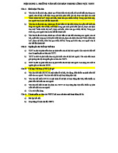
Câu Hỏi Trắc Nghiệm GDTC (Có đáp án) - Tài liệu Ôn Tập Các Nội Dung Chính
4 2 -

Quản lí vận hành máy Công nhân sản xuất hoàn thiện sản phẩm Quản lí sản xuất và chất lượng sản xuấ
15 8 -
Cảnh báo Hệ thống AI tự động kiểm tra nội dung tiêu đề dữ liệu bạn nhập Nếu sai lệ
31 16 -
hay quan l ne dsfgasdfgsdgfsdgsdg
28 14 -
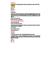
Trắc nghiệm Chương 1 & 2 Hệ Thống Thông Tin (HTTT)
34 17