Labwork report experiment 5: investigation of electromagnetic wave môn Vật lý đại cương 2 | Học viện Công Nghệ Bưu Chính Viễn Thông
The purpose of this experiment is to evaluate both qualitative and quantitative results of transmitting and receiving microwave. Tài liệu giúp bạn tham khảo, ôn tập và đạt kết quả cao. Mời đọc đón xem!
Môn: Vật lý đại cương 2 298 tài liệu
Trường: Học viện Công Nghệ Bưu Chính Viễn Thông 1.7 K tài liệu
Tác giả:


Preview text:
LABWORK REPORT
Experiment 5: Investigation of Electromagnetic Wave I. Personal Information
Verification of the Instructors - Name: Nguyen Thanh An - Student ID: 202412931 - Class: 760026 - Group 1
II. Experimental Purposes and Procedures
1. Experimental Purposes:
- The purpose of this experiment is to evaluate both qualitative and
quantitative results of transmitting and receiving microwave.
2. Experimental Procedure:
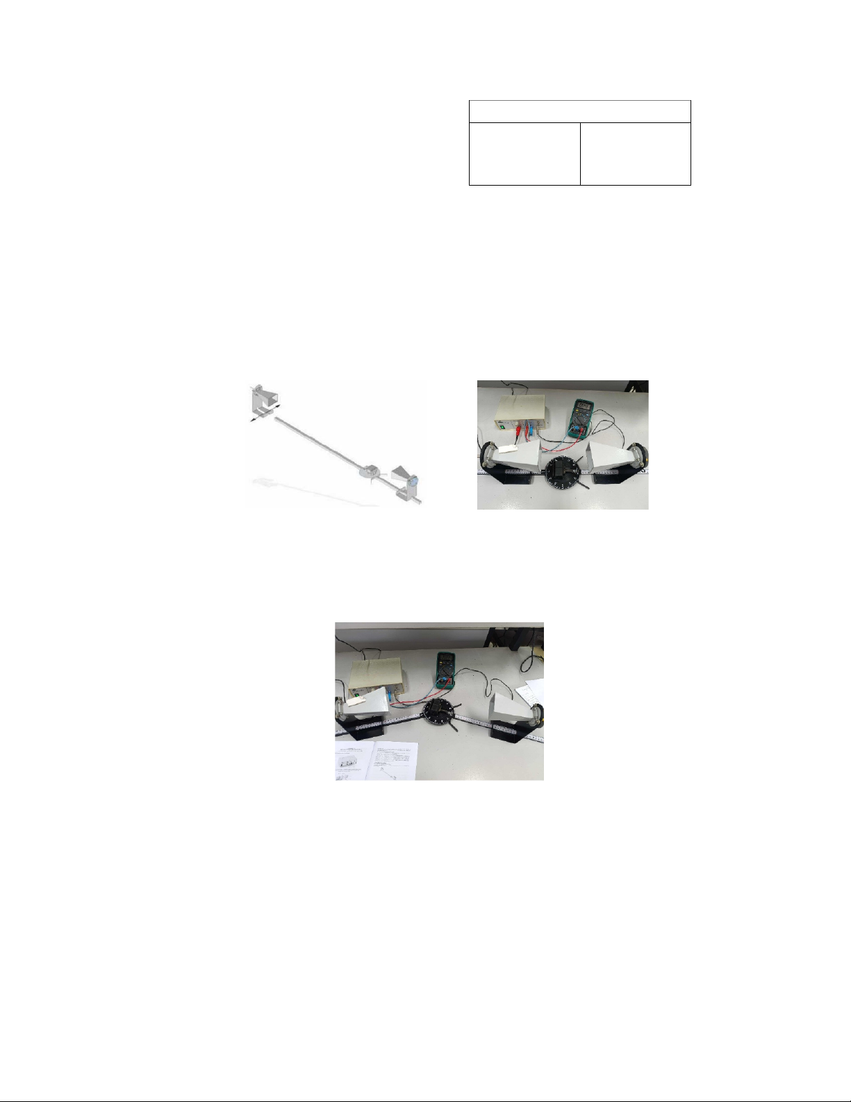
a. Straight-line propagation of microwaves
-Step 1: Set up the transmitter and receiver facing each other at the distance
of 400mm. Read the voltage shown on the digital multimeter.
- Step 2: Move the transmitter and receiver further from each other and repeat the process.
Fig. 2a.1. Experiment Setup Diagram
Fig. 2a.2. Actual Experiment
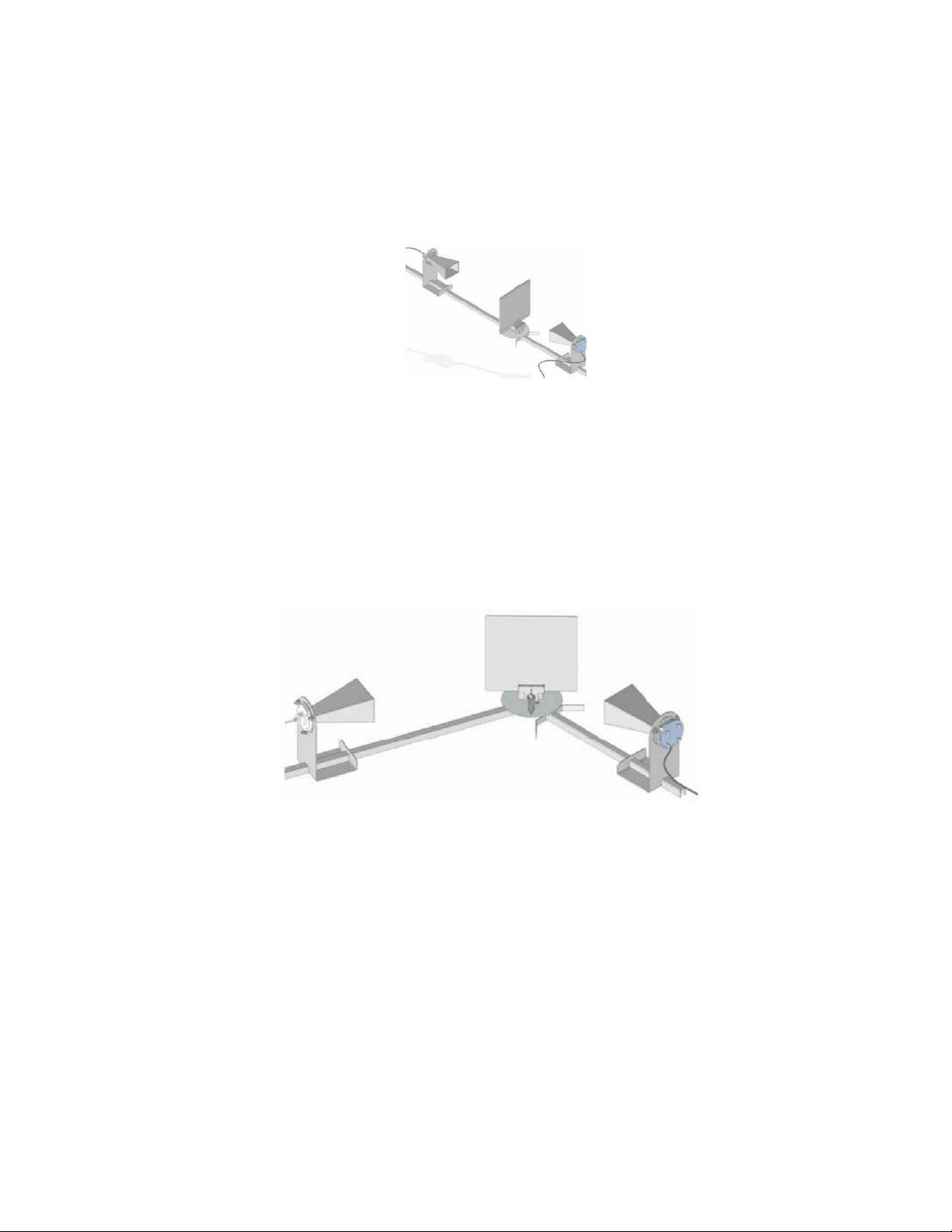
b. Angular propagation of microwaves
-Step 1: Set up the transmitter and receiver facing each other at the distance
of 600mm. Read the voltage shown on the digital multimeter.
- Step 2: Rotate the ruler axis by a 10
o angle and read the new value. Repeat until the angle reached 90 .o
Fig. 2b. Actual Experiment 1
c. Screening and absorbtion microwaves
- Step 1: Set up the transmitter and receiver facing each other at the distance of 600mm.
- Step 2: Attach the metal plate to the plate holder at the center, between the transmitter and the receiver.
- Step 3: Read the number on the digital multimeter and give conclusion.
Then change the metal plate to other obstacle plates and repeat the process.
Fig. 2c. Experiment Setup Diagram
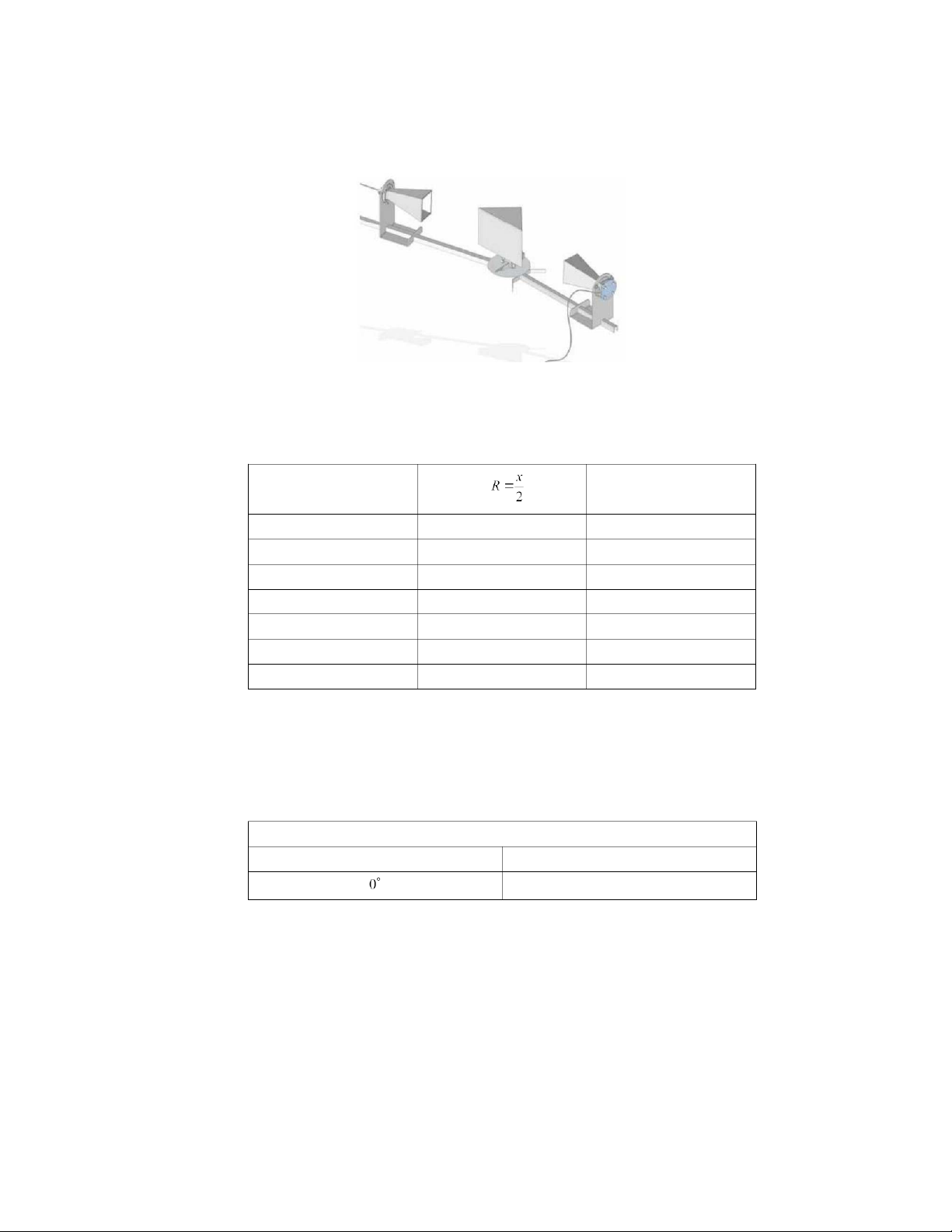
d. Reflection of microwaves
- Step 1: Setup the transmitter and receiver at and angle of incidence to be read off.
- Step 2: Line up the reflector plate at angle of approximately 30o with the
help of the pointer for the rails, which points in the direction of the normal
line (perpendicular to the mirror’s surface).
- Step 3: Change the angle of the receiver until the maximum reception is
attained. Note the angles and the reception voltage to the table. Change the
metal plate to the wooden plate and repeat the process.
Fig. 2d. Experiment Setup Diagram
e. Refraction of microwaves
- Step 1: Put the block of paraffin at the center. Points the transmitter so that
it’s perpendicular to the square edge of the paraffin block. As paraffin has 2
higher refraction index, the microwaves from the block will come out on
the hypotenuse edge of the block.
- Step 2: Rotate the receiver along the arc in correspondence to the
hypotenuse, record the values and give conclusions about the maximum
reception value of microwaves and position of the receiver.
Fig. 2e. Experiment Setup Diagram
III. Experimental Results
1. Straight-line propagation of microwaves a. Measurement Results Distance x (mm) Radius (mm) Voltage U 1 (V) 400 200 7.200 500 250 4.625 600 300 3.137 700 350 2.166 800 400 1.693 900 450 1.339 1000 500 1.088 b. Data Analysis:
- From the table, we can conclude that the magnitude of microwaves decreases as
the distance increases, given that the transmitter and receiver remained on a
straight line, facing each other.
2. Angular propagation of microwaves a. Measurement Results R = 300mm Angle Voltage U 2 (V) 1.553 3 1.364 1.166 0.428 0.145 0.028 0.016 0.015 0.012 0.011 b. Data Analysis:
- From the table, we can conclude that the magnitude of microwaves decreases as the angle increases.
3. Screening and absorption microwaves a. Measurement Results R = 300mm Object Voltage U 3 (V) Nothing 1.768 Metal plate 0.015 Wooden plate 1.087 Double – slit plate 0.745 Single – slit plate 0.385
Vertical polarization grating plate 0.018
Horizontal polarization grating plate 0.837 b. Data Analysis:
- In general, conductive materials tend to absorb microwaves, while the opposing
is true for non-conductive ones, for example, there is a big gap in microwaves
reception while the waves pass through metal and wooden plates.
- The less slit on the plate there are, the less microwaves the receiver received.
This can be concluded after comparing the figures for double and single slit plates.
- The direction of the slits also affects the passing-through ability of the
microwaves. This happens because the microwaves are magnet-electrical
waves, which is a transverse wave, so a horizontal polarization grating plate
would allow more waves to pass. 4
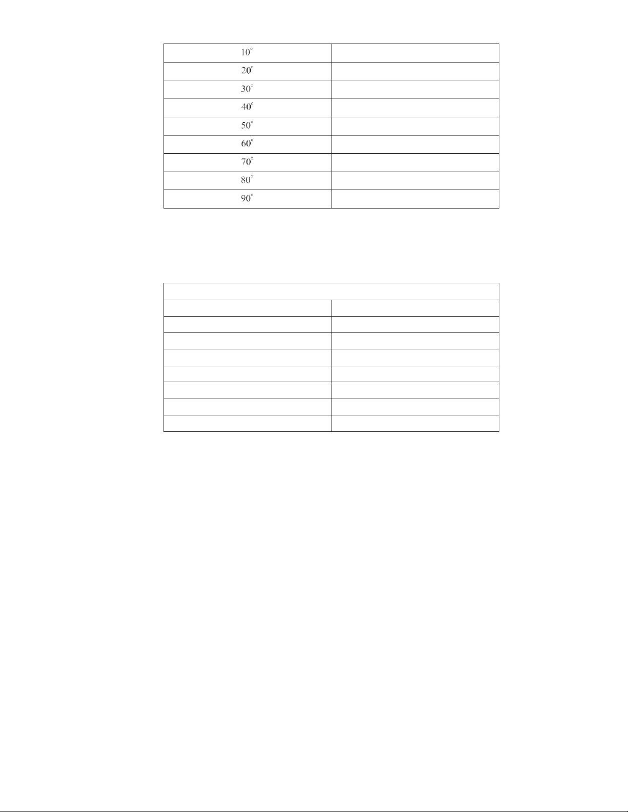
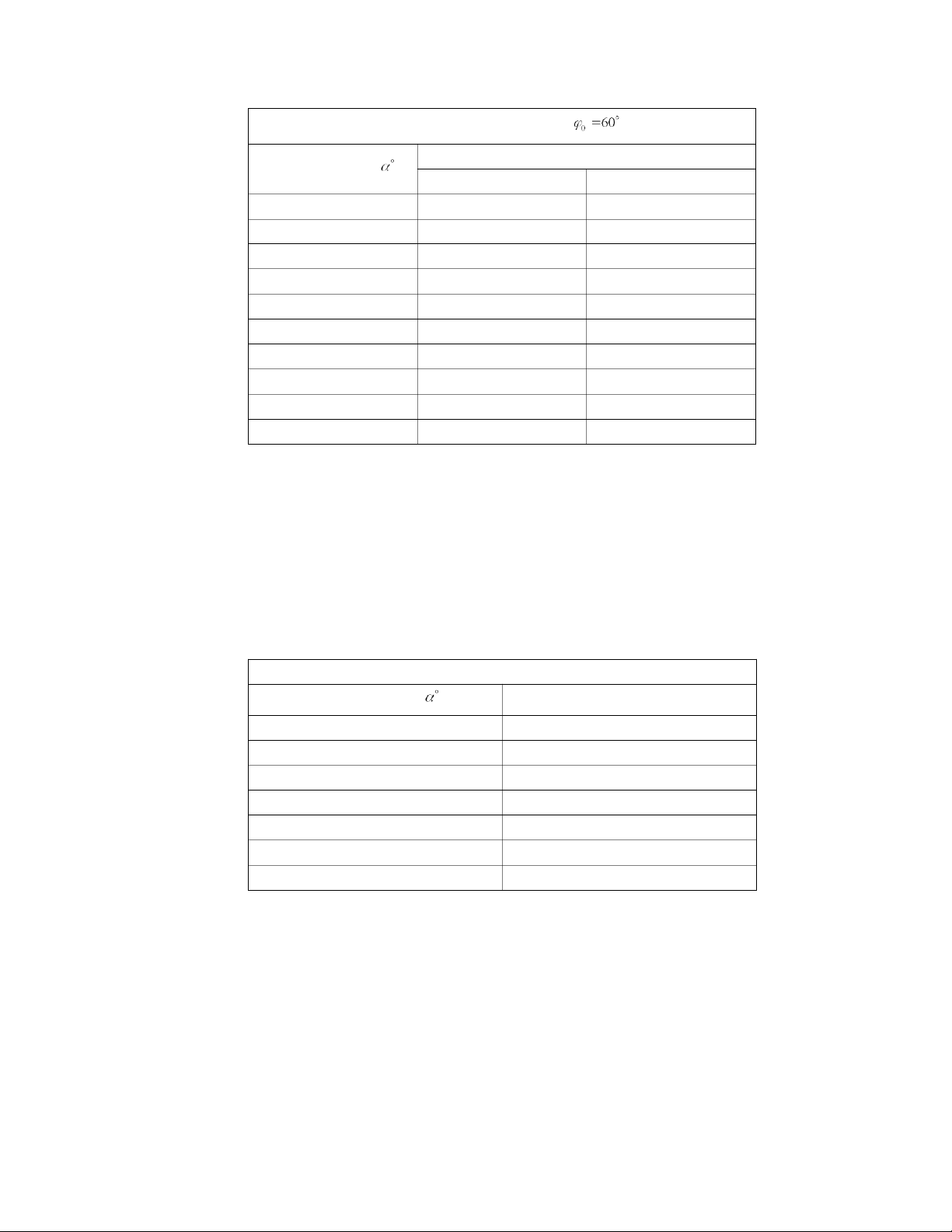
4. Reflection of microwaves a. Measurement Results
R = 300mm, Incidence Angle Voltage U 1 (V)
Reflection Angle Metal Plate Wooden Plate 90 0.750 1.220 80 0.980 0.150 70 0.330 0.300 60 1.500 0.380 50 1.330 0.110 40 0.600 0.016 30 0.180 0.020 20 0.060 0.017 10 0.020 0.013 0 0.010 0.015 b. Data Analysis
- From the experiment of screening and absorption of microwaves above, we
know that metal blocks the waves, while microwaves can penetrate wooden
plates. It’s also shown here, the figures recorded with a wooden plate is lower than metal ones.
- Looking at the table, we can see that the data follows a trend of increasing, up
to its peak at 60 degrees, which is equal to the incidence angle, then gradually
decreases to near zero at 0 degree, which is coincided with the normal line perpendicular to the plate.
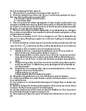
5. Refraction of microwaves a. Measurement Results R = 300mm
Refraction Angle Voltage U 1 (V) 0 0.283 5 0.598 10 0.521 15 0.071 20 0.863 30 1.370 35 1.036 5 40 0.745 b. Data Analysis
- From the table, we can see that the maximum value is received at 30 degrees.
This deviation happens as paraffin has higher refractive index than air (~1.46 –
1.48), so the microwaves passing through the paraffin wax is “bent” towards the
hypotenuse of the block. Previously, there is a slight rise then decrease at about
5-10 degrees, but it is not the highest number recorded, and this comes from the
uncertainty in the device, as some waves may travel alongside the paraffin, not through the block. 6
Tài liệu liên quan:
-
Bài tập Vật lý nguyên tử môn Vật lý đại cương 2 | Học viện Công Nghệ Bưu Chính Viễn Thông
11 6 -
Bài tập Vật lý nguyên tử môn Vật lý đại cương 2 | Học viện Công Nghệ Bưu Chính Viễn Thông
12 6 -

Tán xạ ánh sáng và Hiệu ứng Tyndall - Lý thuyết và Ứng dụng môn Vật lý đại cương 2 | Học viện Công Nghệ Bưu Chính Viễn Thông
20 10 -

Chương 23: Quang học lượng tử môn Vật lý đại cương 2 | Học viện Công Nghệ Bưu Chính Viễn Thông
18 9 -

Chương 24: Cơ Học Lượng Tử - Tính Sóng-Hạt và Phương Trình Schrödinger môn Vật lý đại cương 2 | Học viện Công Nghệ Bưu Chính Viễn Thông
19 10