Physics formulas môn Vật lý đại cương 2 | Học viện Công Nghệ Bưu Chính Viễn Thông
The descriptions above, impedance is used as an example.Rectangular and Polar Notation can also be used to express amperage, voltage, and power . Tài liệu giúp bạn tham khảo, ôn tập và đạt kết quả cao. Mời đọc đón xem!
Môn: Vật lý đại cương 2 296 tài liệu
Trường: Học viện Công Nghệ Bưu Chính Viễn Thông 1.5 K tài liệu
Tác giả:


Preview text:
PHYSICS FORMULAS Electron =-1.602 19 × 10-19 C =9.11 × 10⁻³¹ kg Rectangular Notation: Z R jX where +j represents Proton =1.602 19 × 10-19 C =1.67 × 10⁻²⁷ kg
inductive reactance and -j represents capacitive reactance. Neutron =0 C =1.67 × 10⁻²⁷ kg 8
6 means that a resistor of 8 is
6.022 × 10²³ atoms in one atomic mass unit For example, Zj
in series with an inductive reactance of 6 .
e is the elementary charge: 1.602 19 × 10 Polar Notation: Z = M
, where M is the magnitude of the -19 C
Potential Energy, velocity of electron: PE = eV = ½mv2
reactance and is the direction with respect to the ho 4 ri zio n nsta erli ( e p s ur w e it r h e s a is c taapnacei) t oarx is wi.t hF o a r e e x acatm anpcle e , o a f r 3esi st wor u o l f 1V d 1 a = m 1 p J =/ C 6.21 ×1 N 1 / 0 C 18 = el e1 c V tr / o m ns/seco1 nJd = 1 N C ·om ul = o 1 mb /C s · e V cond be expressed as 5 -36.9° . 1 hp = 0.756 kW 1 N = 1 T·A·m 1 Pa = 1 N/m2
Power = Joules/second = I2R = IV [watts W] Equation: xb b ac
In the descriptions above, impedance is used as an example. 22
Rectangular and Polar Notation can also be used to Quadratic Kine KEtic E 1 nerg mvy [J]
express amperage, voltage, and power. 24 2 [Natural Log: when e
To convert from rectangular to polar notation: b = x, lna x = b ] Given:
X - jY(careful with the sign before the ”j”) m: 10-3 : 10-6 n: 10-9 p: 10-12 f: 10-15 a: 10-18 Magnitude: XY2M 2 Angle: tan Y (negative sign carried over Addition of Multiple Vectors: X from rectangular notation r r r r in this example) R A B C
Note: Due to the way the calculator works, if X is negative, r r r r Re xs-uclt o an m tp = on S e u ntm of thAex vceocstAors
you must add 180° after taking the inverse tangent. If the R A B C r r r r y-component Ay si A n
result is greater than 180°, you may optionally subtract x x x x R A B C
360° to obtain the value closest to the reference angle. Given: M y y y y
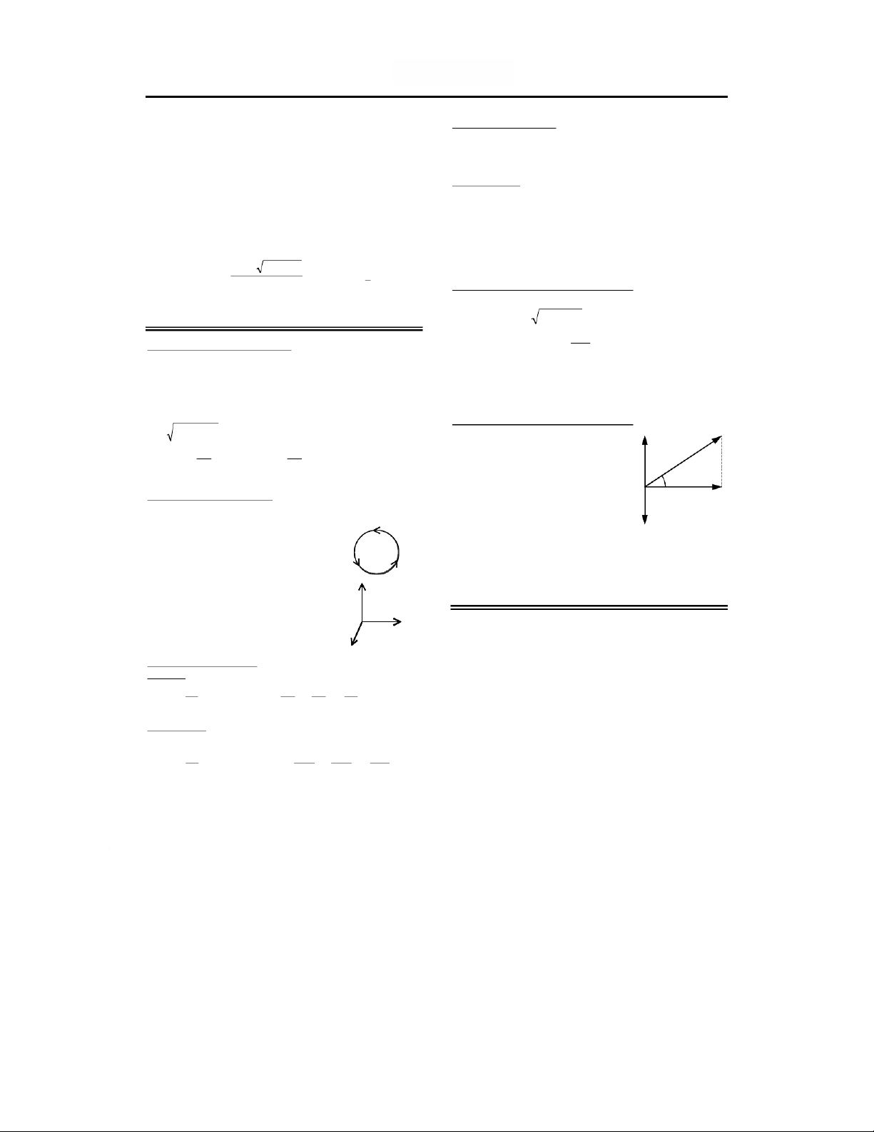
To convert from polar to rectangular (j) notation: R R 2 R 2 Magnitude (length) of R X Value: Mcos R x y tan 1 or tan R R R Angle of the resultant Y (j) Value: Msin M y y R R Magnitude Y x x Multiplication of Vectors: In cosn a ve m r e siogns , a tsh teh je va lvuael w ue il f lo h r av n e g lth ese X Positive direction:
Cross Product or Vector Product: having a magnitude < 180°. i
Use rectangular notation when adding and subtracting. i j k j i k 0
Use polar notation for multiplication and division. Multiply in i i
polar notation by multiplying the magnitudes and adding jk
the angles. Divide in polar notation by dividing the Dot Product or Scalar Product:
magnitudes and subtracting the denominator angle from j the numerator angle. 0 1 ab i j i i ab cos i k Derivative of xVecto y rs:zdx
Velocity is the derivative of position with respect to time: v k ijk d ( ij ) dy dz dt dt dt dt Acceleration is v the de v rivativ v e of veloc dv ity with respect to time: a k ijk d ( ij ) dv dv xyz dt dt dt dt x y z
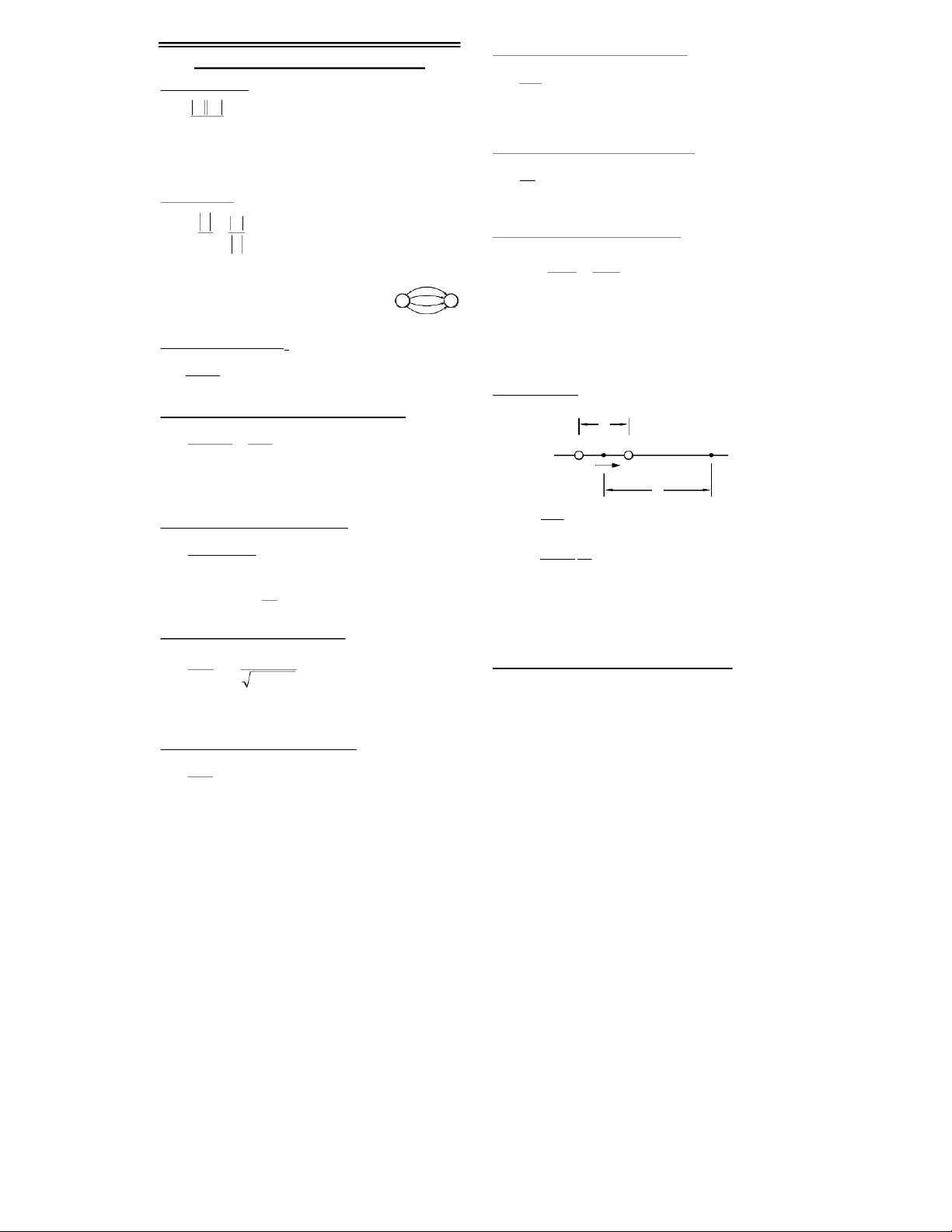
Electric Field inside a spherical shell: [N/C] ELECTRIC CHARGES AND FIELDS Ekqr E = electric field [N/C] Coulomb's Law: 3 [Newtons N] R q = charge [C]
r = distance from center of sphere to Fkq q 1 2
where: F = force on one charge by the charge [m] 2 the other[N] r k = 8.99 × 10 R 9 [N·m2/C2] = radius of the sphere [m] q1 = charge [C]
Electric Field outside a spherical shell: [N/C] q2 = charge [C] r E = distance [m] Ekq = electric field [N/C] 2 q = charge [C]
Electric Field: [Newtons/Coulomb or Volts/Meter] r
r = distance from center of sphere to the charge [m] Ekq F
where: E = electric field [N/C or V/m] k = 8.99 × 10⁹ [N·m2/C2]
Average Power per unit area of an electric or r 2 q q = charge [C] magnetic field: r = distance [m] WmE 2 2 W = watts m m Bc F = force /2 Em = max. electric field [N/C] 2 0 2 c 0 0 = 4 × 10⁻⁷
Electric field lines radiate outward from +- c = 2.99792 × 10⁸ [m/s]
positive charges. The electric field Bm = max. magnetic field [T] is zero inside a conductor.
A positive charge moving in the same direction as the electric Relationship of k to 0:
field direction loses potential energy since the potential of
the electric field diminishes in this direction. where: k = 8.99 × 10 k 1 9 [N·m2/C2]
Equipotential lines cross EF lines at right angles. 0 = permittivity of free space 40 8.85 × 10⁻¹² [C2/N·m2]
Electric Dipole: Two charges of equal magnitude and
opposite polarity separated by a distance d.
Electric Field due to an Infinite Line of Charge: [N/C] d 2k E = electric field [N/C] Er
= charge per unit length [C/m} -Q +Q 2 0 r 0 = permittivity of free space 8.85 × 10 p -12 [C2/N·m2] r = distance [m] z k = 8.99 × 10⁹ [N·m2/C2] Ek 2 p E = electric field [N/C]
Electric Field due to ring of Charge: [N/C] z3 k = 8.99 × 10⁹ [N·m2/C2]
0 = permittivity of free space 8.85 × Ekqz ( E = electric field [N/C] 1 2 2 )3/2 p 10 k -12 C2/N·m2 = 8.99 × 10 N·m zR 9 [ 2/C2] Ez 3
p = qd [C·m] "electric dipole moment" q = charge [C] 20 in the direction negative to z or if z >> R, Ekq = distance to the charge [m] positive 2 when z » d R = radius of the ring [m] z
z = distance [m] from the dipole center to the point along the
Electric Field due to a disk Charge: [N/C]
dipole axis where the electric field is to be measured Ez E = electric field [N/C] 21 = charge per unit area
Deflection of a Particle in an Electric Field: 02 2 zR [C/m2} ymv qEL y = deflection [m] 0 = 8.85 × 10⁻¹² [C 2 2/N·m2] 2 2 m = mass of the particle [kg] z = distance to charge [m] d = plate separation [m] R = radius of the ring [m] v = speed [m/s]
Electric Field due to an infinite sheet: [N/C] q = charge [C] E = electric field [N/C or V/m E E = electric field [N/C] L = length of plates [m] = charge per unit area [C/m2} 20 0 = 8.85 × 10⁻¹² [C2/N·m2]
Potential Difference between two Points: [volts V] Gauss' Law: 0 = 8.85 × 10⁻¹² [C2/N·m2] PE PE = work to move a charge 0 qenc
is the rate of flow of an electric V V B V A qEd from A to B [N·m or J] field [N·m2/C] q = charge [C] 0EA d qenc
qenc = charge within the gaussian VB = potential at B [V] surface [C] VA = potential at A [V] integral over a closed surface E = electric field [N/C or V/m d = plate separation [m]
E is the electric field vector [J]
Electric Potential due to a Point Charge: [volts V]
A is the area vector [m2] pointing V outward normal to the surface. q = potential [volts V] V k k = 8.99 × 10 r 9 [N·m2/C2] q = charge [C] CAPACITANCE r = distance [m]
Potential Energy of a Pair of Charges: [J, N·m or Parallel-Plate Capacitor: C·V] 0C = ca A C pacitance [farads F] PE qVkq 2 1 q 1 2
V 1 is the electric potential due to d = the dielectric constant (1) q1 at a point P r 0 = permittivity of free space
q2 V1 is the work required to bring 8.85 × 10⁻¹² C2/N·m2 q2 from infinity to point P A = area of one plate [m2] Work and Potential:
d = separation between plates [m] U U
U = electric potential energy [J] f U i W Cylindrical Capacitor: W = work done on a particle by UW a field [J] CL C = capacitance [farads F] = dielectric constant (1) W = work done on a particle 20 ln( /) WFdFdcos brought from infinity (zero b a 0 = 8.85 × 10⁻¹² C2/N·m2 f potential) to its present L = length [m] Wq d Es location [J] b = radius of the outer F = is the force vector [N] conductor [m] i
d = is the distance vector over a = radius of the inner V V V W which the force is conductor [m] f i applied[m] q F = is the force scalar [N] Spherical Capacitor: d C = capacitance [farads F] f = is the distance scalar [m] Cab Es = is the angle between the 4 = dielectric constant (1) Vd 0 force and distance vectors b a 0 = 8.85 × 10⁻¹² C2/N·m2 i
ds = differential displacement of b = radius, outer conductor the charge [m] [m] V = volts [V]
a = radius, inner conductor [m] q = charge [C]
Maximum Charge on a Capacitor: [Coulombs C]
Flux: the rate of flow (of an electric field) Q VC [N·m Q = Coulombs [C] 2/C] V = volts [V] EA d
is the rate of flow of an electric C = capacitance in farads [F] field [N·m2/C] integral over a closed surface
For capacitors connected in series, the charge Q is equal for (cos E ) dA
each capacitor as well as for the total equivalent. If the
dielectric constant is changed, the capacitance is
E is the electric field vector [N/C]
multiplied by , the voltage is divided by , and Q is
A is the area vector [m2] pointing outward normal to the surface.
unchanged. In a vacuum = 1, When dielectrics are used, replace 0 with 0.
Electrical Energy Stored in a Capacitor: [Joules J] UQV CV Q 22U = Potential Energy [J] E Q = Coulombs [C] 2 2 2 C V = volts [V] C = capacitance in farads [F] Charge per unit Area: [C/m2] Resistivity: [Ohm Meters] q = charge per unit area [C/m2] E = resistivity [ · m] A q = charge [C] E = electric field [N/C] A = area [m J 2] J = current density [A/m RA 2] Energy Density: R (in a vacuum) [J/m = resistance [ ohms] 3] L A = area [m2] uE 1
2u = energy per unit volume [J/m3] 20 L = length of conductor [m] 0 = permittivity of free space 8.85 × 10⁻¹² C2/N·m2
Variation of Resistance with Temperature: E = energy [J] T T ( ) = resistivity [ · m] 0 0 0
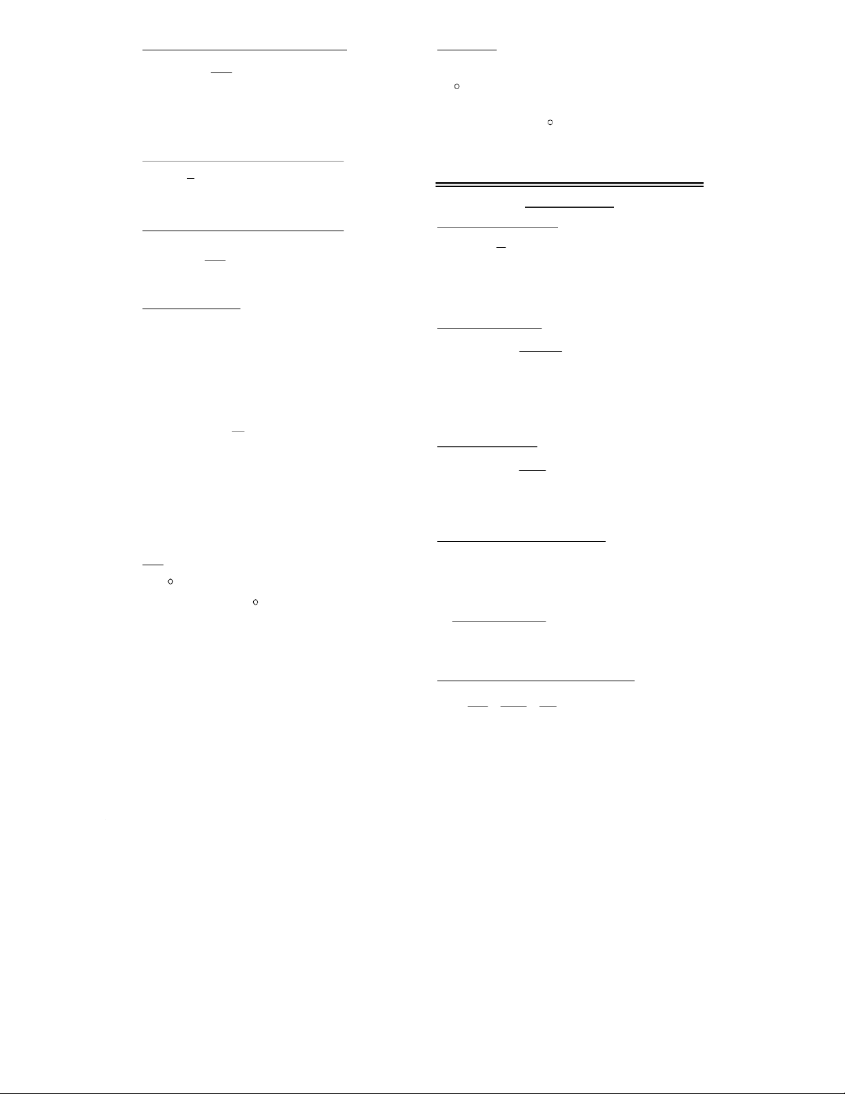
= reference resistivity [ · m] = temperature coefficient of Capacitors in Series: Capacitors in Parallel: resistivity [K-1] 1 1 1 ... C 1 2 ... T eff C C 0 = reference temperature C
T - T0 = temperature difference 1 C 2C eff [K or °C]
Capacitors connected in series all have the same charge q.
For parallel capacitors the total q is equal to the sum of the CURRENT charge on each capacitor. Time Constant: [seconds] Current Density: [A/m2] RC
= time it takes the capacitor to reach 63.2% id JA i = current [A]
of its maximum charge [seconds] J = current density [A/m R = series resistance [ohms ] 2] if current is uniform A = area [m2] C = capacitance [farads F] and parallel to dA, L = length of conductor [m]
Charge or Voltage after t Seconds: then: i JA [coulombs C] e = charge per carrier
ne = carrier charge density [C/m charging: q = charge after t seconds 3] Jne V ( )d qQe [coulombs C] Vd = drift speed [m/s] t 1/ Q = maximum charge [coulombs C] Q = CV
Rate of Change of Chemical Energy in a Battery: V V e t 1/ S e = natural log Pi P = power [W] discharging: t = time [seconds] i = current [A] qQe / = time constant RC [seconds] t = emf potential [V] V = volts [V] V V / t V S e S = supply volts [V]
[Natural Log: when eb = x, ln x = b ] Kirchhoff’s Rules Drift Speed:
1. The sum of the currents entering a junctions is equal to
Q = # of carriers × charge/carrier IQ
the sum of the currents leaving the junction. t = time in seconds tnqv A
2. The sum of the potential differences across all the d n = # of carriers
elements around a closed loop must be zero. q = charge on each carrier v
Evaluating Circuits Using Kirchhoff’s Rules
d = drift speed in meters/second
A = cross-sectional area in meters2
1. Assign current variables and direction of flow to all
branches of the circuit. If your choice of direction is
incorrect, the result will be a negative number. Derive RESISTANCE
equation(s) for these currents based on the rule that
currents entering a junction equal currents exiting the
Emf: A voltage source which can provide continuous current junction. [volts]
2. Apply Kirchhoff’s loop rule in creating equations for IR Ir
= emf open-circuit voltage of the battery
different current paths in the circuit. For a current path
beginning and ending at the same point, the sum of I = current [amps]
voltage drops/gains is zero. When evaluating a loop in the R = load resistance [ohms]
direction of current flow, resistances will cause drops
r = internal battery resistance [ohms]
(negatives); voltage sources will cause rises (positives)
provided they are crossed negative to positive—otherwise they will be drops as well.
3. The number of equations should equal the number of
variables. Solve the equations simultaneously.
Charged Particle in a Magnetic Field: r = radius of rotational path MAGNETISM rmv m = mass [kg] qB v = velocity [m/s]
André-Marie Ampére is credited with the discovery of q = charge [C]
electromagnetism, the relationship between electric B = magnetic field [T] currents and magnetic fields.
Heinrich Hertz was the first to generate and detect
Magnetic Field Around a Wire: [T]
electromagnetic waves in the laboratory. BI B = magnetic field [T] 0 = the permeability of free
Magnetic Force acting on a charge q: [Newtons N] 2 r space 4 ×10⁻⁷ T·m/A I = current [A] FqvB sin F = force [N] q = charge [C]
r = distance from the center of Fq vB the conductor v = velocity [m/s] B = magnetic field [T]
Magnetic Field at the center of an Arc: [T] = angle between v and B Bi B = magnetic field [T] 0 = the permeability of free
Right-Hand Rule: Fingers represent the direction of the 4 r space 4 ×10⁻⁷ T·m/A
magnetic force B, thumb represents the direction of v (at
any angle to B), and the force F on a positive charge i = current [A] = the arc in radians
emanates from the palm. The direction of a magnetic field
is from north to south. Use the left hand for a negative
r = distance from the center of charge. the conductor
Also, if a wire is grasped in the right hand with the thumb in
Hall Effect: Voltage across the width of a
the direction of current flow, the fingers will curl in the
direction of the magnetic field.
conducting ribbon due to a Magnetic Field:
In a solenoid with current flowing in the direction of curled ( ne)VhBi
ne = carrier charge density [C/m3]
fingers, the magnetic field is in the direction of the thumb. w V
When applied to electrical flow caused by a changing
w = voltage across the width [V]
h = thickness of the conductor [m]
magnetic field, things get more complicated. Consider the vBw dw V B = magnetic field [T]
north pole of a magnet moving toward a loop of wire i = current [A]
(magnetic field increasing). The thumb represents the
north pole of the magnet, the fingers suggest current flow in vd = drift velocity [m/s]
the loop. However, electrical activity will serve to balance w = width [m]
the change in the magnetic field, so that current will
Force Between Two Conductors: The force is
actually flow in the opposite direction. If the magnet was
attractive if the currents are in the same direction.
being withdrawn, then the suggested current flow would be F = force [N]
decreasing so that the actual current flow would be in the FI1 I 0 1 2
direction of the fingers in this case to oppose the decrease. l = length [m] l 2
Now consider a cylindrical area of magnetic field going into d = the permeability of free
a page. With the thumb pointing into the page, this would space 4 ×10⁻⁷ T·m/A
suggest an electric field orbiting in a clockwise direction. If I = current [A]
the magnetic field was increasing, the actual electric field
d = distance center to center [m]
would be CCW in opposition to the increase. An electron in
the field would travel opposite the field direction (CW) and
Magnetic Field Inside of a Solenoid: [Teslas T]
would experience a negative change in potential. BnI B = magnetic field [T] 0 = the permeability of free
Force on a Wire in a Magnetic Field: [Newtons N] space 4 ×10⁻⁷ T·m/A FBI lsin F = force [N]
n = number of turns of wire per B = magnetic field [T] unit length [#/m] FIB l I = amperage [A] I = current [A] l = length [m] = angle between B and the Magnetic Dipole Moment: [J/T] direction of the current
NiA = the magnetic dipole moment [J/T] N = number of turns of wire
Torque on a Rectangular Loop: [Newton·meters N·m] i = current [A] NBIA sin N = number of turns A = area [m2] B = magnetic field [T] I = amperage [A]
Magnetic Flux through a closed loop: [T·M2 or Webers] A = area [m2] BAcos B = magnetic field [T] = angle between B and the A = area of loop [m2] plane of the loop = angle between B and the perpen-dicular to the plane of the loop
Magnetic Flux for a changing magnetic field: [T·M2 or Amperes' Law: Webers] B di s B = magnetic field [T] enc 0 BA d B = magnetic field [T]
= the permeability of free space A = area of loop [m2] 4 ×10⁻⁷ T·m/A
ienc = current encircled by the loop[A]
A Cylindrical Changing Magnetic Field
Joseph Henry, American physicist, made improvements E d sErd B 2 E = electric field [N/C] to the electromagnet. dt r = radius [m]
James Clerk Maxwell provided a theory showing the t = time [s]
close relationship between electric and magnetic BBA B r2 = magnetic flux [T·m2 or
phenomena and predicted that electric and magnetic Webers] d AdB
fields could move through space as waves. B = magnetic field [T]
J. J. Thompson is credited with the discovery of the dt dt A = area of magnetic field [m electron in 1897. 2] Nd dB/dt = rate of change of dt the magnetic field [T/s] = potential [V] INDUCTIVE & RCL CIRCUITS N = number of orbits Inductance of a Coil: [H]
Faraday’s Law of Induction states that the instan- LN N = number of turns = magnetic flux [T·m2]
taneous emf induced in a circuit equals the rate of
change of magnetic flux through the circuit. Michael I I = current [A]
Faraday made fundamental discoveries in
In an RL Circuit, after one time constant ( = L/R) the
magnetism, electricity, and light.
current in the circuit is 63.2% of its final value, /R. N = number of turns Nt = magnetic flux [T·m2] RL Circuit: t = time [s] current rise: UB = Potential Energy [J]
Lenz’s Law states that the polarity of the induced emf is IV V = volts [V] 1
such that it produces a current whose magnetic field / etL R = resistance [ ] R
opposes the change in magnetic flux through a circuit e = natural log current decay: t = time [seconds]
Motional emf is induced when a conducting bar moves
L = inductive time constant L/R IV
through a perpendicular magnetic field. / etL [s] Blv B = magnetic field [T] R I = current [A] l = length of the bar [m] v = speed of the bar [m/s]
Magnetic Energy Stored in an Inductor:
emf Induced in a Rotating Coil: ULI B 1 2UB = Potential Energy [J] 2 L = inductance [H] NAB sin t N = number of turns A = area of loop [m I = current [A] 2] B = magnetic field [T]
Electrical Energy Stored in a Capacitor: = angular velocity [rad/s] [Joules J] t = time [s] UQV CV Q 22UE = Potential Energy [J] E Q = Coulombs [C]
Self-Induced emf in a Coil due to changing current: 2 2 2C V = volts [V] LI L = inductance [H] C = capacitance in farads [F] I = current [A] t t = time [s]
Resonant Frequency: : The frequency at which XL = XC.
In a series-resonant circuit, the impedance is at its
Inductance per unit length near the center of a solenoid:
minimum and the current is at its maximum. For a LnA L = inductance [H]
parallel-resonant circuit, the opposite is true. l 0 2 l = length of the solenoid [m]
= the permeability of free space R 1 fR = Resonant Frequency [Hz] fLC L = inductance [H] 4 ×10⁻⁷ T·m/A 2 C = capacitance in farads [F]
n = number of turns of wire per unit 1 = angular frequency [rad/s] length [#/m] A = area [m2] LC Voltage, series circuits: [V]
Damped Oscillations in an RCL Series Circuit: Vq C VIR
VC = voltage across capacitor [V] qQe t Rt L /cos( 2 ) q = charge on capacitor [C] C R q = charge on capacitor [C] Q = maximum charge [C] V V fR = Resonant Frequency [Hz] where e = natural log X R RI L = inductance [H] R = resistance [ ] 2 2 X C = capacitance in farads [F] RL (/) 2 L = inductance [H] R = resistance [ ] = angular frequency of the V V 2 2 2 R V X I = current [A] 1/LC undamped oscillations V = supply voltage [V] [rad/s] V When R is small and
X = voltage across reactance [V] = angular frequency of the
VR = voltage across resistor [V] damped oscillations UQ 2 [rad/s]
Phase Angle of a series RL or RC circuit: / [degrees] eRt L 2 C U = Potential Energy of the tan X V capacitor [J] X = Phase Angle [degrees] R V X = reactance [ ] C = capacitance in farads [F] R R = resistance [ ] Parallel RCL Circuits: cos VR R V = supply voltage [V] I V Z
VX = voltage across reactance [V] C 2 2 ( would be negative
VR = voltage across resistor [V] I I ( I)I TRCL R I in a capacitive circuit) Z = impedance [ ]
Impedance of a series RL or RC circuit: V [ ] tan I ICL Z 2 2 R 2 X = Phase Angle [degrees] IR IL E I Z X = reactance [ ] Z X R R = resistance [ ]
To find total current and phase angle in multielement circuits, C V = supply voltage [V]
find I for each path and add vectorally. Note that when V V V CR
VX = voltage across reactance [V]
converting between current and resistance, a division will ZR X j
VX = voltage across resistor [V]
take place requiring the use of polar notation and resulting Z = impedance [ ]
in a change of sign for the angle since it will be divided into
(subtracted from) an angle of zero. Series RCL Circuits:
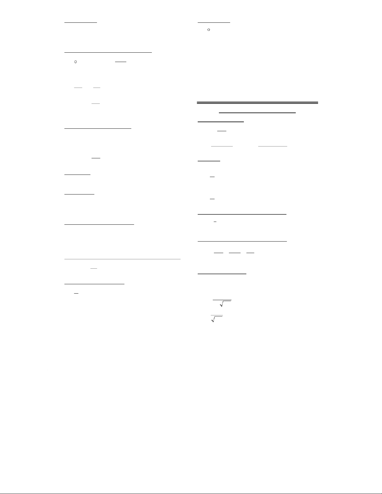
Equivalent Series Circuit: Given the Z in polar notation of a XL
parallel circuit, the resistance and reactance of the The Resultant Phasor X X X is LC
equivalent series circuit is as follows:
in the direction of the larger reactance R RZT cos XZT sin
and determines whether the circuit is inductive or capacitive. If X L is larger I
than X C, then the circuit is inductive
and X is a vector in the upward X AC CIRCUITS C direction.
Instantaneous Voltage of a Sine Wave:
In series circuits, the amperage is the VL
reference (horizontal) vector. This is V V max sin f 2 V = voltage [V] t f = frequency [H
observed on the oscilloscope by z] t = time [s]
looking at the voltage across the R V
resistor. The two vector diagrams at I Maximum and rms Values:
right illustrate the phase relationship I = current [A]
between voltage, resistance, reactance, IIm2 VVm 2 V = voltage [V] and amperage. C V Series RCL Impedance ZR X X 2 2 ( 2) ZR cos RLC Circuits: LC V V 2 2 ( ) ZR X X 2 2 RLC V V ( )
Impedance may be found by adding the components using LC
vector algebra. By converting the result to polar notation, cos tan X X LCPIV avg the phase angle is also found. R PF cos
For multielement circuits, total each resistance and reactance
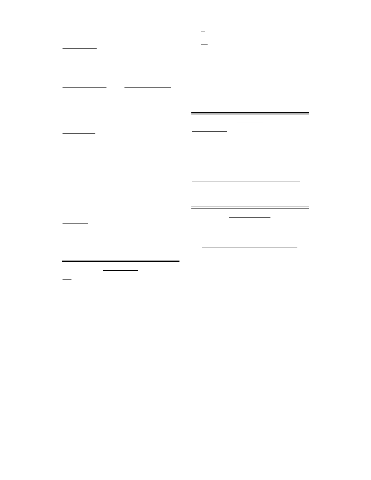
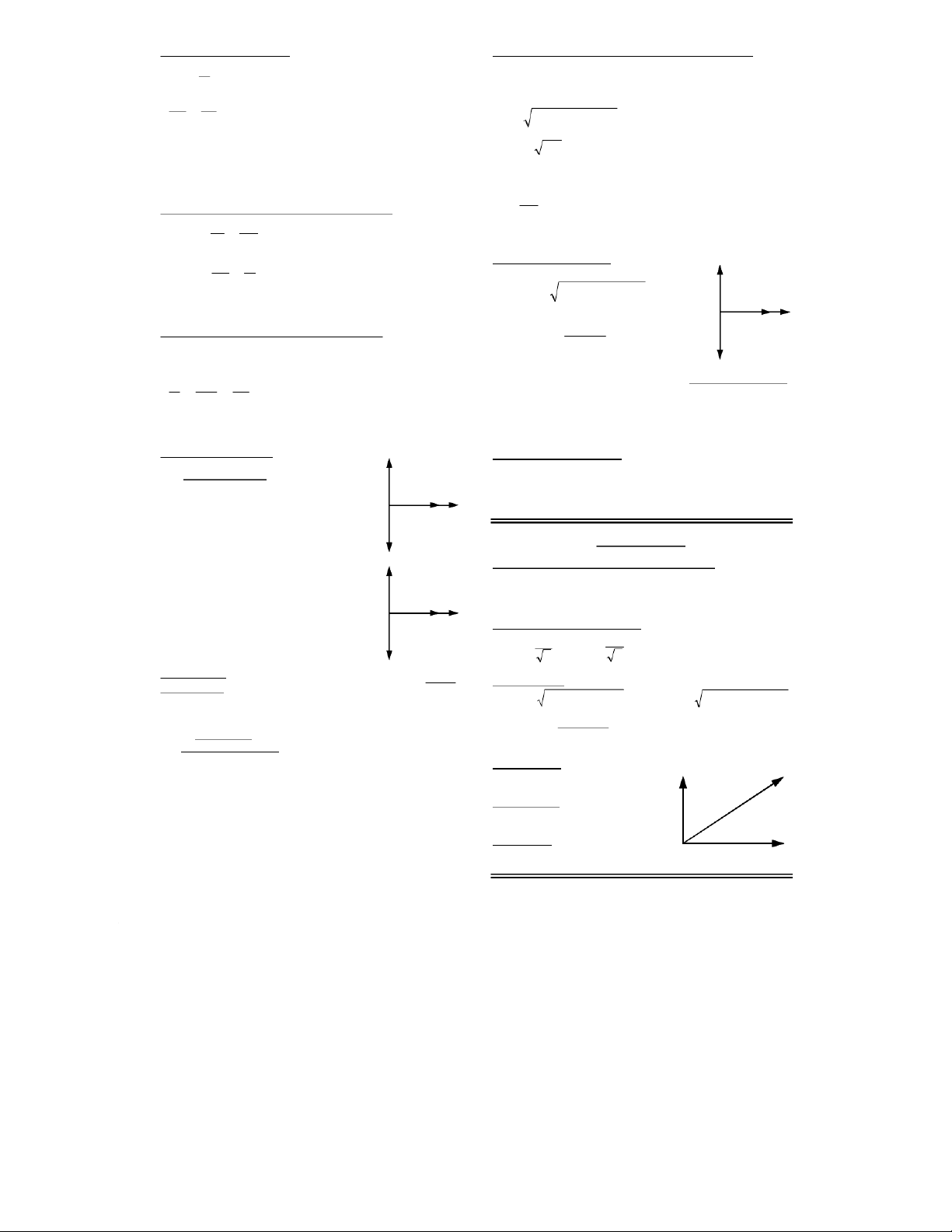
before using the above formula. Conductance (G): The reciprocal of resistance in B Y siemens (S). Susceptance (B, BL, BC): The reciprocal of reactance in Admittance siemens (S). Admittance G (Y): The reciprocal Susceptance of impedance in siemens (S). Conductance ELECTROMAGNETICS Poynting Vector [watts/m2]: = the permeability of free WAVELENGTH SEB E 1 1 2 space 4 ×10⁻⁷ T·m/A
E = electric field [N/C or V/M] c = speed of light 2.998 × 10 0 0 8 m/s B = magnetic field [T] = wavelength [m] cB E c = 2.99792 × 10⁸ [m/s] c f f = frequency [Hz] c/ E B E = electric field [N/C] B = magnetic field [T] LIGHT 1Å = 10-10m
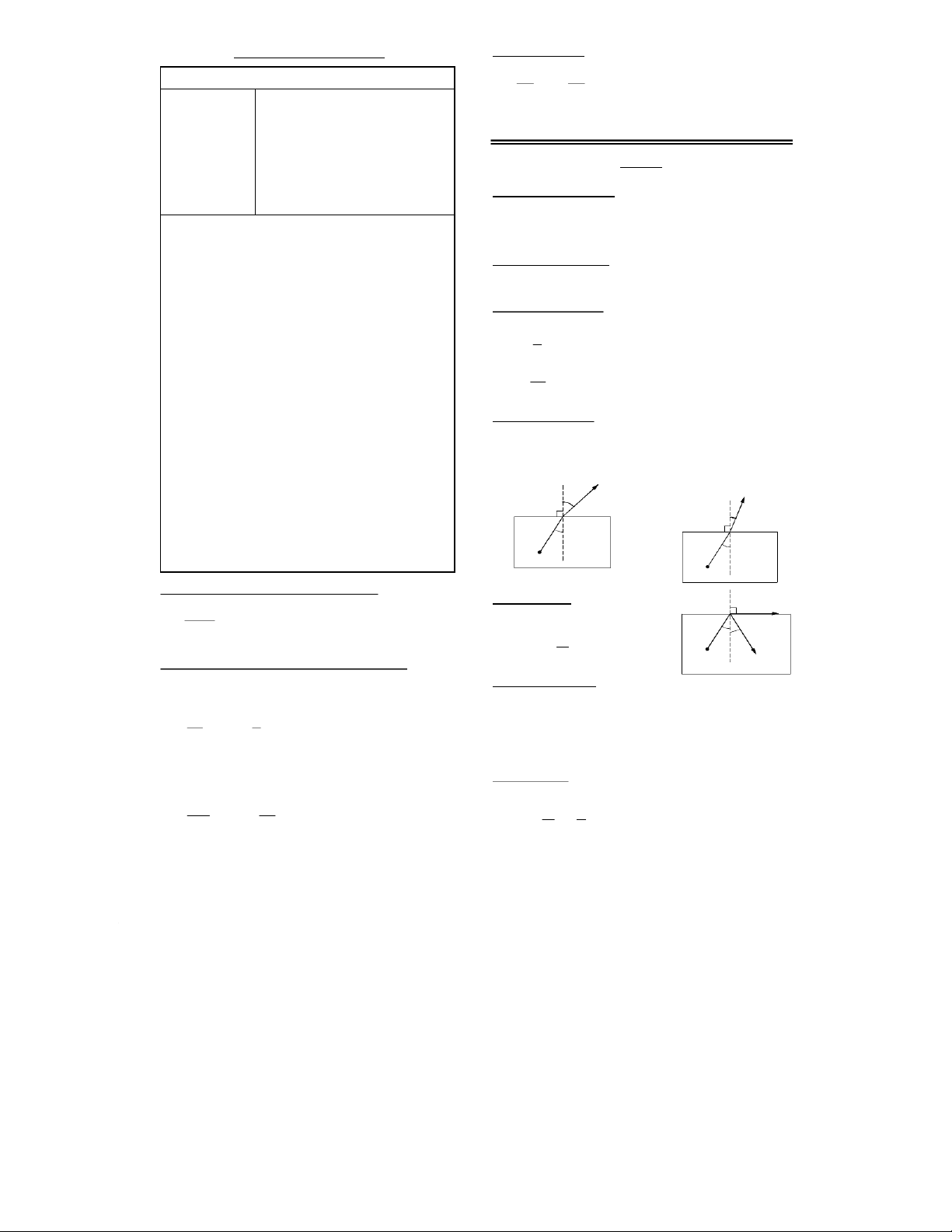
Å = (angstrom) unit of wavelength equal to 10-10 m Indices of Refraction: Quartz: 1.458 m = (meters) Glass, crown 1.52 Glass, flint 1.66 WAVELENGTH SPECTRUM Water 1.333 BAND METERS ANGSTROMS Air 1.000 293 Longwave radio 1 - 100 km 1013 - 1015
Angle of Incidence: The angle measured from the Standard Broadcast 100 - 1000 m 10
perpendicular to the face or from the perpendicular to the 12 - 1013 tangent to the face Shortwave radio 10 - 100 m 1011 - 1012
Index of Refraction: Materials of greater density have TV, FM 0.1 - 10 m 109 - 1011 a higher index of refraction. Microwave 1 - 100 mm 107 - 109 nc n = index of refraction
c = speed of light in a vacuum 3 × 10⁸ m/s Infrared light 0.8 - 1000 m8000 - 107 v
v = speed of light in the material [m/s] Visible light 360 - 690 nm 3600 - 6900 n 0
= wavelength of the light in a vacuum [m] violet 360 nm 3600
= its wavelength in the material [m] n blue 430 nm 4300
Law of Refraction: Snell’s Law green 490 nm 4900 n sin sin n = index of refraction 1n 1 2 2 = angle of incidence yellow 560 nm 5600 traveling to a region of traveling to a region of orange 600 nm 6000 lesser density: greater density: 2 1 red 690 nm 6900 2 1 2 Ultraviolet light 10 - 390 nm 100 - 3900 refracted n2 2 refracted X-rays 5 - 10,000 pm 0.05 - 100 n1 n n2 Gamma rays 100 - 5000 fm 0.001 - 0.05 1 n1 n 1 Cosmic rays < 100 fm < 0.001 Source Source
Intensity of Electromagnetic Radiation [watts/m2]: I = intensity [w/m2] Critical Angle: The maximum IP n2 refracted s 4 P
angle of incidence for which light 2 s = power of source [watts] n1 n r r = distance [m] can move from n1 to n2 4 r2 = surface area of sphere sin n c 2 for n1 > n2
Force and Radiation Pressure on an object: n Source 1 reflected a) if the light is totally F = force [N] Sign Conventions: When M is absorbed: I = intensity [w/m2]
negative, the image is inverted. p is positive when the A = area [m2]
object is in front of the mirror, surface, or lens. Q is FIA PI Pr = radiation pressure [N/m2]
positive when the image is in front of the mirror or in back r c c c = 2.99792 × 10⁸ [m/s]
of the surface or lens. f and r are positive if the center of
curvature is in front of the mirror or in back of the surface b) if the light is totally or lens. reflected back along the
Magnification by spherical mirror or thin lens. A path:
negative m means that the image is inverted. FIA2 PI r 2 h’ = image height [m] Mh i h = object height [m] c c h p i = image distance [m] p = object distance [m] Plane Refracting Surface: Intensity: intersection. 2 plane refracting surface: (cos )
m = fringe order number [integer] 2 sin p = object distance = wavelength of the light [m] n I Im 1 2 n i = image distance [m]
a = width of the single-slit [m] p i n = index of refraction dsin L = the difference between the distance traveled of the two
Lensmaker’s Equation for a thin lens in air: asin rays [m] 1 1 1 11 1 f = focal length [m] I = intensity @ [W/m2] fpinr r i = image distance [m] Im = intensity @ = 0 [W/m2] 1 2 p = object distance [m] Single-Slit
d = distance between the slits [m] r Destructive:
1 = radius of surface nearest the n = index of refraction object[m] sin am
r2 = radius of surface nearest the Circular Aperture image [m] 1st Minimum:
In a circular aperture, the 1st Virtual Image sin . 122 minimum is the point at which dia . an image can no longer be C2 F1 F2 C1 resolved. r2 r1
A reflected ray undergoes a phase shift of 180° p
when the reflecting material has a greater index of i Real Image
refraction n than the ambient medium. Relative to the C2 F2 C1
same ray without phase shift, this constitutes a path F difference of /2. 1
Interference between Reflected and Refracted rays
Thin Lens when the thickest part is thin compared to p.
from a thin material surrounded by another medium:
i is negative on the left, positive on the right Constructive: n = index of refraction fr f = focal length [m] 21(nt) m
t = thickness of the material [m] 2 2 r = radius [m] Destructive:
m = fringe order number [integer] 2nt m = wavelength of the light [m] Converging Lens Diverging Lens
If the thin material is between two different media, one with a f is positive (left) f is negative (right)
higher n and the other lower, then the above constructive r
and destructive formulas are reversed. 1 and r2 are positive in r1 and r2 are negative in this example this example Wavelength within a medium:
= wavelength in free space [m]
Two-Lens System Perform the calculation in steps.
n = wavelength in the medium [m] n
Calculate the image produced by the first lens, ignoring the n n = index of refraction
presence of the second. Then use the image position c n
c = the speed of light 3.00 × 10⁸ [m/s] n f
relative to the second lens as the object for the second f = frequency [Hz]
calculation ignoring the first lens.
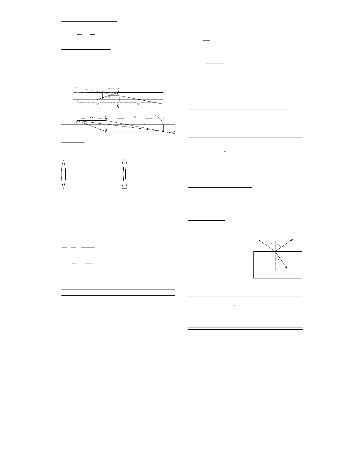
Polarizing Angle: by Brewster’s Law, the angle of
Spherical Refracting Surface This refers to two
incidence that produces complete polarization in the
materials with a single refracting surface.
reflected light from an amorphous material such as glass. p = object distance tan n non-polarized B 2 Source
i = image distance [m] (positive for real n n 1 b b 1 n2 n n 2 1 images) 90 rB n polarized p i r f = focal point [m] 1 n = index of refraction n n = index of refraction 2 Mh ni
r = radius [m] (positive when facing a 1 B = angle of incidence r h n p
convex surface, unlike with mirrors) producing a 90° angle 2 M = magnification between reflected and h' = image height [m] refracted rays. partially polarized h = object height [m] r = angle of incidence of the
Constructive and Destructive Interference by Single refracted ray.
and Double Slit Defraction and Circular Aperture
Intensity of light passing through a polarizing lense:
Young’s double-slit experiment (bright fringes/dark fringes): [Watts/m2]
d = distance between the slits [m] Double Slit initially unpolarized: I 1 I I = intensity [W/m2] = the angle between a normal 20 Constructive:
I0 = intensity of source [W/m2] line extending from midway initially polarized: Ldm sin = angle between the polarity 2 between the slits and a line I0I cos of the source and the lens. Destructive: extending from the midway sin ( ) Ldm 1 point to the point of ray 2
Tom Penick tomzap@eden.com www.teicontrols.com/notes 1/31/99
Tài liệu liên quan:
-

Tán xạ ánh sáng và Hiệu ứng Tyndall - Lý thuyết và Ứng dụng môn Vật lý đại cương 2 | Học viện Công Nghệ Bưu Chính Viễn Thông
9 5 -

Chương 23: Quang học lượng tử môn Vật lý đại cương 2 | Học viện Công Nghệ Bưu Chính Viễn Thông
4 2 -

Chương 24: Cơ Học Lượng Tử - Tính Sóng-Hạt và Phương Trình Schrödinger môn Vật lý đại cương 2 | Học viện Công Nghệ Bưu Chính Viễn Thông
7 4 -

Chủ đề 2: Mạch điện xoay chiều chỉ có 1 phần tử môn Vật lý đại cương 2 | Học viện Công Nghệ Bưu Chính Viễn Thông
5 3 -

Chủ đề 3: Mạch điện xoay chiều RLC mắc nối tiếp môn Vật lý đại cương 2 | Học viện Công Nghệ Bưu Chính Viễn Thông
4 2