Short-Circuit Current Calculations môn Vật lý đại cương 2 | Học viện Công Nghệ Bưu Chính Viễn Thông
At some distance from the terminals, depending upon wire size, theL-N fault current is lower than the L-L fault current . Tài liệu giúp bạn tham khảo, ôn tập và đạt kết quả cao. Mời đọc đón xem!
Môn: Vật lý đại cương 2 298 tài liệu
Trường: Học viện Công Nghệ Bưu Chính Viễn Thông 1.7 K tài liệu
Tác giả:


Preview text:
Short Circuit Current Calculations
Basic Point-to-Point Calculation Procedure
At some distance from the terminals, depending upon wire size, the L-N fault Step 1.
Determine the transformer full load amps (F.L.A.) from
current is lower than the L-L fault current. The 1.5 multiplier is an approximation
and will theoretically vary from 1.33 to 1.67. These figures are based on change in
turns ratio between primary and secondary, infinite source available, zero feet from
terminals of transformer, and 1.2 x %X and 1.5 x %R for L-N vs. L-L resistance a
reactance values. Begin L-N calculations at transformer secondary terminals, then proceed point-to-point. Step 5.
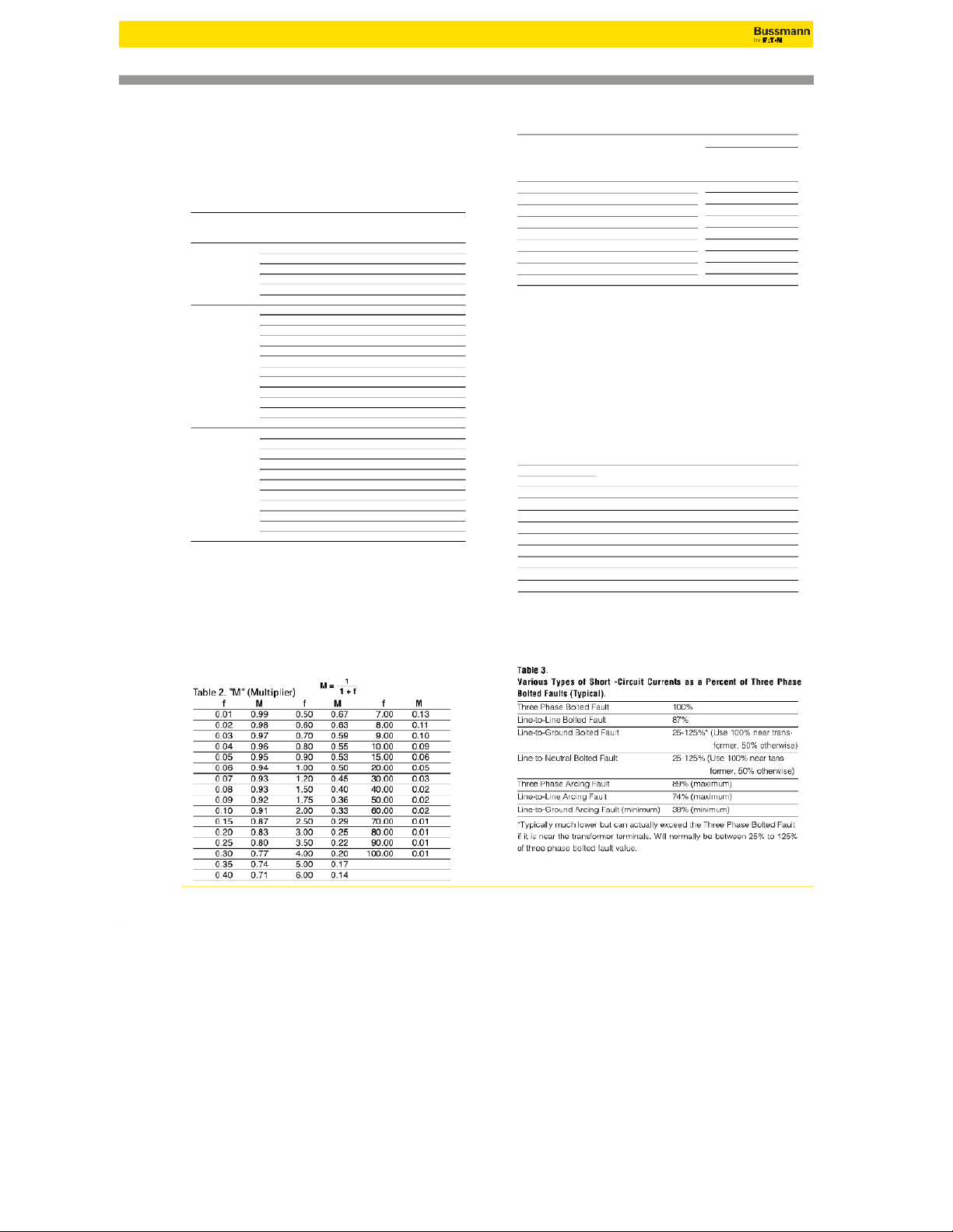
Calculate "M" (multiplier) or take from Table 2. M = 1
either the nameplate, the following formulas or Table 1: Multiplier = 100 1 +f *% Ztransformer Step 6.
Calculate the available short circuit symmetrical RMS
current at the point of fault. Add motor contribution, if Step 2.
Find the transformer multiplier. See Notes 1 and 2 applicable.
* Note 1. Get %Z from nameplate or Table 1. Transformer impedance (Z) helps to IS.C. sym. RMS = IS.C. xM
determine what the short circuit current will be at the transformer secondary.
Transformer impedance is determined as follows: The transformer secondary is short Step 6A. Motor short circuit contribution, if significant, may be
circuited. Voltage is increased on the primary until full load current flows in the
added at all fault locations throughout the system. A
secondary. This applied voltage divided by the rated primary voltage (times 100) is the
practical estimate of motor short circuit contribution is to impedance of the transformer.
multiply the total motor current in amps by 4. Values of 4 to 6 are commonly accepted.
Example: For a 480 Volt rated primary, if 9.6 volts causes secondary full load current to
flow through the shorted secondary, the transformer impedance is 9.6/480 = .02 = 2%Z.Calculation of Short-Circuit Currents When Primary
* Note 2. In addition, UL 1561 listed transformers 25kVA and larger have a ± 10%
Available Short-Circuit Current is Known
impedance tolerance. Short circuit amps can be affected by this tolerance. Therefore, for
high end worst case, multiply %Z by .9. For low end of worst case, multiply %Z by 1.1.
Use the following procedure to calculate the level of fault current at the secondary
Transformers constructed to ANSI standards have a ±7.5% impedance tolerance
of a second, downstream transformer in a system when the level of fault current a (two-winding construction).
the transformer primary is known. Step 3.
Determine by formula or Table 1 the transformer let- MAIN
through short-circuit current. See Notes 3 and 4. TRANSFORMER
IS.C. = TransformerF.L.A. x Multiplier
Note 3. Utility voltages may vary ±10% for power and ±5.8% for 120 Volt lighting
services. Therefore, for highest short circuit conditions, multiply values as calculated in IS.C. primary IS.C. secondary H.V. UTILITY
step 3 by 1.1 or 1.058 respectively. To find the lower end worst case, multiply results in CONNECTION
step 3 by .9 or .942 respectively.
Note 4. Motor short circuit contribution, if significant, may be added at all fault locations IS.C. primary IS.C. secondary
throughout the system. A practical estimate of motor short circuit contribution is to
multiply the total motor current in amps by 4. Values of 4 to 6 are commonly accepted.Step A. Calculate the "f" factor (IS.C. primary known) 3Ø Step 4. Faults Calculate the "f" factor. f = 1.732 xL xI3Ø 3(Ø I S.T Cr.a pn ri sf m o ar r y m a e n r d
f = IS.C. primary xVprimary x1.73 (%Z) C x n x EL-L 1Ø Line-to-Line (L-L) Faults 2 xL xI I L-L S.C. secondary are 100,000 xkVA transformer 3Ø fault values) See Note 5 & Table 3 f = C x n xEL-L 1Ø Transformer
1Ø Line-to-Neutral (L-N) Faults 2 xL xIL-N† (IS.C. primary and IS.C. primary xVprimary x (%Z) See Note 5 & Table 3 f = C x n xE 1Ø fault values: 100,000 xkVA L-N transformer IS.C. secondary are f = Where:
L = length (feet) of conductor to the fault. IS.C. secondaryis L-L)
C=constant from Table 4 of “C” values for conductors and
Table 5 of “C” values for busway. Step B. Calculate "M" M = (multiplier). 1
n=Number of conductors per phase (adjusts C value for parallel runs) 1 +f
I=Available short-circuit curent in amperes at beginning
Step C. Calculate the short-circuit current at the secondary of the of circuit.
transformer. (See Note under Step 3 of "Basic Point-to- E=Voltage of circuit.
IS.C. secondary =Vprimary xM xIS.C. primary Point Calculation Procedure".)
† Note 5. The L-N fault current is higher than the L-L fault current at the secondary
terminals of a single-phase center-tapped transformer. The short-circuit current available Vsecondary
(I) for this case in Step 4 should be adjusted at the transformer terminals as follows: At
L-N center tapped transformer terminals, IL-N = 1.5 x IL-L at Transformer Terminals. 237 ©2014 Eaton
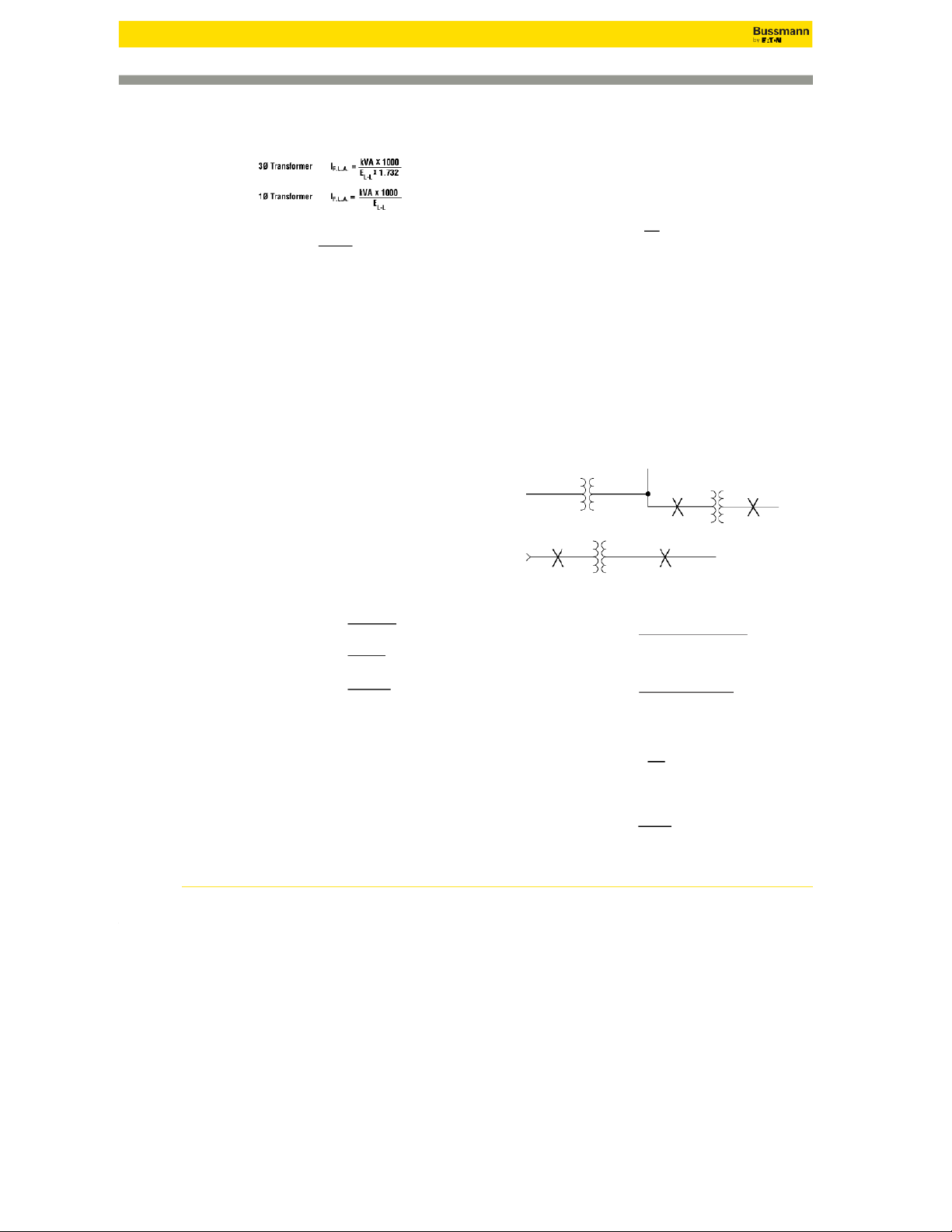
Short-Circuit Current Calculations Three-Phase Short Circuits System A Available Utility One-Line Diagram Fault X1 Fault X3 Infinite Assumption
Step 1. If.l. =1500 X1000 = 1804.3A
Step 4. f=1.732 X50 X55,137 = 0.4484 1500 KVA Transformer 480 X1.732 22,185 X1 X480 480V, 3Ø, 3.5%Z, 3.45% X, 0.56%R Step 2. Multipler 100 = 31.746 Step 5. M = = 0.6904 1 1 3.5 X0.9† 1 + 0.4483 If.l.=1804A
Step 3. Is.c. = 1804.3 X31.746 = 57,279A
Step 6. Is.c. sym RMS = 55,137 X0.6904 = 38,067A 25’ - 500kcml Cu
Is.c. motor contribution** = 4 X1804.3 = 7217A
Is.c. motor contribution** = 4 X1804.3 = 7217A 3 Single Conductors 6 Per Phase
Itotal s.c. sym RMS = 57,279 + 7217 = 64,496A
Itotal s.c. sym RMS (X3)= 38,067 + 7217 = 45,284A Magnetic Conduit Fault X2 2 2000A Switch
Step 4. f=1.732 X25 X57,279 = 0.0388 KRP-C 2000SP Fuse 22,185 X6 X480 Step 5. M = = 0.9626 1 1 + 0.0388 400A Switch LPS-RK-400SP Fuse
Step 6. Is.c. sym RMS = 57,279 X0.9626 = 55,137A I X 50’ - 500 kcmil Cu
s.c. motor contribution** = 4 1804.3 = 7217A 3 Single Conductors
Itotal s.c. sym RMS = 55,137 + 7217 = 62,354A Magnetic Conduit 3 Motor Contribution* M *See note 4 on page 240.
**Assumes 100% motor load. If 50% of this load was from motors. Is.c. motor contrib. = 4 X1804 X 0.5 = 3,608A †See note 2 on page 240 System B One-Line Diagram Fault X1 Fault X3 Available Utility Infinite Assumption
Step 1. Is.c. =1000 X1000 = 1202.8A
Step 4. f=1.732 X20 X36,761 = 0.1161 1000 KVA Transformer 480 X1.732 2 X 11,424 X 480 480V, 3Ø, 3.5%Z, Step 2. Multipler = 100 = 31.746 Step 5. M = = 0.8960 1 If.I.=1203A 3.5 X0.9† 1 + 0.1161 1 30’ - 500kcml Cu 3 Single Conductors
Step 3. Is.c. = 1202.8 X31.746 = 38,184A
Step 6. Is.c. sym RMS = 36,761 X0.8960 = 32,937A 4 Per Phase PVC Conduit 2 1600A Switch Fault X2 Fault X4 KRP-C 1500SP Fuse
Step 4. f=1.732 X30 X38,184 = 0.0387
Step A. f=32,937 X480 X1.732 X(1.2 X0.9) = 1.3144 26,706 X4 X480 100,000 X225 Step 5. M = = 0.9627 1 Step B. M = 1 = 0.4321 400A Switch LPS-RK-350SP Fuse 1 + 0.0387 1 + 1.3144
Step 6. Is.c. sym RMS = 38,184 X0.9627 = 36,761A
Step C. Is.c. sym RMS = 480 X0.4321 X32,937 = 32,842A 20’ - 2/0 Cu 208 3 Single Conductors 2 Per Phase PVC Conduit 3 225 KVA Transformer 208V, 3Ø 1.2%Z
This example assumes no motor contribution. 4 238 ©2014 Eaton
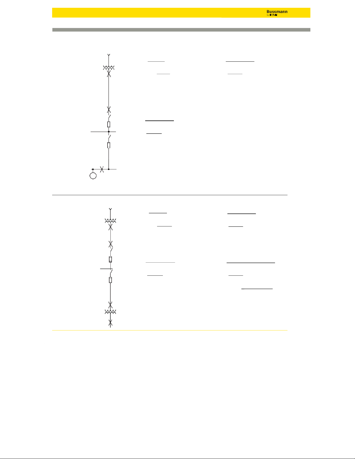
Short-Circuit Current Calculations Single-Phase Short Circuits
Short circuit calculations on a single-phase center tapped transformer system
require a slightly different procedure than 3Ø faults on 3Ø systems. A
1. It is necessary that the proper impedance be used to represent the primary system. B
For 3Ø fault calculations, a single primary conductor impedance is used from the C
source to the transformer connection. This is compensated for in the 3Ø short circuit Primary
formula by multiplying the single conductor or single-phase impedance by 1.73.
However, for single-phase faults, a primary conductor impedance is considered from Secondary
the source to the transformer and back to the source. This is compensated in the
calculations by multiplying the 3Ø primary source impedance by two.
2. The impedance of the center-tapped transformer must be adjusted for the Short
half-winding (generally line-to-neutral) fault condition. Circuit
The diagram at the right illustrates that during line-to-neutral faults, the full primary
winding is involved but, only the half-winding on the secondary is involved.
Therefore, the actual transformer reactance and resistance of the half-winding
condition is different than the actual transformer reactance and resistance of the full
winding condition. Thus, adjustment to the %X and %R must be made when
considering line-to-neutral faults. The adjustment multipliers generally used for this condition are as follows: Primary
• 1.5 times full winding %R on full winding basis.
• 1.2 times full winding %X on full winding basis. Secondary
Note: %R and %X multipliers given in “Impedance Data for Single Phase Short Circuit
Transformers” Table may be used, however, calculations must be adjusted to indicate transformer kVA/2.
3. The impedance of the cable and two-pole switches on the system must be L2NL 1
considered “both-ways” since the current flows to the fault and then returns to the
source. For instance, if a line-to-line fault occurs 50 feet from a transformer, then
100 feet of cable impedance must be included in the calculation.
The calculations on the following pages illustrate 1Ø fault calculations on a
single-phase transformer system. Both line-to-line and line-to-neutral faults are considered. L1 Note in these examples:
a. The multiplier of 2 for some electrical components to account for the single-phase fault current flow, N Short Circuit
b. The half-winding transformer %X and %R multipliers for the line-to-neutral fault situation, and L2 50 Feet ©2014 Eaton 239
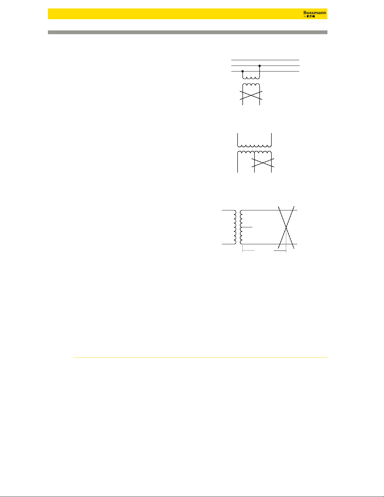
Short-Circuit Current Calculations Single-Phase Short Circuits System A One-Line Diagram Line-to-Line (L-L) Fault Line-to-Neutral (L-N) Fault Available Utility Infinite Assumption Fault X1Fault X1 Fault X1
Step 1. If.l. =75 X1000 = 312.5A
Step 1. If.l. =75 X1000 = 312.5A 240 240 75KVA, 1Ø Transformer. 1.22%X, 0.68%R Step 2. Multipler = 100 = 79.37 Step 2. Multipler = 100 = 79.37 1.40%Z 1.4 X0.9† 1.4 X0.9† 120/240V
Step 3. Is.c. (L-L) = 312.5 X79.37 = 24,802A
Step 3*. Is.c. (L-N) = 24,802 X1.5 = 37,202A 25’ - 500kcml Cu Magnetic Conduit 3 Single Conductors Fault X2 Fault X2
Step 4. f=2 X25 X24,802 = 0.2329 22,185 X1 X240
Step 4. f=2 X25 X37,202 = 0.6987 22,185 X1 X120 Step 5. M = = 0.81 1 11 2 1 + 0.2329 Step 5. M = = 0.5887 1 1 + 0.6987
Step 6. Is.c. (L-L) (X2)= 24,802 X0.8111 = 20,116 400A Switch
Step 6*. Is.c. (L-N) (X2)= 37,202 X0.5887 = 21,900A LPN-RK-400SP Fuse 50’ - 3 AWG Cu Magnetic Conduit Fault X3 Fault X3 3 Single Conductors
Step 4. f=2 X50 X20,116 = 1.7557
Step 4. f=2 X50 X21,900** = 3.8323 4774 X1 X240 4774 X1 X120 3 Step 5. M = = 0.3629 1 Step 5. M = 1 = 0.2073 1 + 1.7557 1 + 3.823
Step 6. Is.c. (L-L) (X3)= 20,116 X0.3629 = 7,300A
Step 6*. Is.c. (L-N) (X3)= 21,900 X0.2073 = 4,540A
† In addition, UL 1561 listed transformers 25kVA
* Note 5. The L-N fault current is higher than the L-L
and larger have a ± 10% impedance tolerance.
fault current at the secondary terminals of a single-
Short circuit amps can be affected by this
phase center-tapped transformer. The short-circuit
tolerance. Therefore, for high end worst case,
current available (I) for this case in Step 4 should be
multiply %Z by 0.9. For low end of worst case,
adjusted at the transformer terminals as follows: At L-N
multiply %Z by 1.1. Transformers constructed to
center tapped transformer terminals, IL-N = 1.5 x IL-L at
ANSI standards have a ±7.5% impedance Transformer Terminals.
tolerance (two-winding construction).
**Assumes the neutral conductor and the line conductor are the same size. 240 ©2014 Eaton
Short-Circuit Current Calculations Impedance & Reactance Data Transformers
Impedance Data for Single-Phase Transformers Suggested Normal Range Impedance Multipliers**
Table 1. Short-Circuit Currents Available from X/R Ratio of Percent For Line-to-Neutral kVA for Impedance (%Z)* Faults Various Size Transformers 1Ø Calculation for %X for %R
(Based upon actual field nameplate data or from utility transformer worst case 25.0 1.1 1.2–6.0 0.6 0.75 impedance) 37.5 1.4 1.2–6.5 0.6 0.75 50.0 1.6 1.2–6.4 0.6 0.75 Voltag e Ful % Short 75.0 1.8 1.2–6.6 0.6 0.75
and Load Impedance†† Circuit 100.0 2.0 1.3–5.7 0.6 0.75
Phase kVA Amps (Nameplate) Amps † 167.0 2.5 1.4–6.1 1.0 0.75 25 104 1.5 12175 37.5 156 1.5 18018 250.0 3.6 1.9–6.8 1.0 0.75 120/240 50 208 1.5 23706 333.0 4.7 2.4–6.0 1.0 0.75 1 ph.* 75 313 1.5 34639 500.0 5.5 2.2–5.4 1.0 0.75 100 417 1.6 42472
* National standards do not specify %Z for single-phase transformers. Consult 167 696 1.6 66644
manufacturer for values to use in calculation. 45 125 1.0 13879
**Based on rated current of the winding (one–half nameplate kVA divided by 3 .02 8 1 0 752
secondary line-to-neutral voltage). 112.5 312 1.11 31259 150 416 1.07 43237
Note: UL Listed transformers 25 kVA and greater have a ± 10% tolerance on 120/208 225 625 1.12 61960 3 ph.** 300 833 1.11 83357 their impedance nameplate. 500 1388 1.24 124364
This table has been reprinted from IEEE Std 242-1986 (R1991), IEEE 750 2082 3.50 66091
Recommended Practice for Protection and Coordination of Industrial and 1000 2776 3.50 88121 1500 4164 3.50 132181
Commercial Power Systems, Copyright©1986 by the Institute of Electrical an 2000 5552 4.00 154211
Electronics Engineers, Inc. with the permission of the IEEE Standards 2500 6940 4.00 192764 Department. 75 90 1.00 10035 112.5 135 1.00 15053
.Impedance Data for Single-Phase and Three-Phase Transformers- 150 181 1.20 16726 Supplement† 225 271 1.20 25088 kVA Suggested 300 361 1.20 33451 1Ø 3Ø %Z X/R Ratio for Calculation 277/480 500 602 1.30 51463 3 ph.** 750 903 3.50 28672 10 — 1.2 1.1 1000 1204 3.50 38230 15 — 1.3 1.1 1500 1806 3.50 57345 75 1.11 1.5 2000 2408 4.00 66902 150 1.07 1.5 2500 3011 4.00 83628 225 1.12 1.5 * Single-pha s ev alues are L-N val ues at transfo rmer terminals. These figures 300 1.11 1.5
are based on change in turns rat i o bet ween primary and seconda ry ,1 0 , 00
KVA primary, zero feet from terminals of transf ormer, 1.2 (%X) and 1.5 (%R) 333 — 1.9 4.7 multipliers for L-N vs. L-L reactanc e a n d resist an c e v alues and transf ormer 500 1.24 1.5 X/R ratio = 3. 500 — 2.1 5.5
**Three-phase short-circuit currents based on “infinite” primary.
†These represent actual transformer nameplate ratings taken from field
†† UL list ed transformers 25 KVA or greater have a ±10% impedance toler - installations.
ance. Short-circuit amps sho wn in Table 1 reflect –10% condition. Trans-
formers construct ed t o ANSI st andards have a ±7.5% impedance tolerance (two-winding co n st ruction).
Note: UL Listed transformers 25kVA and greater have a ±10% tolerance on
† Fluctuations in system voltage wil affect the available short-circuit current. their impedance nameplate.
For example, a 10% increase in system voltage will result in a 10% greater
available short-circuit currents than as shown i n Tabl e 1. ©2014 Eaton 241
Short-Circuit Current Calculations
Conductors & Busways "C" Values
Table 4. “C ” Values for Conductors Copper AWG Three Single Conductors Three-Conductor Cable or Conduit Conduit kcmil Steel Nonmagnetic Steel Nonmagnetic 600V 5kV 15kV 600V 5kV 15kV 600V 5kV 15kV 600V 5kV 15kV 14 389 -- 389 - - 389 --389 -- 12 617 -- 617 - - 617 --617 -- 10 981 -- 982 - - 982 --982 -- 8 1557 1551 - 1559 1555 - 1559 1557 - 1560 1558 - 6 2425 2406 2389 2430 2418 2407 2431 2425 2415 2433 2428 2421 4 3806 3751 3696 3826 3789 3753 3830 3812 3779 3838 3823 3798 3 4774 4674 4577 4811 4745 4679 4820 4785 4726 4833 4803 4762 2 5907 5736 5574 6044 5926 5809 5989 5930 5828 6087 6023 5958 1 7293 7029 6759 7493 7307 7109 7454 7365 7189 7579 7507 7364 1/0 8925 8544 7973 9317 9034 8590 9210 9086 8708 9473 9373 9053 2/0 10755 10062 9390 11424 10878 10319 11245 11045 10500 11703 11529 11053 3/0 12844 11804 11022 13923 13048 12360 13656 13333 12613 14410 14119 13462 4/0 15082 13606 12543 16673 15351 14347 16392 15890 14813 17483 17020 16013 250 16483 14925 13644 18594 17121 15866 18311 17851 16466 19779 19352 18001 300 18177 16293 14769 20868 18975 17409 20617 20052 18319 22525 21938 20163 350 19704 17385 15678 22737 20526 18672 22646 21914 19821 24904 24126 21982 400 20566 18235 16366 24297 21786 19731 24253 23372 21042 26916 26044 23518 500 22185 19172 17492 26706 23277 21330 26980 25449 23126 30096 28712 25916 600 22965 20567 17962 28033 25204 22097 28752 27975 24897 32154 31258 27766 750 24137 21387 18889 29735 26453 23408 31051 30024 26933 34605 33315 29735 1,000 25278 22539 19923 31491 28083 24887 33864 32689 29320 37197 35749 31959 Aluminum 14 237 - - 237 -- 237 --237 -- 12 376 - - 376 -- 376 --376 -- 10 599 - - 599 -- 599 --599 -- 8 951 950 - 952 951 - 952 951 - 952 952 - 6 1481 1476 1472 1482 1479 1476 1482 1480 1478 1482 1481 1479 4 2346 2333 2319 2350 2342 2333 2351 2347 2339 2353 2350 2344 3 2952 2928 2904 2961 2945 2929 2963 2955 2941 2966 2959 2949 2 3713 3670 3626 3730 3702 3673 3734 3719 3693 3740 3725 3709 1 4645 4575 4498 4678 4632 4580 4686 4664 4618 4699 4682 4646 1/0 5777 5670 5493 5838 5766 5646 5852 5820 5717 5876 5852 5771 2/0 7187 6968 6733 7301 7153 6986 7327 7271 7109 7373 7329 7202 3/0 8826 8467 8163 9110 8851 8627 9077 8981 8751 9243 9164 8977 4/0 10741 10167 9700 11174 10749 10387 11185 11022 10642 11409 11277 10969 250 12122 11460 10849 12862 12343 11847 12797 12636 12115 13236 13106 12661 300 13910 13009 12193 14923 14183 13492 14917 14698 13973 15495 15300 14659 350 15484 14280 13288 16813 15858 14955 16795 16490 15541 17635 17352 16501 400 16671 15355 14188 18506 17321 16234 18462 18064 16921 19588 19244 18154 500 18756 16828 15657 21391 19503 18315 21395 20607 19314 23018 22381 20978 600 20093 18428 16484 23451 21718 19635 23633 23196 21349 25708 25244 23295 750 21766 19685 17686 25976 23702 21437 26432 25790 23750 29036 28262 25976 1,000 23478 21235 19006 28779 26109 23482 29865 29049 26608 32938 31920 29135
Note: These values are equal to one over the impedance per foot and based upon resistance and reactance values found in IEEE Std 241-1990 (Gray Book), IEEE Recommended Practice for Electric Power
Systems in Commerical Buildings & IEEE Std 242-1986 (Buff Book), IEEE Recommended Practice for Protection and Coordination of Industrial and Commercial Power Systems. Where - resistance and reac
tance values differ or are not available, the Buff Book values have been used. The values for reactance in determining the C Value at 5 KV & 15 KV are from the Gray Book only (Values for 14-10 AWG at 5 kV
and 14-8 AWG at 15 kV are not available and values for 3 AWG have been approximated).
Table 5. “C ” Values for Busway Ampacity Busway Plug-In Feeder High Impedance Copper Aluminum Cop per Aluminum Copper 225 28700 23000 18700 12000 — 400 38900 34700 23900 21300 — 600 41000 38300 36500 31300 — 800 46100 57500 49300 44100 — 1000 69400 89300 62900 56200 15600 1200 94300 97100 76900 69900 16100 1350 119000 104200 90100 84000 17500 1600 129900 120500 101000 90900 19200 2000 142900 135100 134200 125000 20400 2500 143800 156300 180500 166700 21700 3000 144900 175400 204100 188700 23800 4 — 27 000 78 — 256400 —
Note: These values are equal t o one over the impedance per foot for
impedance in a survey of industry. 242 ©2014 Eaton Voltage Drop Calculations
Ratings of Conductors and Tables to Determine Volt Loss
With larger loads on new installations, it is extremely important to consider volt
Select number from Table A, three-phase at 80% power factor, that is nearest
loss, otherwise some very unsatisfactory problems are likely to be
but not greater than 764. This number is 745 which indicates the size of wire encountered. needed: 6 AWG.
The actual conductor used must also meet the other sizing requirements such aLine-to-Neutral
full-load current, ambient temperature, number in a raceway, etc.
For line to neutral voltage drop on a 3 phase system, divide the three phase
value by 1.73. For line to neutral voltage drop on a single phase system, How to Figure Volt Loss
divide single phase value by 2.
Multiply distance (length in feet of one wire) by the current (expressed in amps) by the
figure shown in table for the kind of current and the size of wire to be used, by one over Open Wiring
the number of conductors per phase.
The volt loss for open wiring installations depends on the separation between
Then, put a decimal point in front of the last 6 digits–you have the volt loss to be
conductors. The volt loss is approximately equal to that for conductors in non-magnetic conduit.
Example – 6 AWG copper wire, one per phase, in 180 feet of steel
conduit–3 phase, 40 amp load at 80% power factor.
Installation in Conduit, Cable or Raceway
NEC®Tables 310.15(B)(16) through 310.15(B)(19) give allowable ampacitie
Multiply feet by amperes: 180 x 40 = 7200
(current-carrying capacities) for not more than three current carrying
Multiply this number by number from table for 6 AWG wire three-
conductors in a conduit, cable, or raceway. Where the number of current
phase at 80% power factor: 7200 x 745 = 5364000 † Multiply by 1 5364000 = 1
carrying conductors exceeds three the allowable ampacity of each conductor x x 5364000 = 5364000 #/phase 1
must be reduced as shown in the following tables: Place decimal point pl 6 aces to left:
This gives volt loss to be expected: 5.364V
Installation in Conduit, Cable or Raceway per 310.15(B)(2)(a) The Number of Percentage of Values Conductors In One In Tables 310.16 And
(For a 240V circuit the % voltage drop is 5.364 x 100 or 2.23%). Conduit, Raceway 310.18 240 Or Cable
Table A and B take into consideration reactance on AC circuits as 4 to 6 80%
well as resistance of the wire. 7 to 9 70%
Remember on short runs to check to see that the size and type 10 to 20 50%
of wire indicated has sufficient ampacity. 21 to 30 45% 31 to 40 40% 41 and over 35% expected on that circuit.
Conditions Causing Higher Volt Loss How to Select Size of Wire
The voltage loss is increased when a conductor is operated at a higher
Multiply distance (length in feet of one wire) by the current (expressed in
temperature because the resistance increases.
amps), by one over the number of conductors per phase.
Room Temperature Affects Ratings
Divide that figure into the permissible volt loss multiplied by 1,000,000.
The ampacities (carrying capacities) of conductors are based on a room
temperature of either 30°C or 40ºC. For derating based upon 30ºC ambient, i
Example – Copper in 180 feet of steel conduit–3 phase, 40 amp
room temperature is higher, the ampacities are reduced by using the followin
Ioad at 80% power factor–maximum volt loss permitted from local
multipliers; (for 0-2000 volt, insulated conductors not more than 3 conducto code equals 5.5 volts.
in raceway or direct buried, Table 310.15(B)(2)(a)). For room temperatures
Multiply feet by amperes by 1180 x 40 x 1= 7200.
based upon a 40ºC ambient, see Table 310.15(B)(2)(b). #/phase 1
Divide permissible volt loss multiplied by 1,000,000 by this number: 5.5 x 1,000,000 = 764.
Room Temperature Affects Ratings Room Ampacity Multiplier 7200 Temperature TW THW, THWN THHN, XHHW*
Look under the column in Table A and B applying to the type of current and °C°F (60° C Wire) (75° C Wire) (90° C Wire) 31-35 87-95 .91 .94 .96
power factor for the value nearest, but not above your result – you have the 36-40 96-104 .82 .88 .91 size of wire needed. 41-45 105-113 .71 .82 .87 46-50 114-122 .58 .75 .82 51-55 123-131 .41 .67 .76 56-60 132-140 – .58 .71 61-70 141-158 – .33 .58 71-80 159-176 – – .41 † Value from Table A ©2014 Eaton 243 Voltage Drop Calculations
Table A — Copper Conductors — Ratings & Volt Loss† Conduit Wire Ampacity Direct
Volt Loss (See explanation prior page.) Size Type Type Type Current Three-Phase Single-Phase T, TW RH, RHH,
(60 Cycle, Lagging Power Factor.)
(60 Cycle, Lagging Power Factor.) (60°CTHWN, THHN, 100% 90% 80% 70% 60% 100% 90% 80% 70% 60% Wire) RHW, XHHW THW (90°C ) e r i(75°CW Wire) Steel 14 20* 20* 25* 6140 5369 4887 4371 3848 3322 6200 5643 5047 4444 3836 Conduit 12 25* 25* 30* 3860 3464 3169 2841 2508 2172 4000 3659 3281 2897 2508 10 30 35* 40* 2420 2078 1918 1728 1532 1334 2400 2214 1995 1769 1540 8 40 50 55 1528 1350 1264 1148 1026 900 1560 1460 1326 1184 1040 6 55 65 75 982 848 812 745 673 597 980 937 860 777 690 470 85 95 616 536 528 491 450 405 620 610 568 519 468 385 100 110 490 433 434 407 376 341 500 501 470 434 394 295 115 130 388 346 354 336 312 286 400 409 388 361 331 1 110 130 150 308 277 292 280 264 245 320 337 324 305 283 0 125 150 170 244 207 228 223 213 200 240 263 258 246 232 00 145 175 195 193 173 196 194 188 178 200 227 224 217 206 000 165 200 225 153 136 162 163 160 154 158 187 188 184 178 0000 195 230 260 122 109 136 140 139 136 126 157 162 161 157 250 215 255 290 103 93 123 128 129 128 108 142 148 149 148 300 240 285 320 8115 8 06 77 117 117 90 125 133 135 135 350 260 310 350 7 8316 07 69 109 109 78 113 122 126 126 400 280 335 380 6 1496 909 103 104 70 105 114 118 120 500 320 380 430 52 50 81 90 94 96 58 94 104 109 111 600 335 420 475 43 43 75 84 89 92 50 86 97 103 106 750 400 475 535 34 36 68 78 84 88 42 79 91 97 102 1000 455 545 615 26 31 62 72 78 82 36 72 84 90 95 Non- 14 20* 20* 25* 6140 5369 4876 4355 3830 3301 6200 5630 5029 4422 3812 Magnetic 12 25* 25* 30* 3464 3464 3158 2827 2491 2153 4000 3647 3264 2877 2486 Conduit 10 30 35* 40* 2420 2078 1908 1714 1516 1316 2400 2203 1980 1751 1520 0 ( 5 L 0 ead 84 55 1528 1350 1255 1134 1010 882 1560 1449 1310 1166 1019 Co 5 v 6 e 5 red 65 75 982 848 802 731 657 579 980 926 845 758 669 Cabl 0 e 8 s 5 or 47 95 616 536 519 479 435 388 620 599 553 502 448 Instal 5 l 1 a 0ti 0 on 38 110 470 433 425 395 361 324 500 490 456 417 375 in Fib 5 r 1e 1 o 5 r 29 130 388 329 330 310 286 259 380 381 358 330 300 0 130 Other 1 15 1 0 1 308 259 268 255 238 219 300 310 295 275 253 5 150 2 Non 1 - 7 0 0 1 244 207 220 212 199 185 240 254 244 230 214 Magnetic 00 145 175 195 193 173 188 183 174 163 200 217 211 201 188 Conduit, 000 165 200 225 153 133 151 150 145 138 154 175 173 167 159 Etc.) 0000 195 230 260 122 107 127 128 125 121 124 147 148 145 140 250 215 255 290 103 90 112 114 113 110 104 129 132 131 128 300 240 285 320 86 76 99 103 104 102 88 114 119 120 118 350 260 310 350 73 65 89 94 95 94 76 103 108 110 109 400 280 335 380 64 57 81 87 89 89 66 94 100 103 103 500 320 380 430 52 46 71 77 80 82 54 82 90 93 94 600 335 420 475 43 39 65 72 76 77 46 75 83 87 90 750 400 475 535 34 32 58 65 70 72 38 67 76 80 83 1000 455 545 615 26 25 51 59 63 66 30 59 68 73 77
*The overcurrent protection for conductor types marked with an (*) shall not exceed 15 amperes for 14 AWG, 20 amperes for 12 AWG, and 30 amperes for 10 AWG copper; or 15
amperes for 12 AWG and 25 amperes for 10 AWG aluminum and copper-clad aluminum after any correction factors for ambient temperature and number of conductors have been applied.
† Figures are L-L for both single-phase and three-phase. Three-phase figures are average for the three-phase. 244 ©2014 Eaton Voltage Drop Calculations
Table B — Aluminum Conductors — Ratings & Volt Loss† Conduit Wire Ampacity Direct
Volt Loss (See explanation two pages prior.) Size Type Type Type Current Three-Phase Single-Phase T, TW RH, RHH,
(60 Cycle, Lagging Power Factor.)
(60 Cycle, Lagging Power Factor.) (60°CTHWN, THHN, 100% 90% 80% 70% 60% 100% 90% 80% 70% 60% Wire) RHW, XHHW THW (90°C (75°C Wire) Wire) Steel 12 20* 20* 25* 6360 5542 5039 4504 3963 3419 6400 5819 5201 4577 3948 Conduit 10 25 30* 35* 4000 3464 3165 2836 2502 2165 4000 3654 3275 2889 2500 8 30 40 45 2520 2251 2075 1868 1656 1441 2600 2396 2158 1912 1663 6 40 50 60 1616 1402 1310 1188 1061 930 1620 1513 1372 1225 1074 4 55 65 75 1016 883 840 769 692 613 1020 970 888 799 708 3 65 75 85 796 692 668 615 557 497 800 771 710 644 574 2 75 90 100 638 554 541 502 458 411 640 625 580 529 475 1 85 100 115 506 433 432 405 373 338 500 499 468 431 391 0 100 120 135 402 346 353 334 310 284 400 407 386 358 328 00 115 135 150 318 277 290 277 260 241 320 335 320 301 278 000 130 155 175 259 225 241 234 221 207 260 279 270 256 239 0000 150 180 205 200 173 194 191 184 174 200 224 221 212 201 250 170 205 230 169 148 173 173 168 161 172 200 200 194 186 300 190 230 255 141 124 150 152 150 145 144 174 176 173 168 350 210 250 280 121 109 135 139 138 134 126 156 160 159 155 400 225 270 305 106 95 122 127 127 125 110 141 146 146 144 500 260 310 350 85 77 106 112 113 113 90 122 129 131 130 600 285 340 385 71 65 95 102 105 106 76 110 118 121 122 750 320 385 435 56 53 84 92 96 98 62 97 107 111 114 1000 375 445 500 42 43 73 82 87 89 50 85 95 100 103 Non- 12 20* 20* 25* 6360 5542 5029 4490 3946 3400 6400 5807 5184 4557 3926 Magnetic 10 25 30* 35* 4000 3464 3155 2823 2486 2147 4000 3643 3260 2871 2480 Conduit 8 30 40 45 2520 2251 2065 1855 1640 1423 2600 2385 2142 1894 1643 (Lead 6 40 50 60 1616 1402 1301 1175 1045 912 1620 1502 1357 1206 1053 Covered 4 55 65 75 1016 883 831 756 677 596 1020 959 873 782 668 Cables or 3 65 75 85 796 692 659 603 543 480 800 760 696 627 555 Installation 2 75 90 100 638 554 532 490 443 394 640 615 566 512 456 in Fibre or 1 85 100 115 506 433 424 394 360 323 500 490 455 415 373 Other 0 100 120 135 402 346 344 322 296 268 400 398 372 342 310 Non- 00 115 135 150 318 277 281 266 247 225 320 325 307 285 260 Magnetic 000 130 155 175 252 225 234 223 209 193 260 270 258 241 223 Conduit, 0000 150 180 205 200 173 186 181 171 160 200 215 209 198 185 Etc.) 250 170 205 230 169 147 163 160 153 145 170 188 185 177 167 300 190 230 255 141 122 141 140 136 130 142 163 162 157 150 350 210 250 280 121 105 125 125 123 118 122 144 145 142 137 400 225 270 305 106 93 114 116 114 111 108 132 134 132 128 500 260 310 350 85 74 96 100 100 98 86 111 115 115 114 600 285 340 385 71 62 85 90 91 91 72 98 104 106 105 750 320 385 435 56 50 73 79 82 82 58 85 92 94 95 1000 375 445 500 42 39 63 70 73 75 46 73 81 85 86
*The overcurrent protection for conductor types marked with an (*) shall not exceed 15 amperes for 14 AWG, 20 amperes for 12 AWG, and 30 amperes for 10 AWG copper; or 15
amperes for 12 AWG and 25 amperes for 10 AWG aluminum and copper-clad aluminum after any correction factors for ambient temperature and number of conductors have been applied.
† Figures are L-L for both single-phase and three-phase. Three-phase figures are average for the three-phase. ©2014 Eaton 245 Glossary Common Electrical Terminology Ohm Semiconductor Fuses
The unit of measure for electric resistance. An ohm is the amount of resistance that willFuses used to protect solid-state devices. See “High Speed Fuses.”
allow one amp to flow under a pressure of one volt. Short-Circuit Ohm’s Law
Can be classified as an overcurrent which exceeds the normal full load current of a
The relationship between voltage, current, and resistance, expressed by the equation E circuit by a factor many times (tens, hundreds or thousands greater). Also characteristic
= IR, where E is the voltage in volts, I is the current in amps, and R is the resistance inof this type of overcurrent is that it leaves the normal current carrying path of the circu ohms.
– it takes a “short cut” around the load and back to the source. One Time Fuses Short-Circuit Current Rating
Generic term used to describe a Class H nonrenewable cartridge fuse, with a single
The maximum short-circuit current an electrical component can sustain without the element.
occurrence of excessive damage when protected with an overcurrent protective device Overcurrent Single-Phasing
A condition which exists on an electrical circuit when the normal load current is
That condition which occurs when one phase of a three-phase system opens, either in a
exceeded. Overcurrents take on two separate characteristics – overloads and short-
low voltage (secondary) or high voltage (primary) distribution system. Primary or circuits.
secondary single-phasing can be caused by any number of events. This condition
results in unbalanced currents in polyphase motors and unless protective measures are Overload
taken, causes overheating and failure.
Can be classified as an overcurrent which exceeds the normal full load current of a
circuit. Also characteristic of this type of overcurrent is that it does not leave the normalThreshold Current
current carrying path of the circuit – that is, it flows from the source, through the
The symmetrical RMS available current at the threshold of the current-limiting range,
conductors, through the load, back through the conductors, to the source again.
where the fuse becomes current-limiting when tested to the industry standard. This Peak Let-Through Current, lp
value can be read off of a peak let-through chart where the fuse curve intersects the
A - B line. A threshold ratio is the relationship of the threshold current to the fuse’s
The instantaneous value of peak current let-through by a current-limiting fuse, when itcontinuous current rating.
operates in its current-limiting range. Time-Delay Fuse
Renewable Fuse (600V & below)
A fuse with a built-in delay that allows temporary and harmless inrush currents to pass
A fuse in which the element, typically a zinc link, may be replaced after the fuse has without opening, but is so designed to open on sustained overloads and short-circuits.
opened, and then reused. Renewable fuses are made to Class H standards. Voltage Rating Resistive Load
The maximum open circuit voltage in which a fuse can be used, yet safely interrupt an
An electrical load which is characteristic of not having any significant inrush current. overcurrent. Exceeding the voltage rating of a fuse impairs its ability to clear an overlo
When a resistive load is energized, the current rises instantly to its steady-state value, or short-circuit safely.
without first rising to a higher value. Withstand Rating RMS Current
The maximum current that an unprotected electrical component can sustain for a
The RMS (root-mean-square) value of any periodic current is equal to the value of thespecified period of time without the occurrence of extensive damage.
direct current which, flowing through a resistance, produces the same heating effect in
the resistance as the periodic current does. Electrical Formulas To Find Single-Phase Two-Phase Three-Phase Direct Current Amperes when kVA is known kVA ≈ 1000 kVA ≈ 1000 kVA ≈ 1000 Not Applicable E E ≈ 2 E ≈ 1.73
Amperes when horsepower is known HP ≈ 746 HP ≈ 746 HP ≈ 746 HP ≈ 746 E ≈ % eff. ≈ pf E ≈ 2 ≈ % eff. ≈ pf E ≈ 1.73 ≈ % eff. ≈ pf E ≈ % eff.
Amperes when kilowatts are known kW ≈ 1000 kW ≈ 1000 kW ≈ 1000 kW ≈ 1000 E ≈ pf E ≈ 2 pf E ≈ 1.73 ≈ pf E Kilowatts I ≈ E ≈ pf I ≈ E ≈ 2 ≈ pf I ≈ E ≈ 1.73 ≈ pf I ≈ E 1000 1000 1000 1000 Kilovolt-Amperes I ≈ E I ≈ E ≈ 2 I ≈ E ≈ 1.73 Not Applicable 1000 1000 1000 Horsepower I ≈ E % eff. ≈ pf I ≈ E ≈ 2 ≈ % eff. ≈ pf I ≈ E ≈ 1.73 ≈ % eff. ≈ pf I ≈ E ≈ % eff. 746 746 746 746 Watts E ≈ I ≈ pf I ≈ E ≈ 2 ≈ pf I ≈ E ≈ 1.73 ≈ pf E ≈ I
Energy Efficiency = Load Horsepower ≈ 746 Load Input kVA ≈ 1000
Power Factor = pf = Power Consumed =W or kW = cosθ Apparent Power VA kVA I = Amperes E = Volts kW = Kilowatts kVA = Kilovolt-Amperes HP = Horsepower % eff. = Percent Efficiency pf = Power Factor ©2014 Eaton 263
Tài liệu liên quan:
-
Bài tập Vật lý nguyên tử môn Vật lý đại cương 2 | Học viện Công Nghệ Bưu Chính Viễn Thông
11 6 -
Bài tập Vật lý nguyên tử môn Vật lý đại cương 2 | Học viện Công Nghệ Bưu Chính Viễn Thông
11 6 -

Tán xạ ánh sáng và Hiệu ứng Tyndall - Lý thuyết và Ứng dụng môn Vật lý đại cương 2 | Học viện Công Nghệ Bưu Chính Viễn Thông
19 10 -

Chương 23: Quang học lượng tử môn Vật lý đại cương 2 | Học viện Công Nghệ Bưu Chính Viễn Thông
17 9 -

Chương 24: Cơ Học Lượng Tử - Tính Sóng-Hạt và Phương Trình Schrödinger môn Vật lý đại cương 2 | Học viện Công Nghệ Bưu Chính Viễn Thông
18 9