Study of infill print design on production cost-time of 3D printed ABS parts | Tài liệu môn công nghệ in trường Đại học sư phạm kỹ thuật TP Hồ Chí Minh
Abstract: The ever-growing adoption of Additive Manufacturing (AM) can be attributed to lowering prices of entry-level extrusion-based 3D printers. It has enabled use of AM for prototypes and, often, to produce complex custom commercial products. With increasing access to material extrusion-based 3D printers and newer materials, the influence of print parameters, Tài liệu giúp bạn tham khảo, ôn tập và đạt kết quả cao. Mời bạn đọc đón xem!
Môn: Công nghệ in 13 tài liệu
Trường: Trường Đại học Sư phạm Kỹ thuật Thành phố Hồ Chí Minh 4.4 K tài liệu
Tác giả:


Preview text:
308
Int. J. Rapid Manufacturing, Vol. 5, Nos. 3/4, 2015
Study of infill print design on production cost-time of 3D printed ABS parts
Liseli Baich, Guha Manogharan* and Hazel Marie
Department of Mechanical and Industrial Engineering, Youngstown State University, Youngstown, OH 44555, USA
Email: ljbaich@student.ysu.edu Email: gpmanogharan@ysu.edu Email: hmarie@ysu.edu *Corresponding author
Abstract: The ever-growing adoption of Additive Manufacturing (AM) can be
attributed to lowering prices of entry-level extrusion-based 3D printers. It has
enabled use of AM for prototypes and, often, to produce complex custom
commercial products. With increasing access to material extrusion-based 3D
printers and newer materials, the influence of print parameters, specifically
infill patterns on the mechanical strength and print costs, needs to be
investigated. This study presents the relationship between various infill designs
and different mechanical properties based on ASTM testing standards along
with production cost-time. Relevant infill designs are recommended based on
loading conditions and savings in production cost when compared to solid infill
design. The influence of production cost based on production grade and entry-
level printers on selection of infill design is presented. Findings from this study
will help formulate criteria for selection of optimal infill design based on
loading conditions and cost of printing.
Keywords: additive manufacturing; material extrusion; fused deposition
modelling; mechanical strength; infill design pattern; cost analysis.
Reference to this paper should be made as follows: Baich, L., Manogharan, G.
and Marie, H. (2015) ‘Study of infill print design on production cost-time of 3D printed AB
S parts’, Int. J. Rapid Manufacturing, Vol. 5, Nos. 3/4, pp.308–319.
Biographical notes: Liseli Baich is a Graduate Student pursuing a Master’s
degree in Industrial and Systems Engineering at Youngstown State University.
She joined the program in August 2014 and is currently a Cushwa Commercial
Shearing Fellowship recipient. She is conducting research in the field of 3D
printing. She previously finished her Bachelor’s in Civil and Construction
Engineering Technology with a minor in Business at Youngstown State in May
of 2014. She was a former swimmer on the YSU Swimming and Diving Team.
She is also Vice-President of Phi Sigma Rho, Sorority of Women Engineers.
Guha Manogharan is an Assistant Professor in the Department of Mechanical
and Industrial Engineering, College of STEM at Youngstown State University.
His research interests are in additive and hybrid manufacturing including
material development, process modelling and interdisciplinary mechanical and
aerospace applications. He received his PhD and MS in Industrial and Systems
Engineering from North Carolina State University. He graduated with a BS in
Mechanical Engineering from SASTRA University, India, in 2007.
Copyright © 2015 Inderscience Enterprises Ltd.
Study of infill print design on production cost-time of 3d printed ABS parts 309
Hazel Marie, PhD, PE, is Distinguished Professor and Chair of Mechanical and
Industrial Engineering at Youngstown State University. Her research interests
include FEA modelling with CFD flow analysis and have been applied to
solid–fluid interaction of thin film lubrication. A secondary research interest of
hers includes material characterisation of biomaterials. Prior to entering
academia, she worked as materials and process automation engineer and is a
licensed Professional Engineer in the State of Ohio.
This paper is a revised and expanded version of a paper entitled ‘Study of infill
print parameters on mechanical strength and production cost-time of 3D
printed ABS parts’ presented at the ‘26th International Solid Freeform
Fabrication Symposium’, Austin, TX, USA, 10–12 August 2015. 1 Introduction
Additive Manufacturing (AM) uses a Computer-Aided Design (CAD) model of the
desired part to selectively join materials layer by layer. This ‘Solid Freeform’ approach
to fabricate parts provides unique advantages such as lack of fixtures/jigs, part-design-
independent set-up and ability to produce multiple designs within a single build, among
others (Guo and Leu, 2013). It also provides the ability to custom-produce parts with
different part designs and materials, and provides an ever-growing possibility for
practical applications. According to ASTM F2792, AM processes can be categorised into
seven categories: vat photo-polymerisation, material jetting, binder jetting, material
extrusion, powder bed fusion, sheet lamination and directed energy deposition (ASTM
F2792, 2012). Among the different AM categories defined by ASTM, material extrusion
has in particular gained tremendous popularity for a variety of applications ranging from
DIY projects, STEM education and prototype fabrication to actual part production
(ASTM F2792, 2012; Bak, 2003; Conner et al 2014; Petrick and Simpson, 2013).
Material extrusion is an “AM process in which material is selectively dispensed through
a nozzle or orifice” (ASTM F2792, 2012). Since AM is relatively more affordable from
its earlier days (Jauhar et al., 2012), STEM programs and small and medium-sized
enterprises (SME) throughout the nation are adopting additive manufacturing in their
curriculums at a much lower cost (Conner et al, 2014). This method is also known as
Fused Deposition Modelling (FDM) and compared to other AM processes is relatively
cheaper and easier to set up with lower consumable and maintenance cost
(Solid Concepts, 2015). The focus of this study is to develop a framework related to
material extrusion AM, specifically ‘infill pattern’ which is an integral and often an
overlooked aspect with respect to resulting cost-production time requirements and
mechanical properties. Relevant background for this motivation and methodology are
presented in this work. Analyse s o f th e experimental result s from tensile ,compressio n and
bending tests are compared to material consumption and print costs for different
cost factors. Trend analysis based on print time, print cost, material volume and
feedstock cost is conducted to study the impact of highly varied costs of entry-level and production-grade printers. 310
L. Baich, G. Manogharan and H. Marie 2 Background
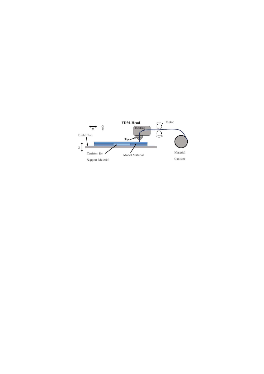
In the case of material extrusion as shown in Figure 1, there are several process
parameters that influence the final part strength, quality, cost and production time
including (but not limited to) (1) material and support selection (Fischer, 2015); (2) part
design (Kumar and Regalla, 2014); (3) layer thickness (Sood et al, 2010; Boschetto and
Bottini, 2014); (4) print design – wall thickness, infill pattern (Sood et al, 2010; Iyibilgin
et al., 2014); and (5) print conditions uniformity of extruder and/or build-bed temperature (Kumar and Regalla, 2014).
Figure 1 Material extrusion process
Source: Bagsik and Schöppner (2011)
With ever-increasing interests in AM and growth of open-access CAD and STL
repositories such as Thingiverse and PinShape to name a few, it is important to identify
relevant infill patterns and densities for desired strength and loading conditions for
different applications. This is of great significance because similar to other AM processes
(including material extrusion) the CAD model, as an STL file being water-tight knit 3D
surface facets, does not contain any information on the infill pattern. Most often, the
infill pattern is based on the ‘default’ settings of the 3D printer and/or open-source tool-
path-generating software. The CAD model also does not consider different loading
conditions during part life cycle and/or material properties of the print material.
Selection of infill dimensions and layer thickness independent of loading conditions
can significantly impact the mechanical properties, material cost and production (Sood
et al, 2010). Several open-access software packages are available including Slic3r,
Repetier and Simplify3D, to name a few, for most entry-level 3D printers to generate
tool-paths with varying levels of customisability. On the other hand, production-grade
printers such as Stratasys Fortus 3D printer use printer-specific closed access applications
such as Insight®, which is relatively less customisable. Although customisation is limited,
the accuracy of the production-grade printer is superior to that of entry-level 3D printers
(Pei et al., 2011). There are several controlled parameters in material extrusion such as
material including reinforcing fibres, uniformity in print conditions (e.g. temperature,
feed rate), print orientation, layer thickness and part design. However, as stated infill
print design is often overlooked and could significantly affect the mechanical
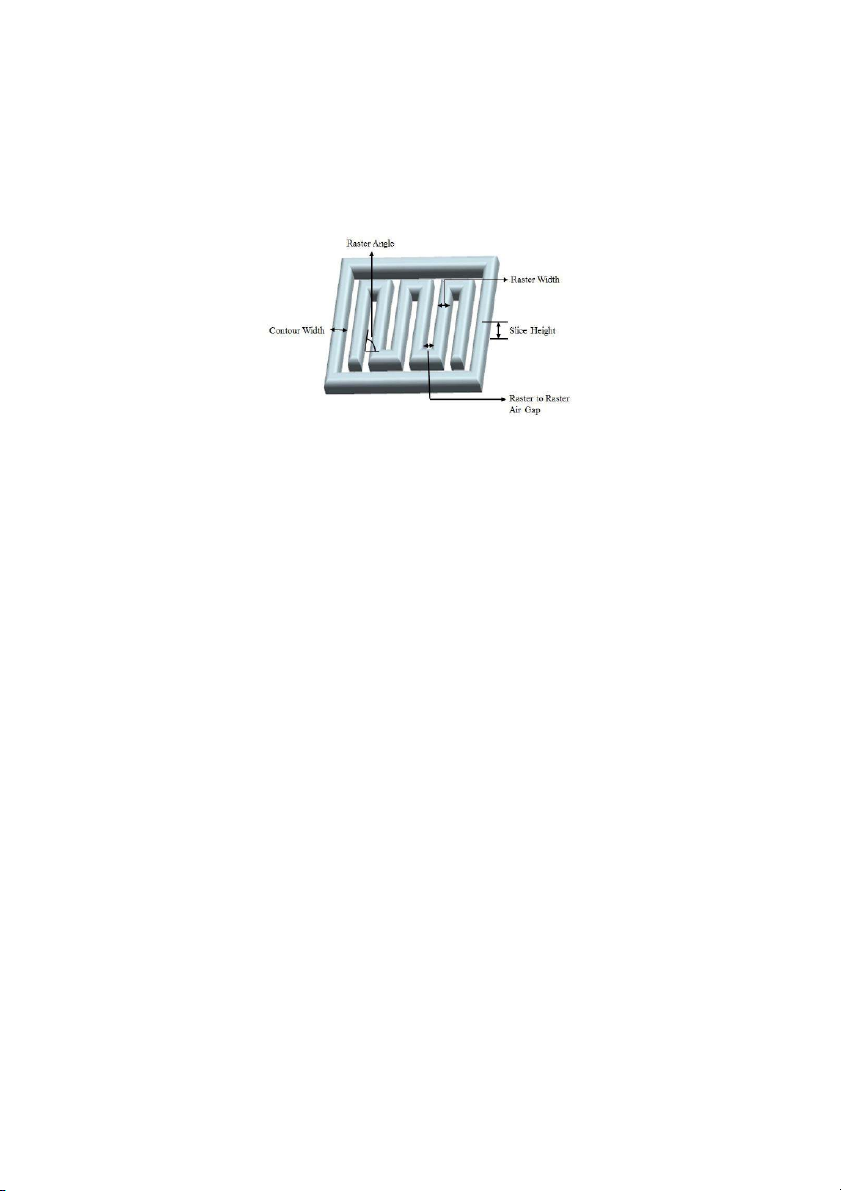
performance and production economics of a material extrusion AM part. Infill design
contour is defined as the solid perimeter walls in each layer. This is varied by changing
the number of walls and/or the thickness of each contour. Another infill parameter is the
spacing between contour and raster, and infill pattern, as shown in Figure 2.
Study of infill print design on production cost-time of 3d printed ABS parts 311
Figure 2 Insight® build parameters
Source: Hossain et al. (2013)
A study on the effects of layer thickness, print orientation and raster angle indicated that
greater layer thickness provides better mechanical properties if printed in the x and z
directions, and lower layer thickness is ideal for y direction (Bagsik and Schöppner,
2011). Another study compared mechanical properties for different air gap, cap thickness
and wall thickness, and found that cap thickness is the most important parameter in
flexural strength, and higher air gap increases strength to weight and modulus to weight
ratios (Iyibilgin et al, 2014). It was reported that wall thickness has no clear effect on the
strength. Another study compared the raster width, contour width and air gap at different
raster angles and found that lower contour width and raster width increase Ultimate
Tensile Strength (UTS) (Hossain et al., 2013). Further, lower contour width and raster
width along with negative air gap resulted in higher UTS. Another approach compared
the compressive strengths of lattice infill structures when compared to default infill
densities (Iyibilgin et al, 2013). The mechanical properties of honeycomb lattice infill
structures were significantly better than sparse and double-dense infill designs. The yield
stress of honeycomb infill design was 217% and 253% higher than double-dense and
sparse, respectively. In addition, compressive modulus of honeycomb structure was
286% and 579% higher than double-dense and sparse, respectively.
Past studies on the effects of infill design clearly demonstrate the need to compare
infill design and mechanical properties. However, there is also a need to correlate
mechanical properties of infill designs with production time and associated cost. The
main focus of this study is to evaluate various infill patterns against the baseline of solid
infill pattern. This work primarily aims to develop a comprehensive framework for ‘print
design–mechanical properties–cost estimation’ based on practical applications. This
understanding will aid in the analysis of correlation between cost and time based on infill
design and desired mechanical properties. For instance, one infill design could be more
appropriate for tensile load but not the ideal design if the part is subjected to a bending
load. It should be noted that although this work used a production-grade printer and
partial infill parameter combinations, the proposed methodology can be adapted for other
entry-level material extrusion systems and/or infill parameters. Hence, a preliminary
trend analysis is conducted to analyse impact of cost variation between different printers. 312
L. Baich, G. Manogharan and H. Marie 3 Methodology
The material extrusion AM machine used in this study was Stratasys Fortus 250mc using
ABSplus-P430 (Acrylonitrile Butadiene Styrene) with a T14 nozzle tip and a layer
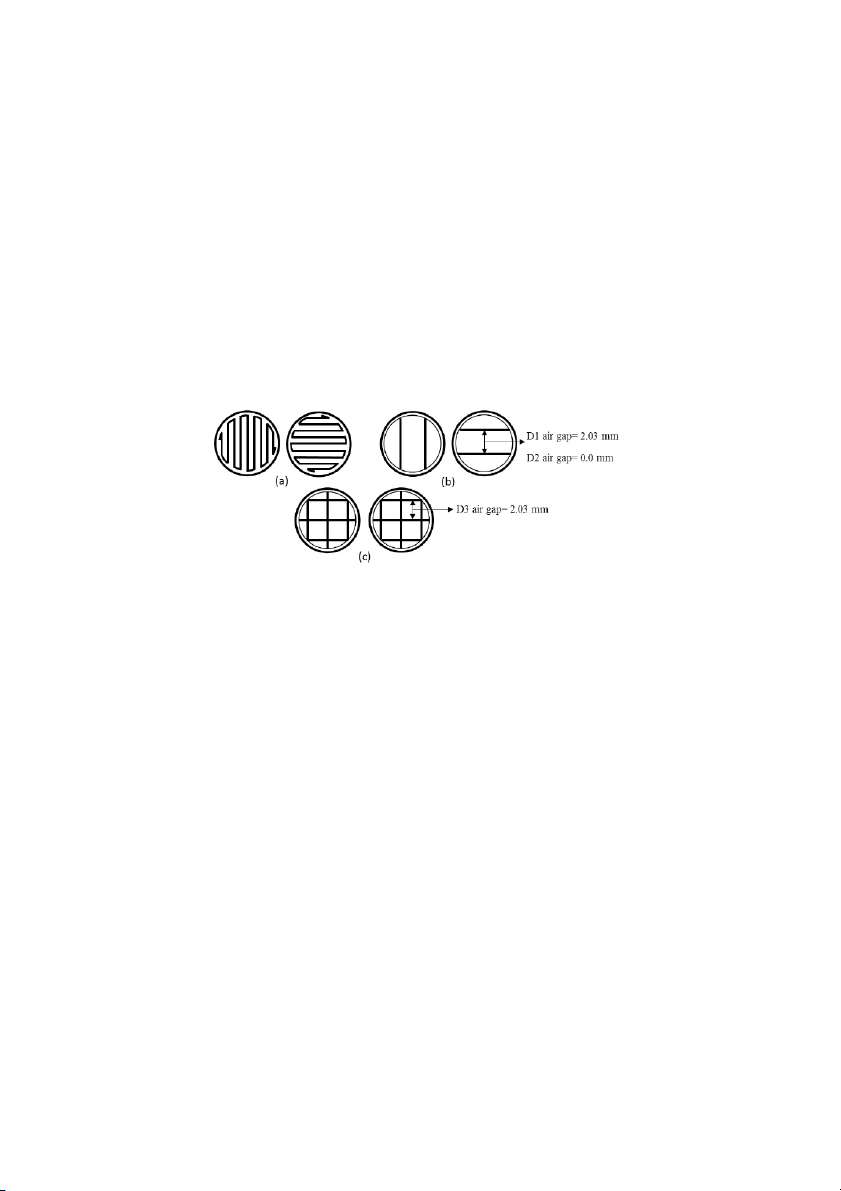
thickness of 0.254 mm. Infill print parameters used in the study include D1 (low), D2
(high), D3 (double dense) and D4 (solid) infill patterns as shown in Figure 3. The air gap
for D1, D2, D3 and D4 are 2.03, 0, 2.03 and –0.03 mm, respectively. D4 has a negative
air gap which makes the specimen completely solid. Other infill design parameters for all
densities were uniform with a cap thickness of 1.16 mm (top and bottom) and a wall thickness of 0.508 mm.
Figure 3 FDM build styles: (a) solid build (D4); (b) sparse build (D1 and D2);
(c) sparse–double-dense build (D3)
Source: Iyibilgin et al. (2014)
The specimens were designed based on ASTM standards with nominal dimensions of
(1) tensile type I, width = 13 mm, thickness = 3.2 mm, gage length = 57 mm, overall
length = 165 mm; (2) compression, width = 12.7 mm, thickness = 25.4 mm, length =
12.7 mm; and (3) bending, width = 12.7 mm, thickness = 3.2, length = 127 mm. The
tensile and bending specimens were printed along the x axis, while the compression
specimens were printed along the y axis. Mechanical testing was conducted using Instron
Model 5967 with 30 kN maximum load capacity and an accuracy of ±0.25% of full load
based on ASTM Tensile D638, Compression D695 and Flexural D790 test requirements.
Test speeds varied as follows: Tensile: 5 mm/min; Compression: 1.3 mm/min; and
Flexural: 0.5 mm/min (ASTM D638, 2014; ASTM D695, 2010; ASTM D790, 2010).
The specimen dimensions were measured before testing using a digital caliper with an
accuracy of ±0.01 mm. Three samples per infill design were tested for each loading
condition. In addition, cost per sample was determined for each ASTM specimen. The
total cost per sample included the material cost (feed stock cost × material volume) and
the production cost (print cost × print time). Since set-up and part retrieval times are
uniform for all print specimens, they were not included in the print time and thus not in
the production cost. The feed stock cost was uniform at 0.028 cents/mm3, based on a
standard spool price of $260 for a volume of 922,600 mm3. For the Stratasys Fortus
250mc equipment, the print cost was determined to be $0.50/min. Therefore, total cost
variation in the different ASTM and infill design specimens was owing to the material
volume used and corresponding print time. Finally, in addition to the comparative infill
Study of infill print design on production cost-time of 3d printed ABS parts 313
study, a preliminary cost sensitivity analysis was conducted with respect to usage costs
and specimen volume. This was applied to low-density infill tensile specimen and
allowed for the variation of different types of printers and different size specimens. The
specimen was scaled to a range of 10–550% of the original ASTM tensile specimen. The
total cost, as a function of material volume and print cost, was determined. 4 Results and analysis
The average print time (minutes) and material volume (mm3) for all the specimens with
different infill design is shown in Table 1. It should be noted that in general the double-
dense infill (D3) had the longest print time and the high-density infill (D2) required the
most material. This is attributed to the alternate direction of raster on each layer. Using
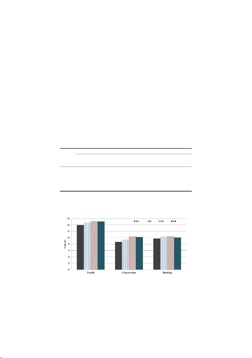
the values in Table 1, the total unit cost for each ASTM sample and infill design was
determined and is presented in Figure 4. It can be observed that double dense (D3) is the
most expensive infill design since print cost (Fortus 250mc) is more significant than material cost. Table 1
Print time and material consumption Tensile Compression Bending Density Material Print Material Print Material Print time % % % volume time volume time volume (min) porosity porosity porosity (mm3) (min) (mm3) (min) (mm3) Low (D1) 24 6882.56 23.63 16 2458.05 42.31 17 4424.50 20.59 High (D2) 25 8029.66 10.91 17 3277.41 23.10 18 4916.11 11.76 Double 26 7374.17 18.18 19 2949.67 30.77 18 4916.11 11.76 dense (D3) Solid (D4) 25 9012.88 – 18 4260.63 – 17 5571.60 –
It is also noted that the costs of double-dense (D3) and solid (D4) infill were similar for
tensile specimens and costs of high-density (D2) and double-dense (D3) infill were
similar for bending specimens.
Figure 4 Total cost for different infill designs 314
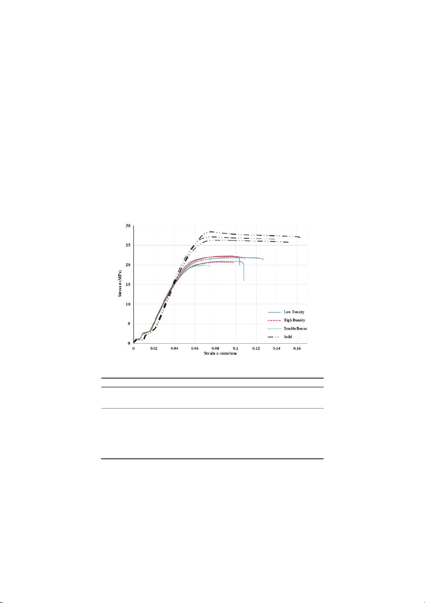
L. Baich, G. Manogharan and H. Marie 4.1 Tensile
The stress strain characteristics for tensile specimens with different infill patterns are
shown in Figure 5 with the average mechanical properties summarised in Table 2. The
plot shows that as expected the solid (D4) infill specimens had the highest modulus of
elasticity and UTS, as expected. It is particularly interesting to note that double-dense
(D3) infill design has lower UTS than both low-density infill (lesser material volume,
shorter print time) and high-density (D2) infill (higher material volume). Even though
double dense infill had lower UTS than low-density and high-density infill, the stress–
strain behaviours were very similar for all three in-fill designs. This shows that when a
printed part is subject to tensile load, double dense is not the most desirable infill design.
This is counter-intuitive in terms of additional material consumption in double-dense infill design.
Figure 5 Tensile–stress versus strain Table 2
Mechanical properties of infill designs Tensile Compression Bending Compressive Flexural Modulus, E Modulus, E Modulus, Density UTS (MPa) strength strength (MPa) (MPa) E (MPa) (MPa) (MPa) Low (D1) 21.64 486.45 23.79 624.55 32.85 456.68 High (D2) 21.71 542.04 27.77 824.28 34.42 459.83 Double dense (D3) 20 511.68 31.09 850.52 36.9 554.41 Solid (D4) 27.27 638.79 56.76 1191.98 43.75 573.06 Average % 2.88 4.16 7.16 6.85 2.32 5.23 Std. Dev
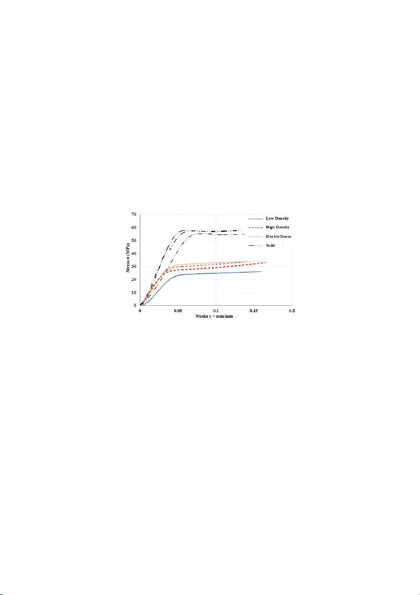
Study of infill print design on production cost-time of 3d printed ABS parts 315 4.2 Compression
The stress versus strain behaviour of compression specimens is shown in Figure 6 with
the average mechanical properties summarised in Table 2. Overall, this type of loading
had the least consistent material properties, both within an infill design and across
different infill designs. The largest variation is seen in the compressive modulus across
infill designs, indicating that this property is the most dependent on infill pattern. It was
noted that low-density (D1) and double-density (D3) infill specimen groups were the
most consistent. It was also observed that high-density and double-dense specimens had
very similar modulus of elasticity. The compressive strength results were as expected
based on infill densities in that as the complexity of the infill pattern increased, the
compressive strength increased.
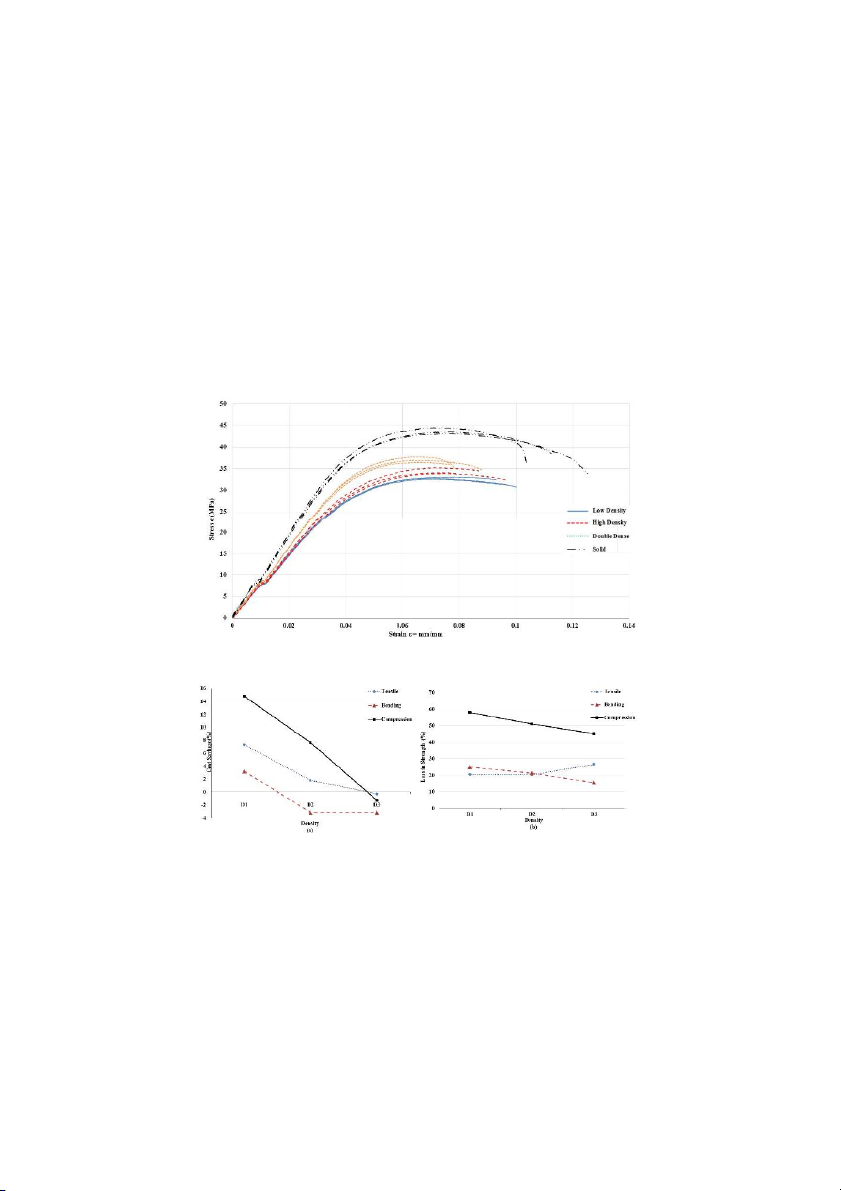
Figure 6 Compression stress versus strain 4.3 Flexural
The stress–strain behaviour of bending specimens is shown in Figure 7 with the average
mechanical properties summarised in Table 2. It is evident that specimens exhibited
highly repeatable material properties within each infill design. The flexural strength
results were as expected with respect to infill complexity, with solid (D4) and low-
density (D1) infill having the highest and lowest UTS, respectively. It was also observed
that low-density (D1) and high-density (D2) infill flexural strengths were very similar;
the implication of this is discussed in the cost analysis. 4.4 Cost analysis
Figures 8(a) and 8(b) show cost savings (%) and reduction in strength (%), respectively,
of infill groups for tensile, bending and compression when compared to solid infill
specimens. Higher reduction in cost (%) means greater cost savings and higher reduction
in mechanical strength (%) means greater loss in mechanical strength, both with respect
to solid infill. For instance, during tensile loading, there was no loss in strength between 316
L. Baich, G. Manogharan and H. Marie
low- and high-density infill specimens, but low density infill provides a larger cost
savings. Interestingly, the double-dense infill tensile specimen exhibited the greatest loss
in strength but had the least cost savings. In the case of bending, it was noted that there
were minor differences in strength between low- and high-density infill specimens, while
again low-density infill provided the largest cost savings. It was also observed in bending
conditions that while the loss in strength decreased from high-density infill to double-
dense infill, the cost savings (which is actually a cost increase) for these two were
similar. In the case of compression, loss in strength as well as cost savings decrease
linearly as the complexity of the infill pattern increases from low- to high-density infill to double-dense infill design.
Figure 7 Bending stress versus strain
Figure 8 (a) % in cost savings; (b) % average loss in strength when compared to solid
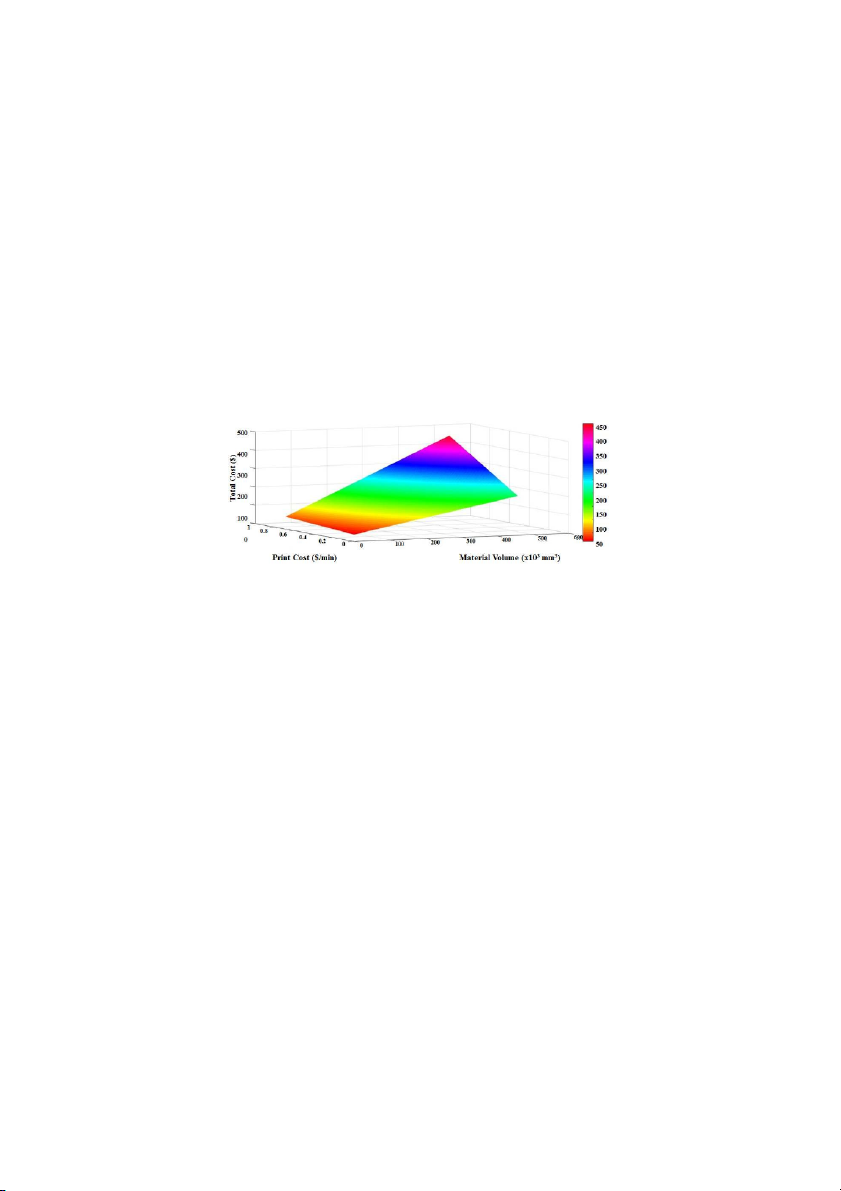
Finally, the preliminary cost sensitivity analysis with respect to print costs and material
volume is shown in Figure 9. Low-density tensile specimens were chosen because they
were the largest of the ASTM samples, so the results would have the largest effect on
print time and material consumption, as would be the case in practical applications. The
Study of infill print design on production cost-time of 3d printed ABS parts 317
print cost used in this portion of the study had a range of $0.15–0.85/min in order to
account for a range of printers from entry level to production grade. Note that previously
the print cost was a constant $0.50/min to account for printing in Fortus 250mc. Since
part size is another critical variable, a range of 10–550% of the previous constant part
volume (6882.56 mm3) was considered in this analysis. This affected both material
consumption and print time. As shown in Figure 9, the unit cost was more sensitive to
part volume than print cost. When compared to baseline conditions, the increase in unit
cost of the part caused owing to larger part size ranged from 2830% (production-grade
printer) to 4380% (entry-level printer). In contrast, when the part was scaled down to
10% of original volume, the unit cost increased by 460% when print cost was upgraded
from entry-level to production grade printer. In the case of scaling up of the part by
550%, the unit cost increased only by 140% with upgrade to production grade printer.
Figure 9 Print cost ($/min) versus material volume (mm3) versus total cost ($) 5 Conclusion
With growing number of AM printers (specifically material extrusion), it is expected that
print cost and material cost will continue to decrease. This study identified print cost had
more impact on production cost than material cost. Hence, in the case of entry-level
printers, solid infill is recommended for mechanical applications. The results
demonstrated that for tensile loading, low density had cost savings with similar strength
performance to high density. For bending applications, low density had significant cost
savings with minimal loss in strength. Double dense is also favourable over high density
for bending because it provides a larger gain in strength but the cost remains the same
between high-density and double-dense infill designs. It was also found that solid infill
design had higher strength when compared to high-density infill design with similar
production cost. Compression testing revealed a linear relationship between material
volume and cost-strength performance. In the case of double-dense infill, for all loading
conditions, solid infill had greater strength at the same production cost. Additional
analysis on ‘custom’ infill pattern with respect to mechanical loading is required (similar
to directional grain growth in metal parts). It will be beneficial to incorporate Finite
Element Analysis (FEA) to correlate mechanical testing for different loading conditions
with custom infill design along with production cost constraints. While the preliminary 318
L. Baich, G. Manogharan and H. Marie
cost sensitivity analysis provided a framework for investigating factors contributing to
part cost, additional work is required to identify the correlation of these factors based on
specific part design for different loading applications. References
ASTM D638 (2014) ASTM D638 - 14: Standard Test Method for Tensile Properties of Plastics,
ASTM International, West Conshohocken, PA. Available online at: www.astm.org.
ASTM D695 (2010) ASTM D695 - 10: Standard Test Method for Compressive Properties of Rigid
Plastics, ASTM International, West Conshohocken, PA. Available online at: www.astm.org.
ASTM D790-10 (2010) ASTM D790 - 10: Standard Test Methods for Flexural Properties of
Unreinforced and Reinforced Plastics and Electrical Insulating Materials, ASTM
International, West Conshohocken, PA. Available online at: www.astm.org.
ASTM F2792 (2012) ASTM F2792 - 12a: Standard Terminology for Additive Manufacturing
Technologies,, ASTM International, West Conshohocken, PA. Available online at: www.astm.org.
Bagsik, A. and Schöppner, V. (2011) ‘Mechanical properties of fused deposition modeling parts
manufactured with Ultem∗9085’, Proceedings of the 69th Annual Technical Conference of the
Society of Plastics Engineers, 1–5 May, Boston, MA, pp.1294–1298.
Bak, D. (2003) ‘Rapid prototyping or rapid production? 3D printing processes move industry
towards the latter’, Rapid Prototyping Journal, Vol. 23, pp.340–345.
Boschetto, A. and Bottini, L. (2014) ‘Accuracy prediction in fused deposition modeling’,
International Journal of Advanced Manufacturing Technology, Vol. 73, pp.913–928.
Conner, B.P., Manogharan, G.P., Martof, A.N., Rodomsky, L.M., Rodomsky, C.M., Jordan, D.C.
and Limperos, J.W. (2014) ‘Making sense of 3-D printing: creating a map of additive
manufacturing products and services’, Additive Manufacturing, Vols. 1–4, pp.64–76.
Fischer, F. (2015) Thermoplastics: the best choice for 3D printing, Stratasys, pp.1–5. Available online at:
http://www.appliancedesign.com/ext/resources/AM/Home/Files/PDFs/
themoplastics.pdf (accessed on 14 June 2015).
Guo, N. and Leu, M.C. (2013) ‘Additive manufacturing: technology, applications and research
needs’, Frontiers of Mechanical Engineering, Vol. 8, pp.215–243.
Hossain, M.S., Ramos, J., Espalin, D., Perez, M. and Wicker, R. (2013) ‘Improving tensile
mechanical properties of FDM-manufactured specimens via modifying build parameters’,
Proceedings of the 24th International Solid Freedom Fabrication Symposium on Additive
Manufacturing, 12–14 August, Austin, TX, pp.380–392.
Iyibilgin, O., Yigit, C. and Leu, M.C. (2013) ‘Experimental investigation of different cellular
lattice structures manufactured by fused deposition modeling’, , Proceedings of the 24th
International Solid Freedom Fabrication Symposium on Additive Manufacturing, 12–14 August, Austin, TX, pp.895–907.
Iyibilgin, O., Leu, M.C., Taylor, G., Li, H. and Chandrashekhara, K. (2014) ‘Investigation of
sparse-build rapid tooling by fused deposition modeling’, Proceedings of the 25th
International Solid Freedom Fabrication Symposium on Additive Manufacturing, 4–6 August, Austin, TX, pp.542–556.
Jauhar, S., Asthankar, K.M. and Kuthe, A.M. (2012) ‘Cost benefit analysis of rapid manufacturing
in automotive industries’, Advances in Mechanical Engineering and Its Applications, Vol. 2, pp.181–188.
Kumar, G.P. and Regalla, S.P. (2014) ‘DOE-based parametric study of volumetric change of FDM
parts’, Procedia Materials Science, Vol. 6, pp.354–360.
Study of infill print design on production cost-time of 3d printed ABS parts 319
Pei, E., Campbell, R.I. and Beer, D. (2011) ‘Entry-level RP machines: how well can they cope with
geometric complexity?’ Assembly Automation, Vol. 31, pp.153–160.
Petrick, I.J. and Simpson, T.W. (2013) ‘3D printing disrupts manufacturing: how economies of one
create new rules of competition’, Research-Technology Management, Vol. 56, pp.12–16.
Solid Concepts (2015) Fused deposition modelling, pp.1–8. Available online at: https://www.
solidconcepts.com/content/pdfs/brochures/fused-deposition-modeling-fdm-brochure.pdf (accessed on 16 June 2015).
Tài liệu liên quan:
-

Đồ án liên môn gồm 3 sản phẩm ( nhãn - hộp- tạp chí)
8 4 -

Bài giảng Quy trình sản xuất ấn phẩm môn Công nghệ in | Trường Đại học Sư phạm Kỹ thuật Thành phố Hồ Chí Minh
42 21 -

Bài giảng Tổng quan về các phương pháp in dùng khuôn in môn Công nghệ in | Trường Đại học Sư phạm Kỹ thuật Thành phố Hồ Chí Minh
41 21 -
Tìm hiểu về các sản phẩm bao bì in bởi công nghệ in Offset và xu hướng phát triển | Môn Công nghệ in - Đại học Sư phạm Kỹ thuật Thành phố Hồ Chí Minh
110 55 -
Tìm hiểu độ bền chà xát của các sản phẩm bao bì giấy in bằng phương pháp in Offset | Môn Công nghệ in - Đại học Sư phạm Kỹ thuật Thành phố Hồ Chí Minh
110 55