Tiểu luận môn Dung sai và kỹ thuật đo đề tài "Scan 3D machine and coordinate measuring machine (CMM)"
Tiểu luận môn Dung sai và kỹ thuật đo đề tài "Scan 3D machine and coordinate measuring machine (CMM)" của Đại học Sư phạm Kỹ thuật Thành phố Hồ Chí Minh với những kiến thức và thông tin bổ ích giúp sinh viên tham khảo, ôn luyện và phục vụ nhu cầu học tập của mình cụ thể là có định hướng ôn tập, nắm vững kiến thức môn học và làm bài tốt trong những bài kiểm tra, bài tiểu luận, bài tập kết thúc học phần, từ đó học tập tốt và có kết quả cao cũng như có thể vận dụng tốt những kiến thức mình đã học vào thực tiễn cuộc sống. Mời bạn đọc đón xem!
Môn: Dung sai & Kỹ thuật đo (TOMT220225) 12 tài liệu
Trường: Trường Đại học Sư phạm Kỹ thuật Thành phố Hồ Chí Minh 4.4 K tài liệu
Tác giả:


Preview text:
lOMoARcPSD|36625228 TABLE OF CONTENTS lOMoARcPSD|36625228
CHAPTER 1: SCAN 3D MACHINE . . . . . . . . . . . . . . . . . . . . . . . . . . . . . . . . 1
1.1. The 3D scanning machine concept: . . . . . . . . . . . . . . . . . . . . . . . . . . . . . . 1
1.2. Advantages & Disadvantages of 3D scanners . . . . . . . . . . . . . . . . . . . . . . 1
1.3. Popular types of 3D scanning technology . . . . . . . . . . . . . . . . . . . . . . . . . 2
1.4. Application in the life of 3D Scanners: . . . . . . . . . . . . . . . . . . . . . . . . . . . 7
1.5. Structure of a 3D scanner machine . . . . . . . . . . . . . . . . . . . . . . . . . . . . . 10
1.6. Working principle of scan3D machine: . . . . . . . . . . . . . . . . . . . . . . . . . . 11
1.7. Technical requirements of a 3D scanner machine . . . . . . . . . . . . . . . . . . 11
1.8. Maintenance instructions of Scan 3D machine . . . . . . . . . . . . . . . . . . . . 12
CHAPTER 2: COORDINATE MEASURING MACHINE (CMM) . . . . . . 14
2.1. Coordinate Measuring Machine concept . . . . . . . . . . . . . . . . . . . . . . . . . 14
2.2. Advantages & Disadvantages of Coordinate Measuring Machine . . . . . 14
2.3. Classification of Coordinate Measuring Machines (CMM) . . . . . . . . . . 15
2.4. Structure of Coordinate Measuring Machine . . . . . . . . . . . . . . . . . . . . . 26
2.5. Uses of Coordinate Measuring Machines (CMM) . . . . . . . . . . . . . . . . . 28
2.6. Working principle of Coordinate Measuring Machines (CMM) . . . . . . 29
2.7. Application of Coordinate Measuring Machines (CMM) . . . . . . . . . . . . 31
2.8. Maintenance instructions of Coordinate Measuring Machines (CMM) . 31
REFERENCE MATERIALS. . . . . . . . . . . . . . . . . . . . . . . . . . . . . . . . . . . . . . . .
CHAPTER 1: SCAN 3D MACHINE
1.1. The 3D scanning machine concept:
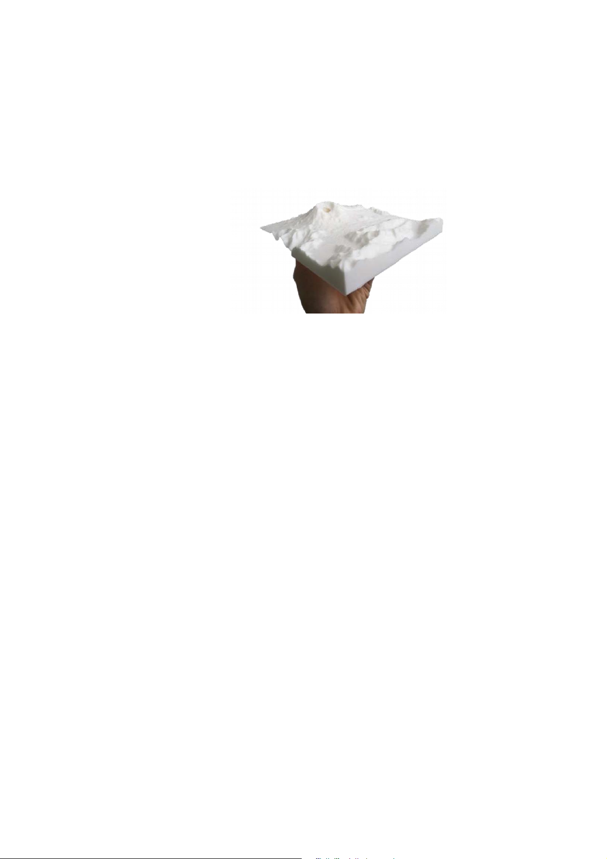
3D scanning machine is understood as a method to help capture physical objects in the
form of 3D geometry (CAD). 3D scanning machine is one of the major breakthroughs
in the industrial revolution 4.0. Thanks to this technology, it is now extremely easy to
create products with high accuracy relative to samples. lOMoARcPSD|36625228
Fig 1.1: 3D scanning concept
3D scanning machine is a process that determines the surface shape of an object in
three dimensions to create a 3D digital model. Scanning 3D objects has opened a new
turning point in 3D technology.
Thanks to 3D scanning, any physical model that exists in the world can be
modeled with digital data in a short time. Thanks to its high applicability, this
technology is applied in many fields from manufacturing, mechanics, archeology, and
health to transportation and construction. .
1.2. Advantages & Disadvantages of 3D scanners Advantages of 3D Scanners:
• Precise and Accurate: 3D scanners can capture highly precise and accurate
measurements of an object or environment, which can be useful for creating detailed plans or models.
• Efficient: Automated 3D scanning processes can be much more efficient than
traditional measuring techniques, which can save time and reduce costs.
• Non-invasive: Many 3D scanning techniques are non-invasive, which means they do
not require physical contact with the object or the environment. This reduces the risk of
damage or alteration to the object or environment during the scanning process.
• Versatile: 3D scanning can be used in a wide range of applications across various
industries, including architecture, engineering, healthcare, and manufacturing. lOMoARcPSD|36625228
• Cost-effective: Some 3D scanning techniques, such as photogrammetry, can be less
expensive than other 3D scanning techniques, making them more accessible to industries or
individuals with limited budgets. Disadvantages of 3D Scanners:
• High cost: some 3D scanners are expensive and require skilled professionals to
operate them, which can increase the cost of implementing a 3D scanning program.
• Data processing: Collecting and processing 3D data can be time-consuming, and
software to process the data can also be expensive.
• Limited resolution: some 3D scanners have limited resolution, which means they may
not be suitable for capturing detailed or complex objects.
• Safety concerns: Certain types of 3D scanners, such as those that use X-ray or
Gamma rays, can pose a safety risk or require special precautions to use safely.
• Specialized knowledge: Some 3D scanning techniques require specialized knowledge
or training, which may not be accessible to all users.
Overall, while 3D scanners have many advantages, users should be aware of
potential disadvantages and limitations in order to make informed decisions about
which type of scanner or technique is well suited for their specific needs.
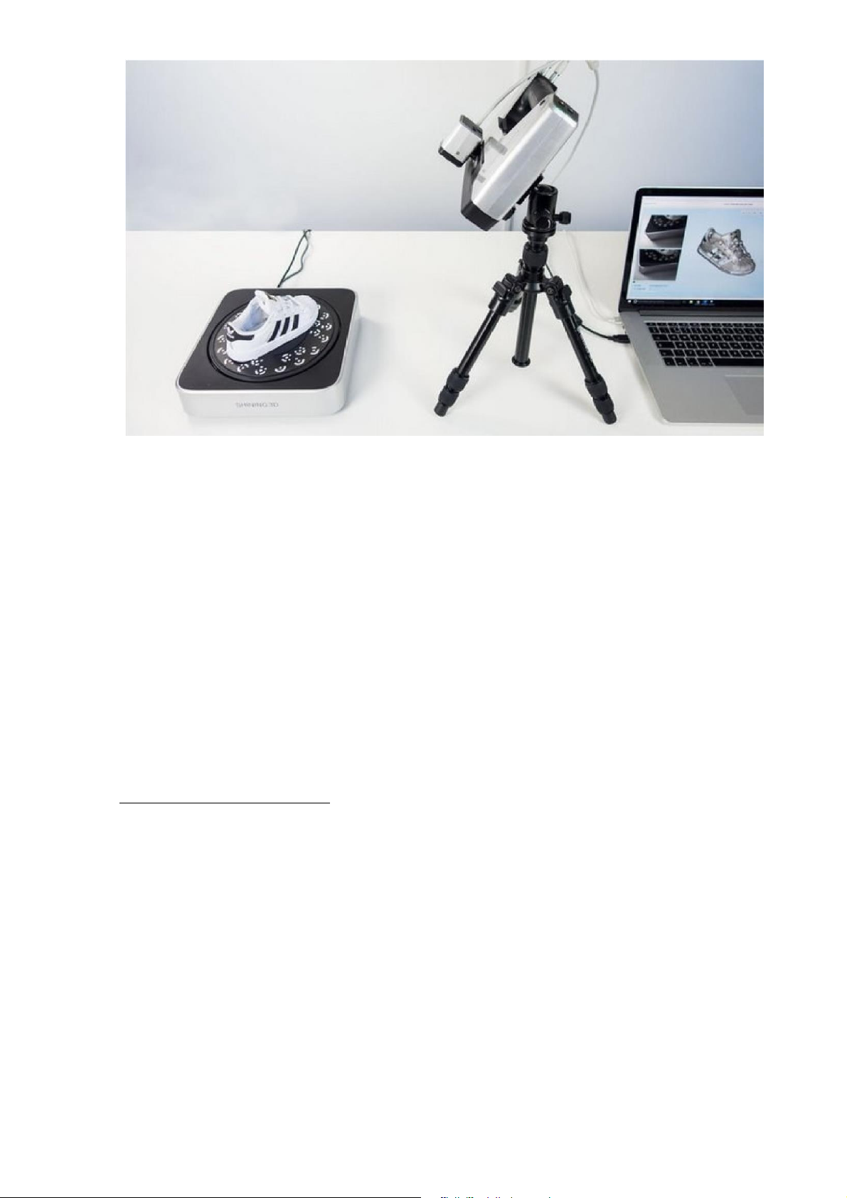
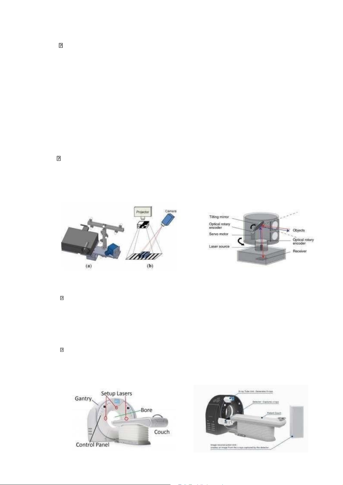
1.3. Popular types of 3D scanning technology Structured-light 3D scanner:
A structured-light 3D scanner is a type of 3D scanning device that uses projected
light patterns to capture the 3D geometry of objects or environments. This method
involves projecting a known pattern of light onto the subject, which is captured by one
or more cameras from different angles. The distortion of the pattern on the object's
surface due to its shape is then used to calculate the 3D coordinates of each point on the surface. lOMoARcPSD|36625228
Fig 1.2: Structured-light 3D scanner
The pattern can take various forms, such as grids, stripes, or dots, and can be either
static or dynamic. With dynamic patterns, projections are quickly switched, allowing
for faster scans with a higher level of detail.
Structured-light scanners can be used to scan small to medium-sized objects and
are often used in manufacturing, rapid prototyping, reverse engineering, and quality
control. They are also used in cultural heritage preservation, medical imaging, and
virtual and augmented reality applications. The benefits of structured-light 3D
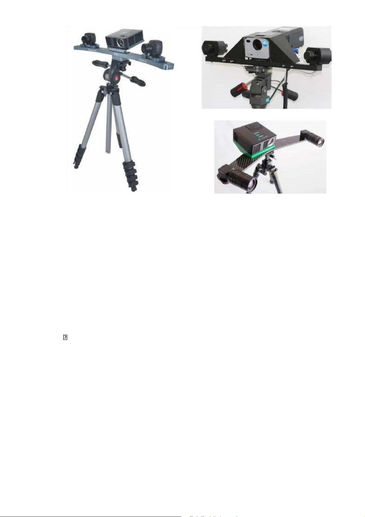
scanners include fast scan times, high levels of accuracy, and ease of use. Laser 3D scanner:
This technology works by emitting laser beams onto the surface of an object. Next
record the data of the laser on the object surface by the sensor. Easier to understand,
when the laser is projected onto the surface of an object with a clear low altitude, the
output data will be the low altitude of that laser. Laser 3D scanning technology has
been developed through product lines such as handheld 3D scanners. lOMoARcPSD|36625228
Fig 1.3: 3D scanning with laser
A Laser 3D scanner is a device that uses laser technology to capture the
threedimensional shape of an object or environment. The scanner emits laser light onto
the surface of the object and measures the time it takes for the reflected light to return
to the scanner. Based on this information, the scanner can calculate the distance from
the scanner to the object surface at each point, creating a point cloud of the object’s surface.
This point cloud can then be processed by specialized software to generate a 3D
model of the object. Laser 3D scanners typically have high accuracy and can capture
fine details, making them ideal for applications such as reverse engineering, quality
control, and inspection in manufacturing industries.
Laser 3D scanners come in different types, such as handheld, tripod-mounted, or
robotic arm-mounted, each with its own strengths and limitations. They are also used
in applications such as cultural heritage preservation, medical imaging, and virtual and
augmented reality. Some of the key benefits of laser 3D scanning include high
accuracy, fast scanning speeds, and the ability to capture complex shapes and fine
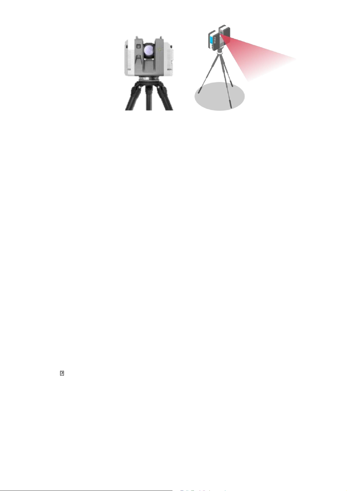
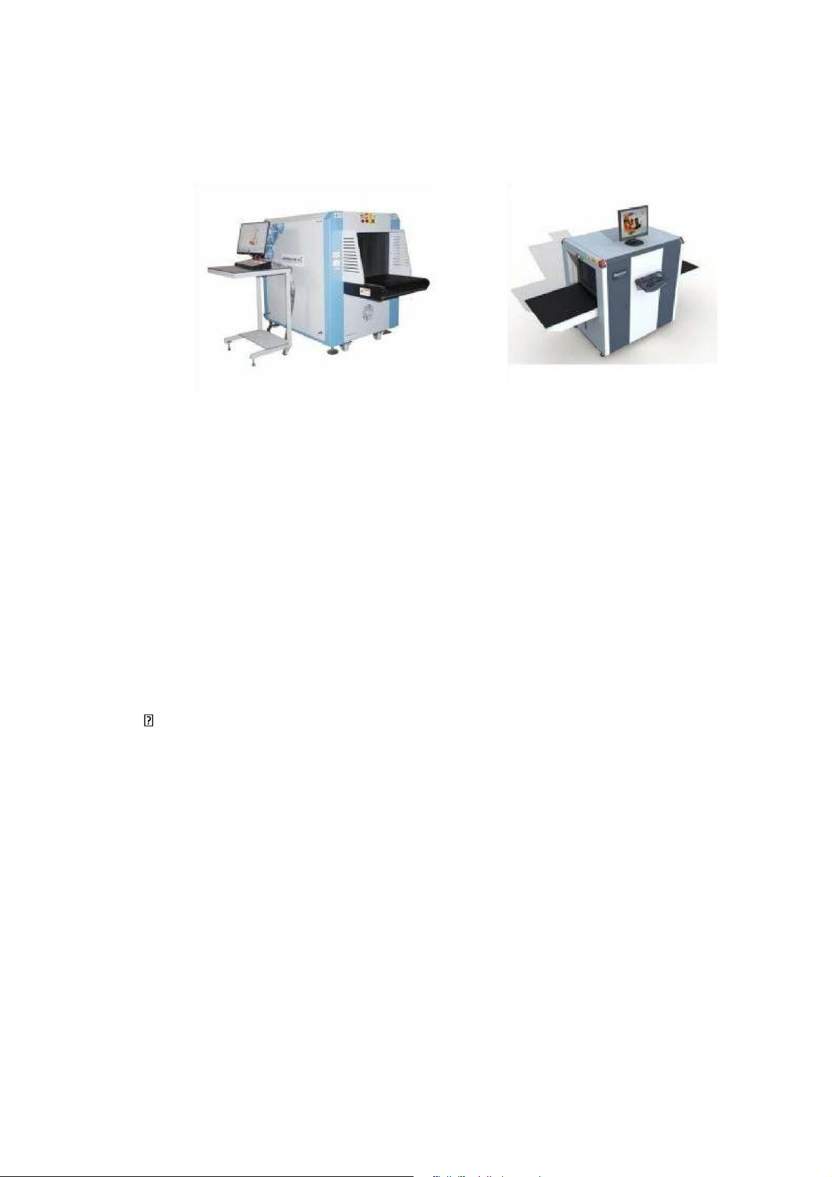
details that may be difficult or impossible to measure with traditional methods X-ray 3D scanner:
An X-ray 3D scanner is a device that uses X-ray technology to capture the
threedimensional structure of an object's internal components. The scanner emits
Xrays, which pass through the object and are detected by a sensor on the opposite side.
The image captured by the sensor, in combination with specialized software, is used to
create a 3D model of the object's internal structure. lOMoARcPSD|36625228
X-ray 3D scanners are often used in the fields of non-destructive testing and
industrial inspection to detect flaws, voids, or other internal defects in materials that
may be difficult or impossible to detect using other methods. They are also widely
used in medical imaging to produce three-dimensional images of the human body.
Fig 1.4: X-ray 3D scanner
One of the key advantages of X-ray 3D scanning is the ability to capture accurate
and precise data on the internal structure of objects without damaging or altering them.
However, X-ray 3D scanning does involve a small amount of radiation exposure, so it
must be used with discretion and safety protocols in place.
Overall, X-ray 3D scanners are an effective tool for obtaining detailed and accurate
data on the internal structure of objects, and have a wide range of applications in
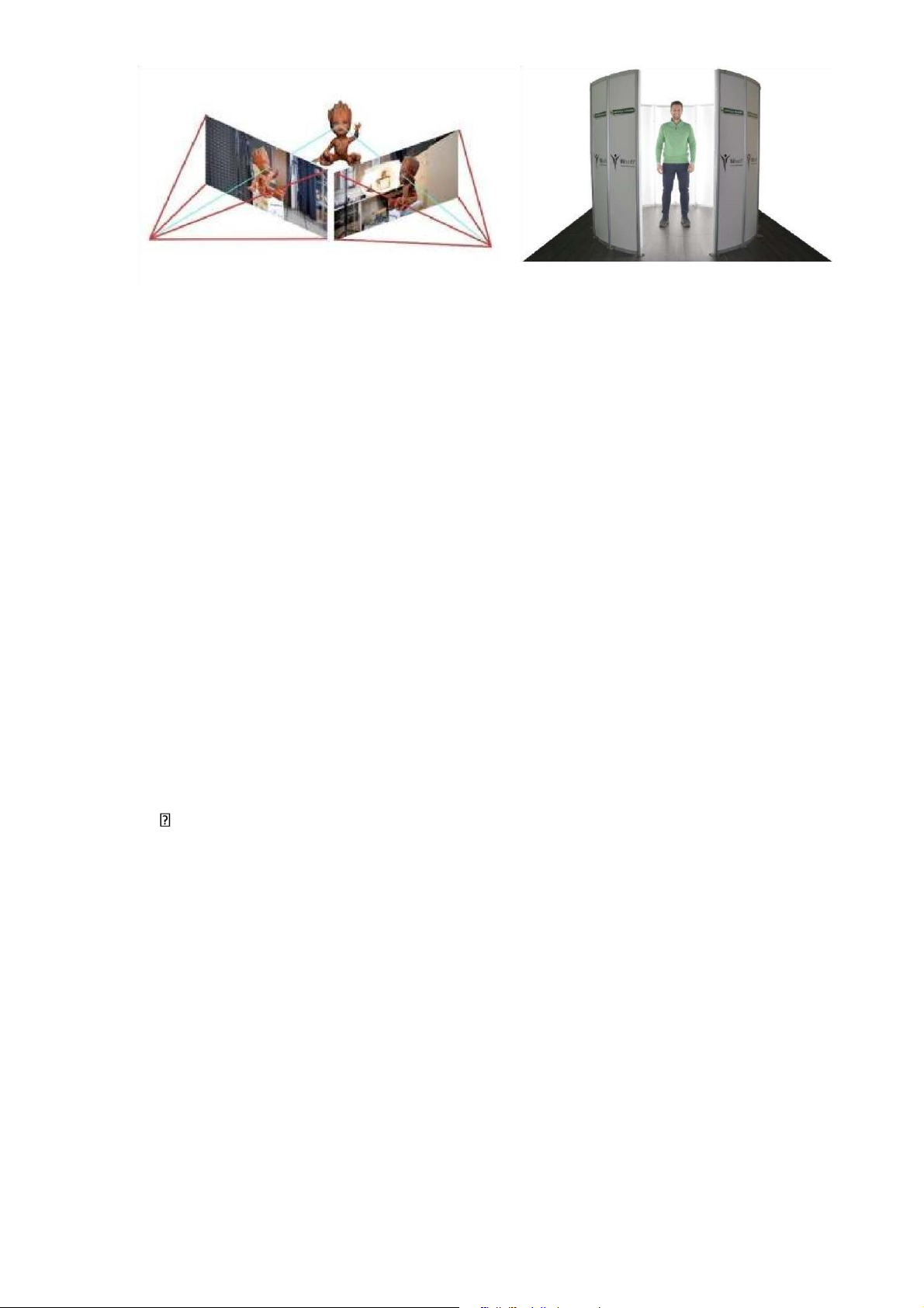
various industries, including manufacturing, aerospace, agriculture, and medical imaging. Photogrammetry 3D scanner:
Photogrammetry 3D scanning is a process of capturing three-dimensional data
using photographic images. This process involves taking multiple photographs of an
object or environment from different angles and positions and then using software to
analyze the images to generate a 3D model.
The software uses various techniques such as triangulation, feature matching, and
perspective analysis to identify corresponding points in the images and calculate their
relative positions. Using this process, the software can generate a 3D point cloud,
which can be further processed to create a 3D model. lOMoARcPSD|36625228
Fig 1.5: Photogrammetry 3D scanner
Photogrammetry 3D scanning can be done using a single camera or multiple
cameras, which can be either fixed or mobile. It is often used in surveying,
architectural design, cultural heritage, and virtual reality applications. It can also be
used in the film and video game industry for creating realistic visual effects and environments.
One of the main advantages of photogrammetry 3D scanning is that it can capture
a large amount of data quickly and efficiently, making it ideal for scanning large areas
or objects. It can also be less expensive compared to other 3D scanning techniques, as
it does not require specialized equipment.
Overall, photogrammetry 3D scanning is a versatile and effective tool for
capturing three-dimensional data from photographic images, and it has a wide range of
applications in various industries. Thermal 3D scanner:
A thermal 3D scanner is a device that uses infrared technology to capture a
threedimensional representation of an object or environment based on the surface
temperature of the object. The scanner emits infrared radiation that is reflected and
absorbed by the object, and a sensor measures the amount of heat given off in each location.
Using specialized software, the thermal data is processed to create a 3D model of
the object or environment, with variations in temperature represented by changes in
color. This makes it possible to see the temperature differences across different
surfaces, which can be useful in identifying defects, monitoring temperatures, and
detecting objects that are not visible to the naked eye. lOMoARcPSD|36625228
Thermal 3D scanners are often used in industries such as construction,
manufacturing, and energy, where it is important to detect defects or temperature
variations that could cause equipment failure or safety hazards. They are also used in
medical imaging, specifically in the evaluation of musculoskeletal conditions.
One of the key benefits of thermal 3D scanning is its ability to detect temperature
variations in real time, making it an efficient way to monitor and diagnose potential
issues. Additionally, it is a non-contact method, which means that equipment or
components do not need to be physically touched or adjusted during the scanning process.
Overall, thermal 3D scanners are a valuable tool for identifying defects, detecting
potential problems, and monitoring systems in real time across a variety of industries.
1.4.Application in the life of 3D Scanners:
3D scanners have a wide variety of applications in various industries, as well as in our daily lives. Here are some examples:
In the design industry: Although it means reverse engineering, the application of
3D scanning technology in the design is to bring files in STL format with triangular
mesh data. From that format, the designer will process and reconstruct the accurate 3D
model for the most accurate mold, prototyping, or programming support.
Fig 1.6:3D scanning technology and its application in design
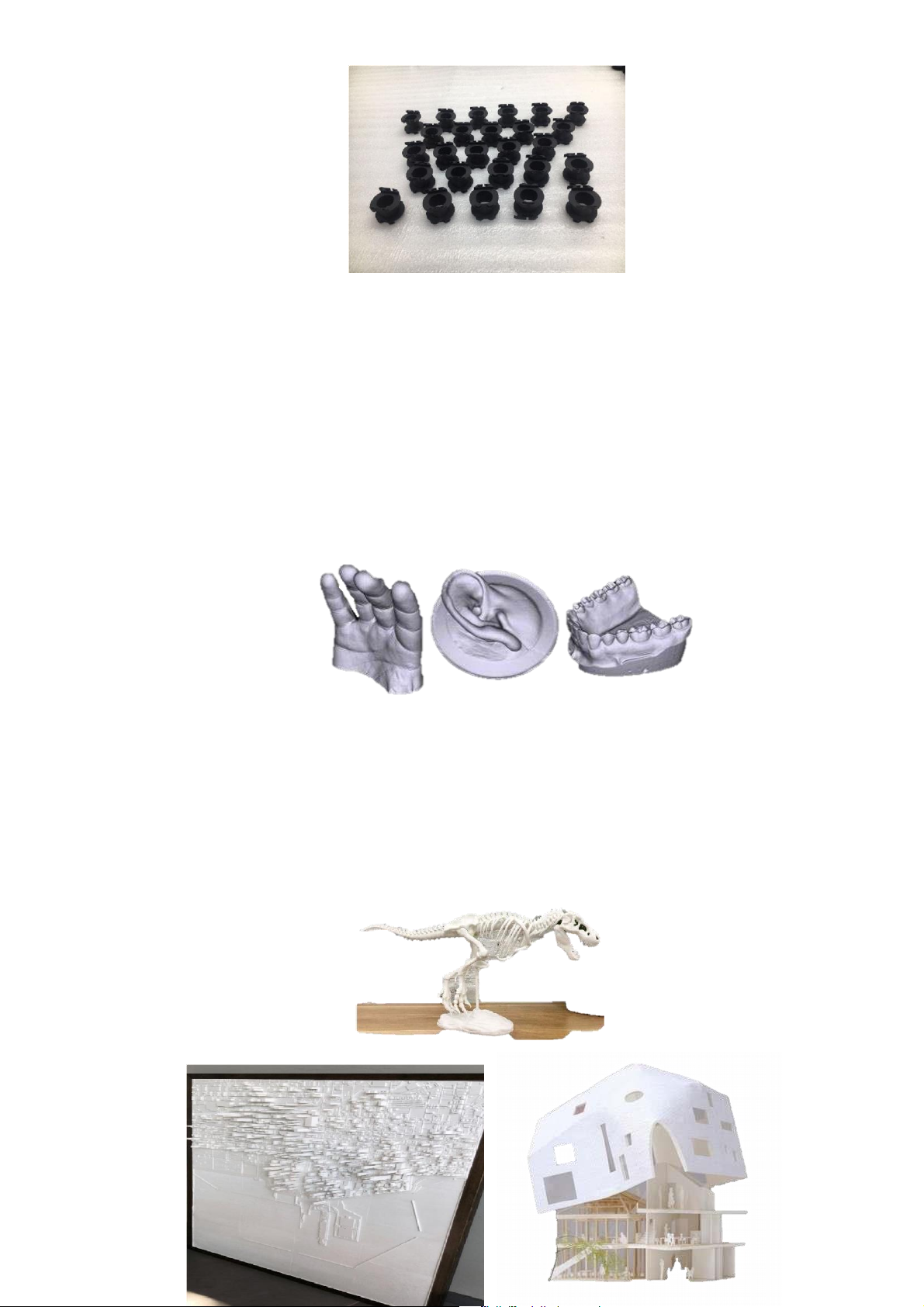
Manufacturing: 3D scanners are widely used in the manufacturing industry to
capture the precise dimensions of objects and components for product design, quality control, and inspection. lOMoARcPSD|36625228
Fig 1.7: 3D scanning technology and applications in the manufacturing industry
Architecture and construction: 3D scanners are used in architecture and
construction to capture accurate measurements and create 3D models of buildings,
infrastructure, and other structures.
Fig 1.8: In the construction industry
Healthcare: 3D scanning is used in healthcare to capture detailed images of internal body
parts for medical procedures, diagnosis, and treatment planning.
Fig 1.9: In the medical industry
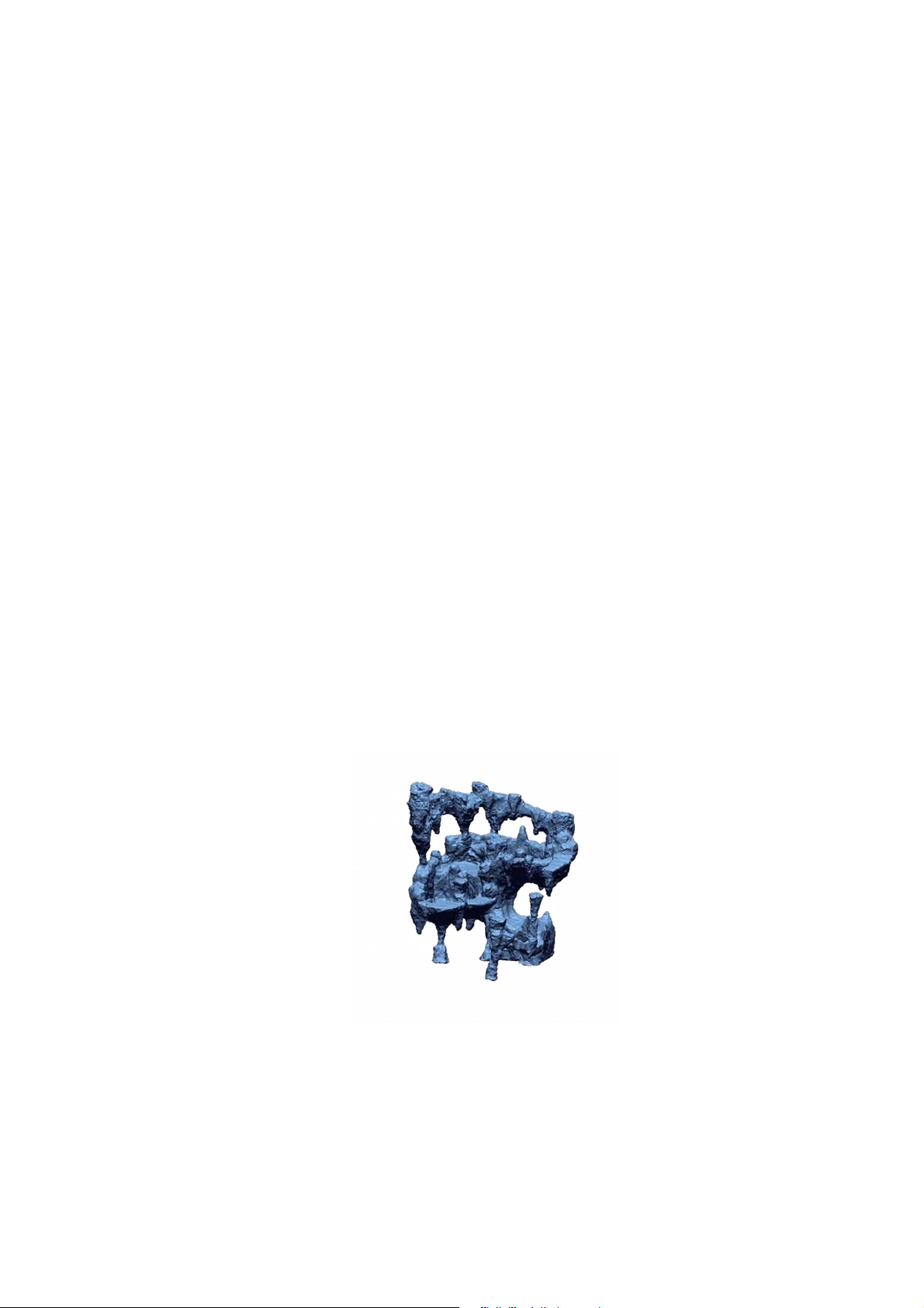
In the museum industry: The biggest purpose of the application for the museum
industry is to store data of related artifacts in a digital format with high accuracy. This
data is used for practical purposes such as research, restoration to ensure the highest originality of artifacts, . . lOMoARcPSD|36625228
Fig 1.10: In the museum industry
In the field of coordinate surveying: Coordinating surveying industry data requires
high accuracy because it is used for many different purposes. 3D scanning technology
helps to scan the parts to be measured with high accuracy as well as full details. The
3D scanning application helps to ensure that the construction, inspection and
monitoring processes are based on a reliable source of measured 3D data.
Fig 1.11: In the field of coordinate surveying
Arts and Entertainment: 3D scanning is increasingly used in the field of
entertainment, such as movie making and video game development, to capture 3D
models of characters, objects, and environments.
Education and research: 3D scanners are used in the field of education and
research to create 3D models of historical artifacts and natural specimens, improving
the preservation and accessibility of these items.
Automotive and Aerospace: 3D scanners are used in the automotive and aerospace
industries to capture precise measurements and create 3D models of parts and
components, for design, testing, and maintenance purposes.
Consumer products: 3D scanners are widely used for customization and
personalization of consumer products, such as footwear, glasses, and other clothing items. lOMoARcPSD|36625228
Overall, 3D scanners have a broad range of applications in various
industries, helping to improve processes, reduce costs, and provide greater accuracy
and efficiency in a variety of fields- from manufacturing to healthcare, research to consumer goods.
1.5. Structure of a 3D scanner machine
The structure of a 3D scanner machine can vary depending on the type of scanner and
its intended application. However, most 3D scanners have the following basic components:
A camera or sensor: This is the primary component of the scanner that captures
data about the object being scanned. Some scanners use a single camera or sensor,
while others use multiple cameras or sensors to capture data from different angles.
Fig 1.12: Optical sensor
A light source: Most 3D scanners use a light source to illuminate the object
being scanned, allowing the camera or sensor to capture more accurate data. The type
of light source used can vary, with some scanners using lasers, structured light patterns, or even natural light.
A positioning system: To capture accurate data, most 3D scanners need to
precisely position the object being scanned and the camera or sensor. This positioning
system can be built into the scanner itself or can be an external component. lOMoARcPSD|36625228
Data processing software: Once the scanner has captured data about the
object, it needs to be processed by specialized software to create a 3D model. This
software can be included with the scanner or can be purchased separately.
Display and interface: Many 3D scanners have a built-in display that allows the
user to see the scanned data in real time. They also have user-friendly interfaces that
allow users to adjust settings and customize the scanning process.
Overall, the components of a 3D scanner work together to capture precise data about an
object and create a 3D model that can be used in a variety of applications.
1.6. Working principle of scan3D machine:
The working principle of a 3D scanning machine is to capture information about an
object and create a comprehensive 3D model of it. This process involves the following steps:
Object preparation: First, the object must be prepared for scanning. The object
needs to be placed on a calibrated and precisely controlled background.
Scanning the object: Once the object is prepared, the 3D scanning machine will
use its light source and camera or sensors to scan the object from multiple angles,
capturing the data points to create a 3D point cloud.
Data processing: The 3D point cloud information is imported into data
processing software to create a 3D model of the object. The software uses algorithms
to create a detailed 3D model with dimensional information, shape, and smaller details.
Create a 3D model: The point cloud data is used to create an accurate 3D model
of the object. This 3D model can be exported to file formats such as STL, OBJ or PLY
and can be used for 3D printing or for other applications such as simulation and design.
In summary, the working principle of a 3D scanning machine is to collect data points
about an object from multiple angles, process that data and create an accurately
detailed 3D model of the object. This process provides dimensional information, shape,
and detail of the object for use in various applications.
1.7. Technical requirements of a 3D scanner machine
There are several technical requirements that a 3D scanner machine should meet to ensure
its efficient and accurate performance. Some of these requirements include: lOMoARcPSD|36625228
High Accuracy: A 3D scanner machine must have high accuracy to detect
small details in an object and provide accurate measurements in the 3D model. The
accuracy of 3D scanning machine should be below 0.1mm for detailed scans.
High Resolution: The 3D scanner machine must have high resolution sensors or
cameras to capture high-quality images of the object being scanned. The resolution
should be at least 640 x 480 or better for capturing fine details.
High Speed: The 3D scanner machine should have a high scanning speed to
reduce the time taken to scan an object. A high-speed scanner can capture more data
points in less time. Scan3D machine should be capable of scanning at a minimum rate of 30 frames per second.
Automatic Calibration: The 3D scanner machine should feature automatic
calibration to ensure its accuracy and quality of data. Calibration is essential to align
the axis of the sensors and to get the accurate result.
Portability: For ease of use and to increase its usefulness, a 3D scanner machine
should be compact and portable to carry it around from one location to another.
User-friendly software: The software used to process the data, such as 3D
model creation, should be simple to use with a user-friendly interface to help make the process simpler and faster.
Compatibility: The 3D scanner machine should be compatible with different
operating systems to ensure universal use and easy transferring of files to different devices.
In conclusion, a 3D scanner machine should have high accuracy, high resolution, high
speed, automatic calibration portability, user-friendly software, and compatibility to
ensure efficient, accurate, timely, and mobile 3D scanning operations.
1.8. Maintenance instructions of Scan 3D machine
To ensure the stable operation and longevity of a 3D scanner machine, it is vital to
follow the manufacturer's maintenance instructions and recommendations. Below are
some general guidelines for the maintenance of the 3D scanner machine: lOMoARcPSD|36625228
Regular cleaning of the machine: The scanner should be cleaned
frequently to remove any dust, debris, or fingerprints. The lens surface and camera
parts should be carefully cleaned and maintained to avoid any contamination or damage.
Ensure proper storage and transportation: The scanner should be stored in its
original packaging or a suitable protective case when not in use or during
transportation. Avoid exposing the scanner to extreme temperature or humidity
changes, as this can lead to damage or inaccurate results.
Calibrate the scanner: Regular calibration of the scanner is necessary to ensure
accurate and consistent results. Calibration can be performed using calibration targets
or software provided by the manufacturer. Follow the instructions from the
manufacturer for calibration and software updates.
Check for firmware and software updates: Regularly check for any available
firmware or software updates provided by the manufacturer to ensure the scanner is
upto-date and to maintain its optimal performance.
Check for wear and tear: Regularly inspect the scanner for signs of wear and
tear such as cracks, dents, or scratches on the exterior or lens surface. These types of
damage to the scanner can affect the accuracy and result in a loss of data.
Avoid physical damage: The scanner should be protected from physical damage
and impacts. Avoid dropping or knocking the scanner, which may cause irreversible
damage to the internal and external components.
By following these maintenance guidelines, the 3D scanner machine can last for many
years while maintaining its accuracy and performance. lOMoARcPSD|36625228
CHAPTER 2: COORDINATE MEASURING MACHINE (CMM)
2.1. Coordinate Measuring Machine concept
A coordinate Measuring Machine (CMM) is an advanced and versatile measuring
device. It is a device that can measure the geometric characteristics of objects with
high accuracy, including three-dimensional coordinates, surface profiles, and other critical part features.
The CMM concept relies on a position sensor to measure X, Y, and Z coordinates
for specific parts of an object, enabling the creation of a 3D model. Typically, a CMM
can use contact or non-contact measurement methods such as laser sensors or machine vision to obtain the 3D model.
Fig 2.1: Coordinate Measuring Machine (CMM)
CMM machines are commonly used in quality control processes to measure
dimensions such as length, width, sample measurement, angle measurement, direction,
or depth. Additionally, the machines provide convenience for the sampling or shaping stages during production.
By applying 3D measuring machines, not only can the accuracy of parts or final
products be improved, but the inspection process can also be shortened, thus increasing
productivity and output for the factory while ensuring the product's quality.
2.2. Advantages & Disadvantages of Coordinate Measuring Machine Advantages of CMM:
• High Precision: CMM provides accurate measurement data, making it the best
measurement tool for highly precise objects. lOMoARcPSD|36625228
• Time-Saving: With automatic measurement and scanning features, CMM
speeds up the inspection process, reducing the time required to check parts manually.
• Accuracy: The computerized nature of CMM reduces the possibility of human
error, ensuring measurement accuracy.
• Customization: CMM can be customized to meet specific measurement needs,
offering flexibility in measurement applications.
• Data Analysis: CMM generates data in a format that is easy to understand and
analyze, helping to identify any issues in the manufacturing process. Disadvantages of CMM:
• High Cost: The cost of a CMM machine can be high, which may be difficult for
small or medium-sized businesses to afford.
• Maintenance: CMM requires regular maintenance to ensure proper operation
and to keep it in optimal condition.
• Complexity: CMM is a complex machine and may require specialized training for operators and programmers.
• Environmental Limitations: CMM may be affected by environmental factors
such as temperature, humidity, and vibrations, which may affect measurement accuracy.
• Size Limitations: CMM size limitations may restrict its ability to measure larger
parts, and multiple CMMs may be needed to inspect larger objects.
Overall, CMM is a highly accurate measurement tool that saves time, provides
data analysis, and improves manufacturing processes. However, the cost, maintenance,
and environmental limitations may make it less suitable for all manufacturing
2.3. Classification of Coordinate Measuring Machines (CMM).
CMMs are classified based on various criteria, including structure, measurement
method, size, and accuracy. Here are some main classifications: According to the structure: Bridge CMM:
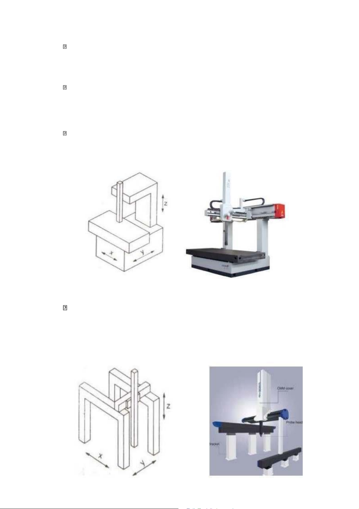
A bridge CMM (Coordinate Measuring Machine) is a type of three-dimensional
measuring device that uses a bridge-like structure to support the horizontal arm and
probe that moves along the surface of the workpiece. The term "bridge" comes from lOMoARcPSD|36625228
the design of the CMM, which consists of a horizontal arm that moves along the Xaxis,
a vertical column that moves along the Z-axis, and a bridge-like structure that connects
the two, allowing for movement along the Y-axis.
The bridge CMM is commonly used in manufacturing industries where precise
measurements are required, such as aerospace, automotive, and medical device
manufacturing. It uses a combination of mechanical, electronic, and software systems
to accurately measure the dimensions and features of an object. The structure is
typically made from a high-rigidity material, such as granite, to ensure stability and accuracy during measurement.
The bridge CMM works by moving the probe along the surface of the workpiece,
while the sensors attached to the arm detect its position and orientation. This
information is then processed by the software to create a 3D model of the object being measured.
Compared to other types of CMMs, the bridge CMM typically has a larger
measuring range, making it suitable for measuring larger parts or assemblies. However,
it can be limited by its size, as the size of the workpiece being measured must fit
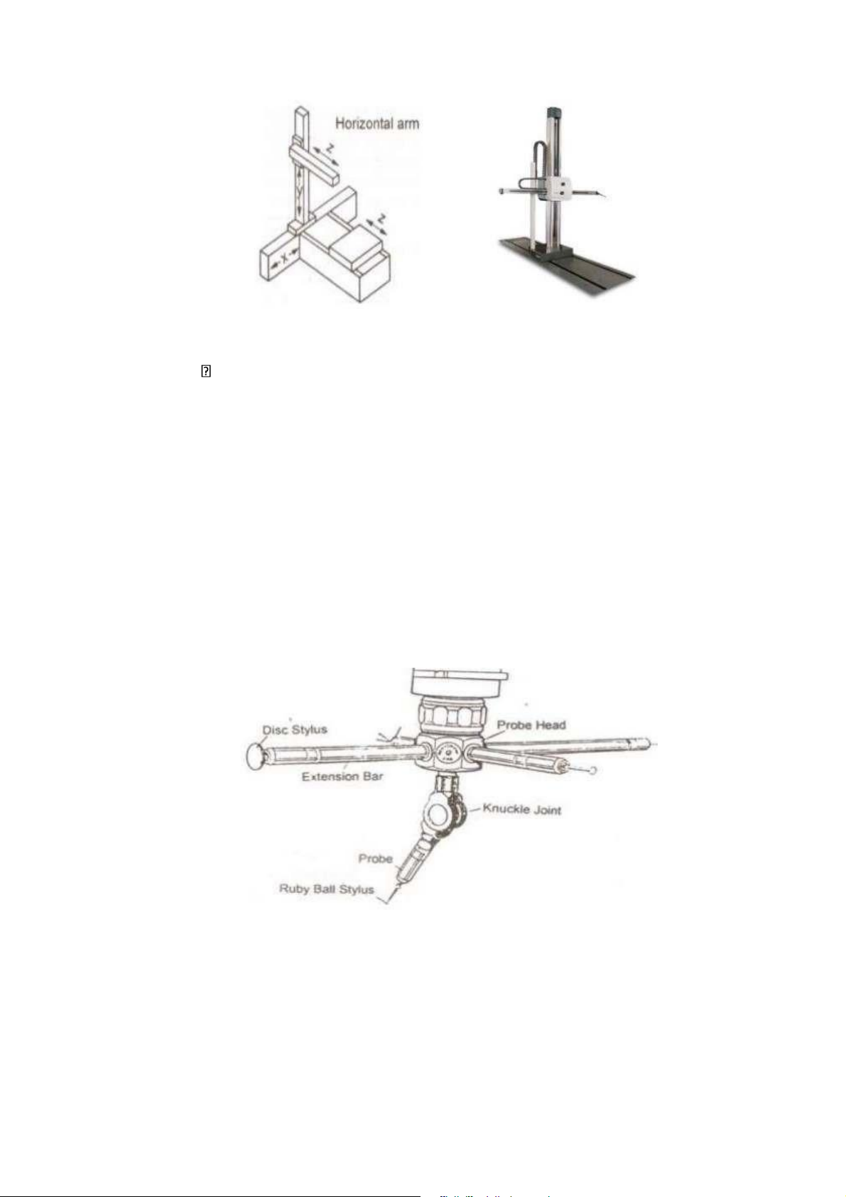
within the available measurement volume. Horizontal arm CMM:
A horizontal arm CMM (Coordinate Measuring Machine) is a type of
3dimensional measuring device that uses a horizontal arm to move the probe around
the surface of a workpiece. It uses a combination of mechanical, electronic, and
software systems to accurately measure the dimensions and features of an object.
The horizontal arm CMM typically consists of a granite surface plate, a horizontal
arm that can move along the X and Y axes, a vertical column that moves along the Z
axis, and a probe that is attached to the end of the arm. The arm contains a number of
sensors that measure its position, orientation, and movement, and this information is
processed by the software to generate a 3D model of the object being measured.
The horizontal arm CMM is widely used in manufacturing industries where precise
measurements are required, such as aerospace, automotive, and medical device
manufacturing. It is capable of measuring complex geometries and can be used to
inspect everything from small parts to large assemblies. lOMoARcPSD|36625228
Fig 2.2:: Horizontal Type CMM Rotary table CMM:
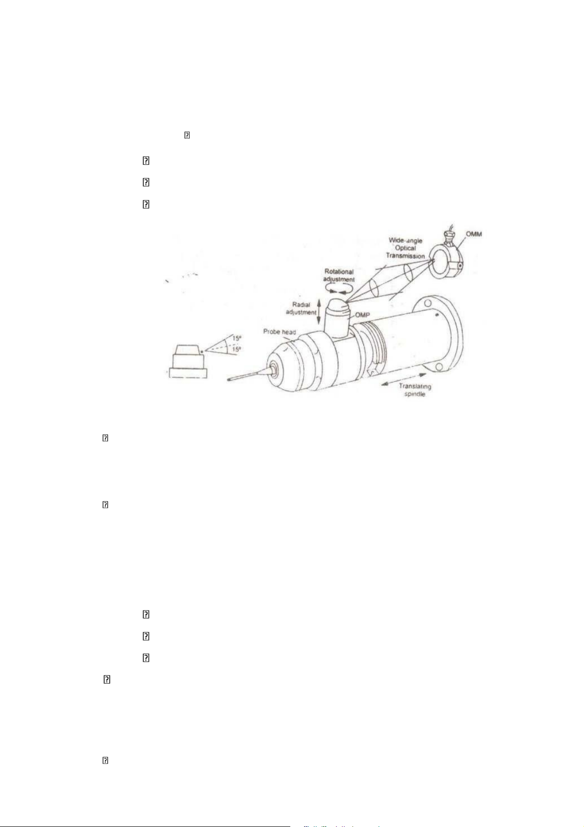
A rotary table CMM (Coordinate Measuring Machine) is a type of CMM that uses
a rotary table to support and rotate the workpiece being measured. The rotary table is
typically mounted on the CMM's measuring platform, and is used to position the
workpiece at different angles for measurement.
This type of CMM is often used in industries such as aerospace and automotive
manufacturing, where complex geometries are common and measurements must be
taken at multiple angles. The rotary table allows for measurements to be taken at
almost any angle, which makes it highly versatile.
Fig 2.3:: Multiple stylus Probe Head
The rotary table CMM typically consists of a measuring platform, a support
structure for the rotary table, a probe system, and software for data analysis. The probe
system is used to collect data points on the workpiece surface, which are then
processed by the software to create a 3D model of the part being measured. lOMoARcPSD|36625228
One advantage of the rotary table CMM is its ability to measure features on
cylindrical or spherical surfaces, which are difficult or impossible to measure with
other types of CMMs. Another advantage is the ability to measure multiple features on
a workpiece without the need to reposition it. This improves efficiency and reduces measurement time.
The rotary table CMM is available in various sizes and accuracy levels to meet
different measurement requirements. It is commonly used in conjunction with other
metrology equipment, such as laser scanners, to create a comprehensive measurement system. Portable CMM:
A portable CMM (Coordinate Measuring Machine) is a type of CMM that is
designed to be easily transported to different locations and set up for measuring tasks.
It is typically smaller and lighter than traditional stationary CMMs, allowing it to be
used in areas where space is limited or where it is not feasible to move the parts to a stationary CMM.
Portable CMMs usually consist of a handheld probe, a tracking device, and
software for data analysis. The tracking device may use a variety of technologies, such
as cameras or lasers, to create a coordinate system for the probe. The handheld probe is
used to touch the part being measured at various points, collecting geometric data that
is processed by the software to create a 3D model.
One advantage of portable CMMs is their flexibility in measuring large or complex
parts that cannot be moved or require precise measurements in situ. They are also
useful for measurement tasks in the field or for managing quality inspections in
production runs where the parts need to be checked at different stages of production.
Portable CMMs are available in different sizes and accuracy levels to meet varying
measurement needs. They are commonly used in industries such as aerospace,
automotive, and shipbuilding, where parts are often large and require accurate measurements in situ.
According to the measurement method: Optical CMM: lOMoARcPSD|36625228
An optical CMM (Coordinate Measuring Machine) is a type of CMM that uses
optical sensors to measure the dimensions and features of a part. The sensors capture
data by analyzing the light reflected off the surface of the part being measured.
There are different types of optical sensors used in optical CMMs, including white
light sensors, confocal sensors, and laser sensors. White light sensors use a technique
called fringe projection to gather data, while confocal sensors use a pinhole aperture to
capture data from a specific depth of the part surface. Laser sensors, on the other hand,
use a laser beam to measure distances between the sensor and the part surface.
One advantage of optical CMMs is their ability to measure parts that are difficult
to measure with touch probes, such as soft, flexible, or delicate parts. Optical CMMs
can also measure features that are difficult to access or have complex shapes. The
noncontact measuring technique of optical CMMs prevents damage to the parts being measured.
Optical CMMs are utilized in various industries, including the aerospace,
automotive, and medical industries, to measure critical components with high accuracy.
They are also used in research and development to prototype new designs and test functionality.
Software is used to process the data collected by the optical sensors, creating a 3D
model of the part being measured. Optical CMMs are available in various sizes and
with different levels of accuracy, enabling them to perform measurements with a high degree of precision. Touch trigger CMM:
A touch trigger CMM (Coordinate Measuring Machine), also known as a tactile
CMM, is a type of CMM that uses a touch probe to collect data points on the surface
of a part being measured. The touch probe is a precision instrument that is mounted on
the measuring platform of the CMM.
When the touch probe makes contact with the surface of the part, it sends a signal
to the CMM, which records the X, Y, and Z coordinates of the point of contact. These
points are collected incrementally, creating a cloud of data points that can be processed
by software to create a 3D model of the part being measured. lOMoARcPSD|36625228
Touch trigger CMMs are ideal for measuring parts with geometric features that
require precise physical contact to be measured accurately, such as holes, slots, and
rounded edges. They are also useful for measuring parts with surface texture and roughness.
One advantage of touch-trigger CMMs is their capability to measure parts of
varying size and complexity. They can be used for small, precision components or
large parts that require several measurements to be taken. Touch trigger CMMs are
also highly accurate and provide repeatable measurements.
Touch trigger CMMs typically come with software that allows for data analysis
and provides real-time feedback on the measurement process. They are widely used in
manufacturing, aerospace, and automotive industries to ensure precise component dimensions. Laser CMM:
A laser CMM (Coordinate Measuring Machine) is a type of CMM that uses laser
sensors to generate a 3D model of the part being measured. The laser sensors are
mounted on the measuring platform of the CMM and are used to scan the surface of the part.
Laser CMMs can be used to measure a wide range of parts, including small,
complex components and large, bulky objects. They are capable of acquiring large
volumes of data very quickly and can be used to measure parts with difficult-to-reach
features, such as deep holes or grooves.
There are different types of laser sensors used in laser CMMs, including structured
light sensors, time-of-flight sensors, and triangulation sensors. Structured light sensors
project a pattern of light onto the surface of the part, which is captured by a camera to
generate a 3D image. Time-of-flight sensors use pulses of laser light to measure the
distance between the sensor and the part. Triangulation sensors use laser light to create
a line of light on the part surface, which is captured by a camera to generate a 3D image.
One advantage of laser CMMs is their accuracy. Laser sensors are capable of
measuring to extremely high levels of precision, making them well-suited for use in lOMoARcPSD|36625228
quality control applications. They are also fast and efficient, allowing for rapid
measurement and analysis of parts.
Laser CMMs often come equipped with software that provides real-time data
analysis, allowing users to quickly and easily generate reports from the collected data.
They are commonly used in manufacturing, aerospace, and automotive industries, as
well as in research and development applications. Radio frequency CMM:
A radio frequency (RF) CMM (Coordinate Measuring Machine) is a type of CMM
that uses radio waves to measure the distance between the probe and the part being
measured. The RF CMM uses a probe with a small antenna that emits a radio wave.
The wave travels from the antenna to the part being measured, where it is reflected
back to the antenna. The CMM then calculates the distance between the probe and the
part based on the time it took for the wave to travel to the part and back to the antenna.
RF CMMs are particularly useful for measuring parts that are electrically
conductive or that have metallic coatings. They can also be used for parts that are
difficult to reach using other types of probes, such as deep holes or narrow channels.
One advantage of RF CMMs is their accuracy. They are capable of measuring to
extremely high levels of precision, making them well-suited for use in quality control
applications. They are also fast and efficient, allowing for rapid measurement and analysis of parts.
RF CMMs are commonly used in manufacturing, particularly in the electronics
industry, where they are used to measure printed circuit board (PCB) assemblies and
other electronic components. They are also used in the aerospace and automotive
industries for quality control and inspection of precision components. RF CMMs are
often used in combination with other types of CMMs, such as touch triggers and laser
CMMs, to provide comprehensive measurement data.
According to the size small-sized CMM machine:
Small-sized CMM machines are compact measuring systems that are designed for
measuring small, precision components. These machines typically have a small lOMoARcPSD|36625228
measuring range of several centimeters and are commonly used for measuring medical
implants, watches, computer components, and other small machined parts.
Small-sized CMM machines are ideal for use in research and development
laboratories, where precision measurements are required to evaluate the performance
of new products or prototypes. They are also used in quality control applications,
where rapid measurement and analysis of small components are required.
One advantage of these machines is their compact size, which makes them easy to
fit into small workspaces and reduces the overall footprint of a laboratory or
manufacturing facility. They are also lightweight and portable, which makes them easy to move around as needed.
Small-sized CMM machines may use a variety of measurement technologies,
including touch trigger probes, laser sensors, and optical sensors. These machines are
often equipped with advanced software that provides real-time data analysis, allowing
operators to quickly identify issues or trends in the production process.
While small-sized CMM machines are not suitable for measuring large or complex
parts, they are highly accurate and repeatable, making them an important tool for
precision manufacturing and quality control applications. They are commonly used in
industries such as medical device manufacturing, watchmaking, and electronics. Standard CMM machine:
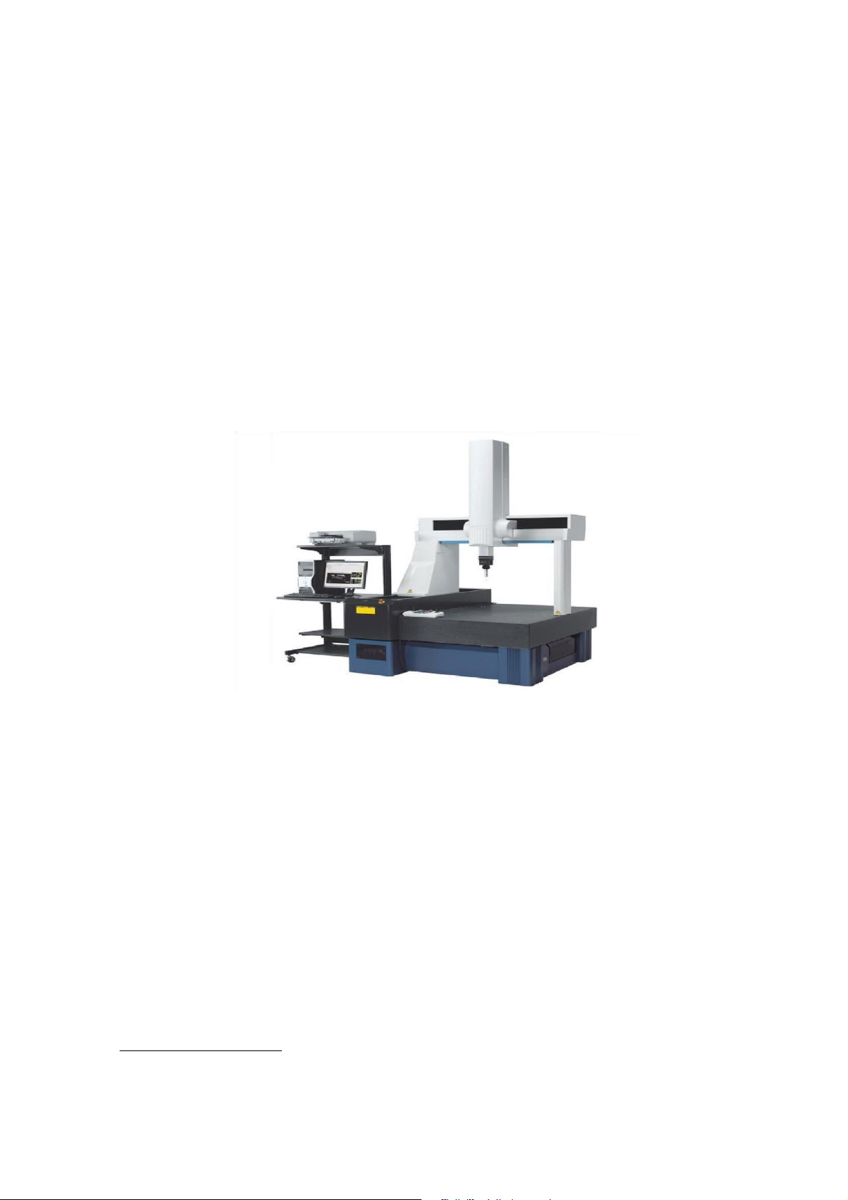
A standard CMM (coordinate measuring machine) is a measuring system that is
used to measure the size, shape, and position of a part in three-dimensional (3D) space.
It is commonly used in manufacturing facilities, research and development labs, and
quality control laboratories to measure the accuracy and precision of parts and components.
A standard CMM typically consists of a granite or aluminum table, a vertical
column, and a horizontal arm that suspends a probe over the part being measured. The
machine moves the probe in the X, Y, and Z directions to measure the part's geometry
by touching the part's surface or by using non-contact measurement sensors such as lasers or cameras. lOMoARcPSD|36625228
Standard CMM machines employ different types of probes, including touchtrigger
probes, scanning probes, and optical probes. The touch-trigger probe senses the point
of contact with the surface of the part and records the XYZ coordinates. The scanning
probe provides an array of measurement data points over a surface area by scanning
the probe's contact over the workpiece. Optical probes use a non-contact method of
imaging the surface of a workpiece and analyzing the resultant image to obtain precise measurements.
Standard CMMs provide high levels of accuracy and repeatability and can measure
parts with dimensions ranging from small components to large assemblies. They are
commonly used in industries such as aerospace, automotive, medical, and
manufacturing, where precision measurement is essential to verify the quality and
functionality of parts and components.
The data collected by a CMM machine is analyzed by software that generates
reports and allows for visual representation of measurement results. The data can be
used for statistical process control (SPC), process improvement, and root cause analysis of quality issues. Large CMM machine:
A large CMM (coordinate measuring machine) is a measuring system that is used
to measure the size, shape, and position of large parts or assemblies. It is commonly
used in industries such as aerospace, defense, transportation, and energy, where large
components need to be measured accurately.
Large CMM machines are typically designed with a bed, which can measure parts
with a range of 5-6 meters in length, vertical columns that extend above the bed to
support the horizontal arm carrying the probe, and a bridge gantry or horizontal arm
that extends over the part being measured. Large CMM also typically housed in
temperature controlled enclosures.
Large CMM machines are capable of measuring complex geometries with high
precision, which makes them ideal for use in quality control or inspection applications.
They use a variety of probes, including contact probes, scanning probes, and
noncontact probes such as laser sensors and optical sensors. The type of probe used lOMoARcPSD|36625228
will depend on the complexity of the part being measured and the type of measurement required.
Large CMM machines are often equipped with advanced software that allows for
real-time data analysis. They automatically generate 3D models, inspection reports,
and measurement data analysis. These capabilities greatly simplify workflow and
lower inspection time by reducing the need for time-consuming manual work.
Applications for large CMM machines include aircraft or spacecraft components,
wind turbine blades, Automotive assembly, railroad components, and large industrial
equipment. The data generated by a large CMM machine can be used for process
improvements, quality data analysis, and root cause analysis of quality issues. According to the accuracy:
Low-accuracy CMM machine (under 10 µm):
A low-accuracy CMM (coordinate measuring machine) is a measuring system that
provides basic measurements of small- to mid-sized parts. They are designed for
applications that do not require highly precise measurements and are typically less
expensive than high-accuracy CMM machines.
Low-accuracy CMM machines have a measuring range of several centimeters to a
few meters and can measure simple geometries such as circles or straight lines. They
are generally equipped with a single-touch trigger probe or a scanning probe to provide
part coordinates and dimensions. Measurement accuracy on these types of machines
can range from around 20 to 500 micrometers.
Low-accuracy CMM machines are commonly used in quality control processes,
such as quick inspection of small parts, process control checks, and initial verification
of new products or prototypes. They may also be used in machine shops or small-scale
production facilities, where accuracy is less critical or when the parts being measured
do not require tight tolerances.
One advantage of low-accuracy CMM machines is that they are relatively easy to
use and require minimal training to operate. They are also more affordable than
highaccuracy CMM machines, making them a more cost-effective option for smaller organizations. lOMoARcPSD|36625228
However, the limitations of these machines are their inability to measure complex
geometry at high accuracy or their inability to perform as required if the target
material's surface quality is poor. Their applications are also limited to small- to
midsized components, some features cannot be measured, and as a result, the data
output will not support complex statistical process control.
Medium-accuracy CMM machine (from 5 to 1 µm)
A medium-accuracy CMM (coordinate measuring machine) is a measuring system
that provides higher precision measurements than low-accuracy CMMs, but not as
precise as high-accuracy CMMs. Medium-accuracy CMMs are designed for
applications that require more precise measurements than what can be achieved with
low-accuracy CMMs but do not require the highest level of accuracy.
Medium-accuracy CMMs have a measuring range of several centimeters to a meter
or more, and can measure complex geometries with greater accuracy and detail. These
machines may use a range of probes, such as a touch-trigger probe or scanning probe,
depending on the application. Measurement accuracy on medium-accuracy CMM
machines can range from around 10 to 100 micrometers.
Medium-accuracy CMMs are used in a variety of industries, such as aerospace,
automotive, electronics, and medical devices, where precision is important but not
critical. They are also commonly used in quality control processes, such as in
midvolume manufacturing facilities and machine shops.
One advantage of medium-accuracy CMM machines is that they provide higher
accuracy measurements than low-accuracy CMMs, while still being relatively
affordable compared to high-accuracy CMMs. Additionally, they offer greater
flexibility in terms of the size and complexity of parts that can be measured compared to low-accuracy CMMs.
However, limitations of medium-accuracy CMM machines include their inability
to perform at the highest levels of accuracy required for certain applications, as well as
their inability to measure extremely small or delicate parts with full accuracy. Proper
calibration and maintenance are important to maintain the accuracy of mediumaccuracy CMM machines.
High-accuracy CMM machine (under 1 µm) lOMoARcPSD|36625228
A high-accuracy CMM (coordinate measuring machine) is a measuring system that
provides the highest level of precision measurements with an accuracy below 5 µm.
These machines are designed for applications that require extremely precise
measurements, where even the smallest deviation can result in significant quality issues or safety concerns.
High-accuracy CMMs have a measuring range of several centimeters to several
meters and can measure complex geometries with the highest level of precision and
detail. These machines may use a variety of probes, such as tactile probing systems,
scanning probes, and non-contact optical probes, depending on the specific application and measurement requirements.
One of the primary advantages of high-accuracy CMM machines is their ability to
measure with the highest level of accuracy and repeatability, providing unmatched
precision in the measurement of parts and products. This makes them essential for
industries such as aerospace, medical devices, automotive, and other applications
where the highest standards for quality and safety must be met.
One of the key factors that make high-accuracy CMMs unique is their use of
highly advanced technology, including precision components, advanced software, and
algorithms that enable them to achieve unmatched levels of accuracy and precision,
typically with an accuracy below 1 µm. However, this level of precision comes with a
higher price tag compared to lower-accuracy CMMs.
In addition, high-accuracy CMMs require highly specialized personnel to operate
and maintain the machine properly, as well as a controlled environment with low
levels of vibration, temperature, and humidity to reduce potential measurement errors.
Overall, high-accuracy CMMs are essential measuring tools where the highest
levels of precision, accuracy, and repeatability are required, and where the potential
cost of a measurement error could have serious consequences.
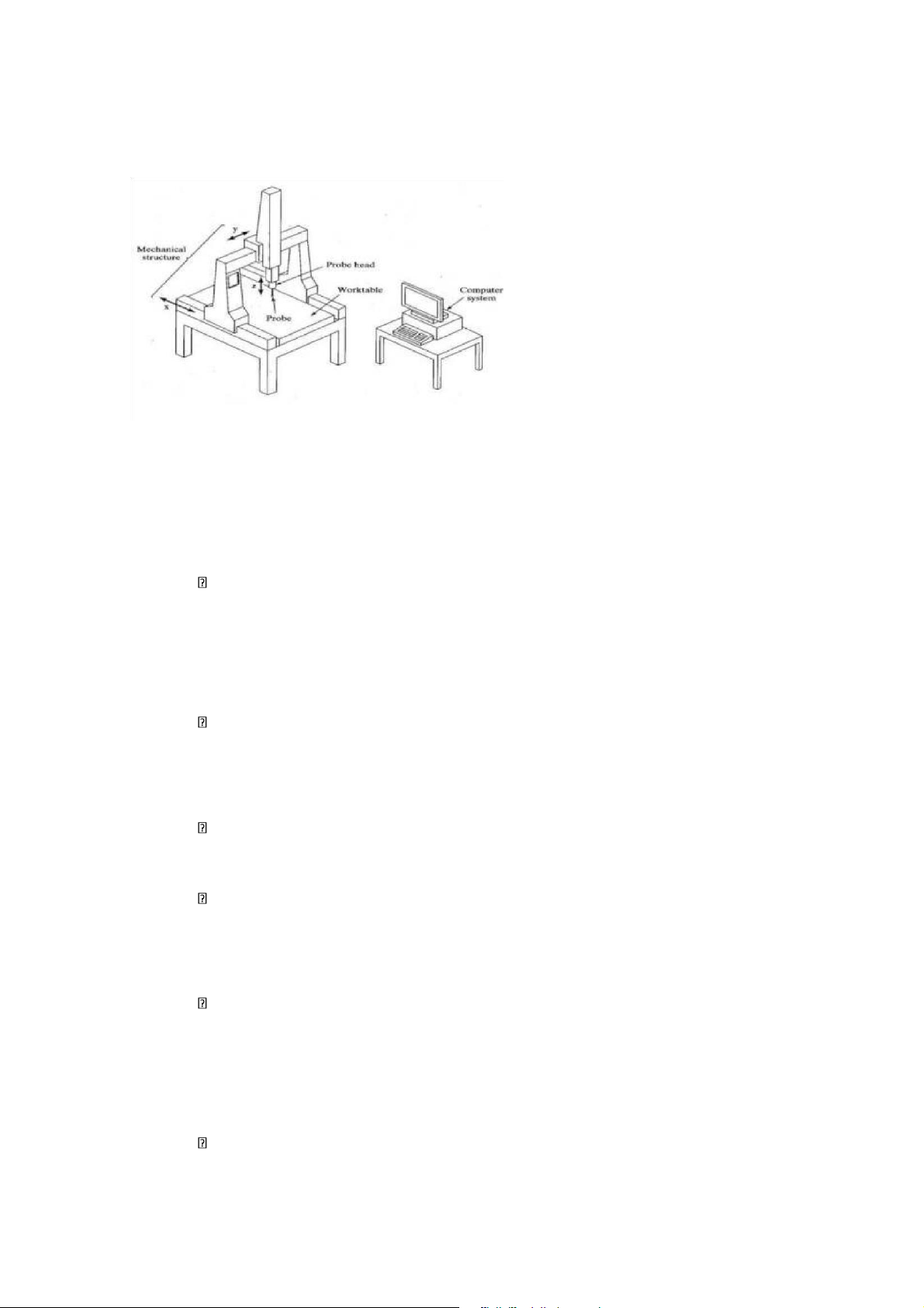
2.4. Structure of Coordinate Measuring Machine
The structure of a Coordinate Measuring Machine (CMM) typically consists of the following components: lOMoARcPSD|36625228
Base: The base is the foundation of the CMM, on which other components of
the machine are mounted. The base is made of a rigid material, like granite or cast iron,
to ensure stability and accuracy.
Bridge: The bridge is a horizontal beam that spans over the measurement area
and moves along the X-axis. The bridge houses the Y-axis drive and measurement systems.
Column: The column is a vertical and stationary structure that provides stability
to the bridge and supports the Z-axis drive and measurement systems. High-end
CMMs may have multiple columns for added stability. Fig 2.4:Column Type CMM
Probe: The probe is the measurement tool that touches the surface Gantryof the
object being measured and records positional data. The probe may be a touch-trigger
probe, a scanning probe, or a non-contact probe, depending on the measurement requirements. lOMoARcPSD|36625228 Fig 2.5:Gantry Type CMM
Common types of probes on a CMM: Touch probe Non-contact probe Optical probe Laser probe
Fig 2.6:Optical transmission Probe
Controller: The controller is the brain of the CMM that manages machine
movements and measurements. It takes input from the software and translates it into
the physical movements of the machine.
Software: The software is the user interface that allows the operator to set up
measurement routines, collect data, and analyze results. The software may also provide
advanced functions like CAD comparison and reverse engineering.
Some popular data Horizontal processing software for CMM machines include: Metrology software CAD software
Statistical Process Control (SPC) software
Drive system: The CMM uses precision motors and positioning devices to move
the probe in three-dimensional space. The X-axis and Y-axis are typically driven by
linear motors, while the Z-axis is driven by a precision ball screw.
Air bearings: High-end CMMs may use air bearings to float the machine on a
cushion of air, reducing friction and enabling smooth and precise movements. lOMoARcPSD|36625228
Overall, the structure of a CMM is designed to provide high levels of accuracy,
precision, and repeatability in the three-dimensional measurement of objects. The
various components of the machine work together to ensure that the measurements are
reliable and repeatable, even over extended.
2.5. Uses of Coordinate Measuring Machines (CMM).
CMMs are commonly used for dimensional measurement, specimen testing, angle,
direction, or depth plots, and duplicating or forming measurements. With the function
of measuring 3-dimensional coordinates X, Y, Z with high accuracy CMM helps
people to measure the size of a product in a better way. Making it possible for the
manufactured part to be assembled accurately or for products that require high
accuracy after production, a coordinate measuring machine is manufactured to take care of this job.
With the point station measuring head of the CMM coordinate measuring
machine, it will have the function of detecting coordinates with extremely high
accuracy, helping to measure the details of objects that are easy to change in size such
as rubber, ect, Soft plastics,…….
The CMM machine control system by software makes it possible to move the
coordinates accurately without machine vibration even when measuring manually.
CMM 3-D measuring machine is capable of measuring 3 dimensions of objects
with very high precision resolution. Not only measuring the length of the machine, but
also measuring the cylindrical roundness and concentricity of the bore on the production part.
In addition, the 3-D measuring machine also has the function of creating
dimension drawings of actual products with 3-D (3D) Laser scanners. lOMoARcPSD|36625228
2.6. Working principle of Coordinate Measuring Machines (CMM)
Fig 2.6: CMM Set-Up Start
the CMM machine and set up the necessary measurement parameters. These parameters include:
Type of measurement sensor: CMM machines can use different types of
sensors such as touch probes, optical sensors, or laser sensors. Choosing the
appropriate sensor type for the object being measured is crucial for achieving the highest accuracy.
Measuring speed: The measuring speed is set to adjust the sensor's speed
on the surface of the object being measured. This also affects accuracy and measuring time.
Resolution: The resolution determines the smallest detail of the
measurement data. Typically, the higher the resolution, the better the accuracy.
Rotating speed of the measuring table: The rotating speed of the
measuring table is set to rotate the table during measurement. This also affects measuring time.
Measurement method: CMM machines can use different measurement
methods such as point measurement, line measurement, and surface measurement.
Choosing the appropriate measurement method for the object being measured is crucial.
Coordinate system: CMM machines can use different coordinate systems
such as linear coordinate systems and spherical coordinate systems. Setting the
correct coordinate system is also crucial for ensuring measurement accuracy. lOMoARcPSD|36625228
Place the object to be measured on the measuring table of the CMM and fix its position.
Use the measuring sensors on the CMM machine to measure points on
the object, thereby determining the coordinates of those points relative to the coordinate system.
Use CMM software to compare the measured coordinates with the preset
coordinates of the object, thereby determining measurement errors.
The control software of the CMM machine has the function of collecting
measurement data from the sensors on the machine and calculating measurement
parameters such as coordinates, diameter, curvature, and deviation. To compare
measured coordinates, the software uses data analysis tools to compare measurement
data with a pre-defined 3D model.
The steps to compare measured coordinates on CMM software include:
Setting up a 3D model: Firstly, a 3D model of the object being measured
is created on CAD software or imported from existing CAD files. This model
will be used to compare with measurement data.
Collect measurement data: After setting up the 3D model, measurement
data will be collected by the sensors on the CMM machine.
Process measurement data: The measurement data will be processed and
calculated by the control software to create measurement coordinates and other measurement parameters.
Compare measurement data with 3D model: The measurement data is
compared to the 3D model to determine the accuracy of the measurement data.
The software will calculate the distance between measured coordinates and the
points on the 3D model, then display the comparison results on the screen.
Evaluate the results: Finally, the comparison results are evaluated to
determine the accuracy of the measurement data and provide any necessary adjustments.
Display measurement results and store measurement lOMoARcPSD|36625228
2.7. Application of Coordinate Measuring Machines (CMM)
Currently, CMM is being widely used in many industries, with different and very diverse applications:
Quality control, mapping, and shaping in the production of aircraft and aircraft
Quality control, mapping and shaping in automobile manufacturing
Quality control, mapping and shaping in electronics manufacturing
Quality inspection, mapping and shaping in the energy industry
Quality control, mapping and shaping in medical device manufacturing
Quality control, fitting and shaping in other manufacturing industries
2.8. Maintenance instructions of Coordinate Measuring Machines (CMM)
To ensure the stable operation of a CMM, it is important to follow manufacturer
instructions for regular maintenance and upkeep. Below are some general guidelines for CMM maintenance:
Regular cleaning of the machine: The surface of the CMM should be cleaned
regularly to remove dust and debris. In particular, the moving parts along the X,
Y, and Z axis should be cleaned thoroughly to remove oil and dirt.
Ensure proper temperature and humidity: The CMM should be placed in a room
with appropriate temperature and humidity to avoid affecting accuracy and stability.
Store components and parts carefully: The components and parts of the
machine should be stored in a dry and stable environment to avoid damage or deterioration.
Use a stable power supply: The CMM requires a stable power supply with good
quality to avoid any impact to the machine's operation.
Perform regular maintenance: The parts and components should be checked and
replaced periodically to ensure the stable operation and accuracy of the machine.
Use appropriate accessories and tools: Use specialized accessories and tools
specifically designed for the CMM to avoid damaging the machine and reducing its accuracy. lOMoARcPSD|36625228 REFERENCE MATERIALS.
[1] JOHAN MOBERG (2017) “Scan3D
machine”https://www.divaportal.org/smash/get/diva2:1200549/FULLTEXT01.pdf
[2] M Edl “3D LASER SCANNERS APPLICATIONS”
https://actasimulatio.eu/issues/2018/IV_2018_01_Edl_Mizerak_Trojan.pdf [3] Ferit
Artkin (January 2023) “CMM Machines and Industrial Applications”
https://www.researchgate.net/publication/367438496_CMM_Machines_and_Industria l _Applications [4]
Rohit Raju Nikam (October 2018 - March 2019) “COORDINATE MEASURINGMACHINE (CMM)”
https://www.researchpublish.com/upload/book/COORDINATE%20MEASURING % 20MACHINE-6840.pdf [5]
Weckenmann, A, Estler, T, Peggs, G., McMurtry, D. (2004), “Probing systems
indimensional metrology”, CIRP Annals-Manufacturing Technology, 53 (2), 657-684. [6]
Ali, S.H.R. (2010), “Two-dimensional model of CMM probing system.”
Journal ofAutomation, Mobile Robotics & Intelligent Systems, 4 (2), 3-7. [7]
W. P. van Vliet, P. H. J. Schellekens, “Accuracy Limitations of Fast Mechanical
Probing” Annals of the CIRP 45(1) 483-487 [8]
A. Weckenmann, T. Estler, G. Peggs, D. McMurtry, “Probing Systems in
Dimensional Metrology” Annals of the CIRP
Document Outline
- CHAPTER 1: SCAN 3D MACHINE
- 1.1. The 3D scanning machine concept:
- Fig 1.1: 3D scanning concept
- 1.2. Advantages & Disadvantages of 3D scanners
- 1.3. Popular types of 3D scanning technology
- Fig 1.2: Structured-light 3D scanner
- Fig 1.3: 3D scanning with laser
- Fig 1.4: X-ray 3D scanner
- Fig 1.5: Photogrammetry 3D scanner
- 1.4.Application in the life of 3D Scanners:
- Fig 1.6:3D scanning technology and its application
- Fig 1.8: In the construction industry
- Fig 1.9: In the medical industry
- Fig 1.10: In the museum industry
- Fig 1.11: In the field of coordinate surveying
- 1.5. Structure of a 3D scanner machine
- Fig 1.12: Optical sensor
- 1.7. Technical requirements of a 3D scanner machi
- 1.8. Maintenance instructions of Scan 3D machine
- 2.1. Coordinate Measuring Machine concept
- Fig 2.1: Coordinate Measuring Machine (CMM)
- 2.2. Advantages & Disadvantages of Coordinate Meas
- 2.3. Classification of Coordinate Measuring Machin
- Fig 2.2:: Horizontal Type CMM
- Fig 2.3:: Multiple stylus Probe Head
- 2.4. Structure of Coordinate Measuring Machine
- Fig 2.4:Column Type CMM
- Fig 2.5:Gantry Type CMM
- 2.5. Uses of Coordinate Measuring Machines (CMM).
- 2.6. Working principle of Coordinate Measuring Mac
- 2.7. Application of Coordinate Measuring Machines
- 2.8. Maintenance instructions of Coordinate Measur
- 1.1. The 3D scanning machine concept:
Tài liệu liên quan:
-
Bảng Tra Môn Dung Sai Và Kỹ Thuật Đo | Trường Đại học Sư phạm Kỹ thuật Thành phố Hồ Chí Minh
40 20 -

Giáo trình Dung sai & Kỹ thuật đo | Trường Đại học Sư phạm Kỹ thuật Thành phố Hồ Chí Minh
70 35 -

Dung sai Thước đo góc | Môn Dung sai & Kỹ thuật đo - Đại học Sư phạm Kỹ thuật Thành phố Hồ Chí Minh
140 70 -

Hướng Dẫn Kiểm Tra từ Trang 16 đến 25 | Môn Dung sai & Kỹ thuật đo - Đại học Sư phạm Kỹ thuật Thành phố Hồ Chí Minh
88 44 -

Đáp án Đề thi cuối kỳ năm 2017-2018 | Môn Dung sai & Kỹ thuật đo - Đại học Sư phạm Kỹ thuật Thành phố Hồ Chí Minh
114 57