Tóm Tắt Chương 3 Kết Cấu Thép: Tóm Tắt Lý Thuyết Dầm Hình | Môn Kết cấu bê tông & bê tông cốt thép - Đại học Sư phạm Kỹ thuật Thành phố Hồ Chí Minh
Tóm Tắt Chương 3 Kết Cấu Thép: Tóm Tắt Lý Thuyết Dầm Hình Môn Kết cấu bê tông & bê tông cốt thép. Tài liệu được sưu tầm gồm 26 trang, giúp bạn ôn tập tốt hơn. Mời các bạn đón xem.
Môn: kết cấu bê tông & bê tông cốt thép 10 tài liệu
Trường: Trường Đại học Sư phạm Kỹ thuật Thành phố Hồ Chí Minh 4.4 K tài liệu
Tác giả:
Preview text:
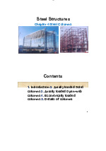
lOMoAR cPSD| 58759230 Steel Structures Chapter 3 Steel beams Contents 1. Introduction 2. Beam section types 3. General dimensions
4. Design of steel floors
5. Design of rolled beams
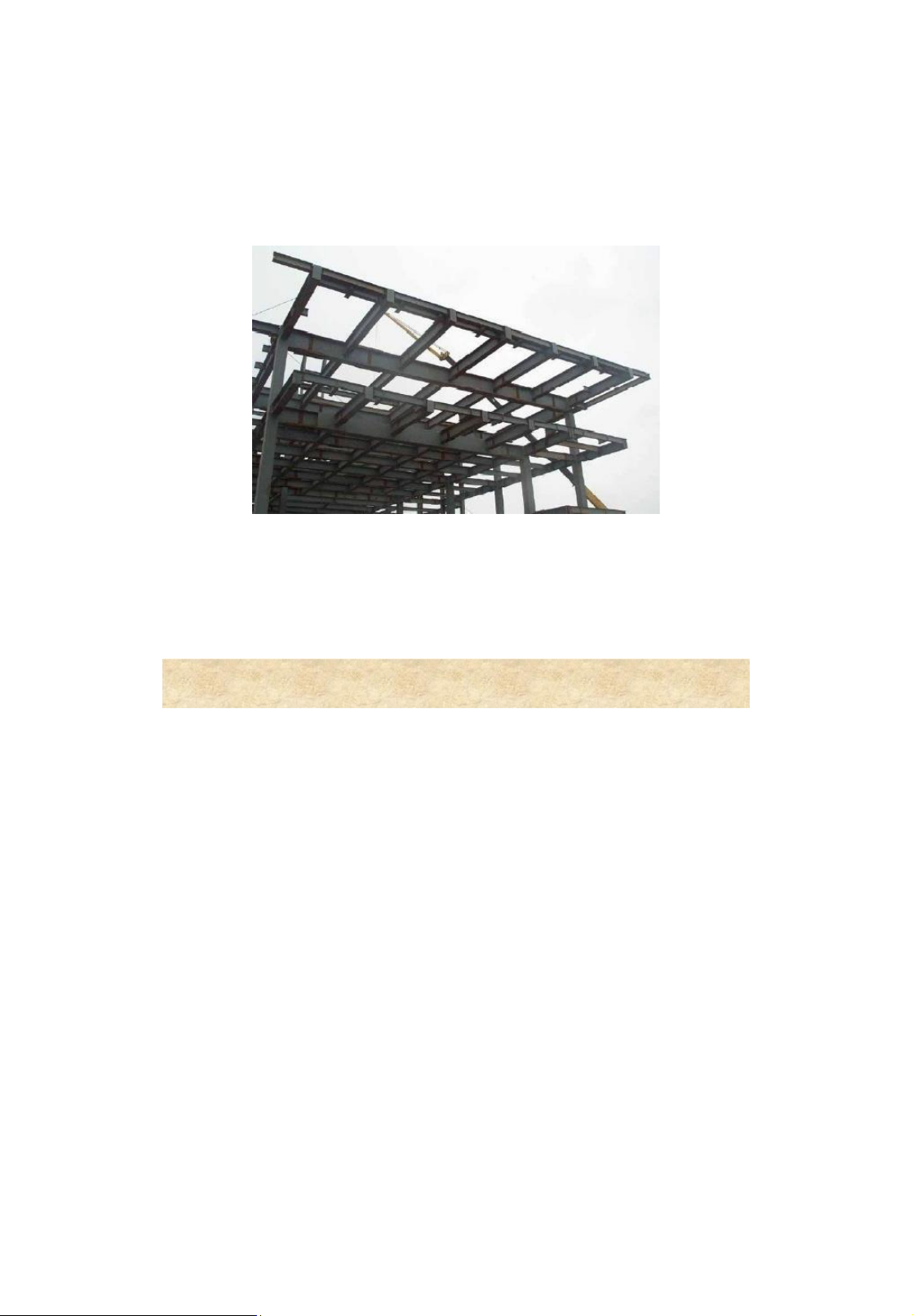
6. Design of built-up beams 7. Worked examples 2 lOMoAR cPSD| 58759230 Introduction
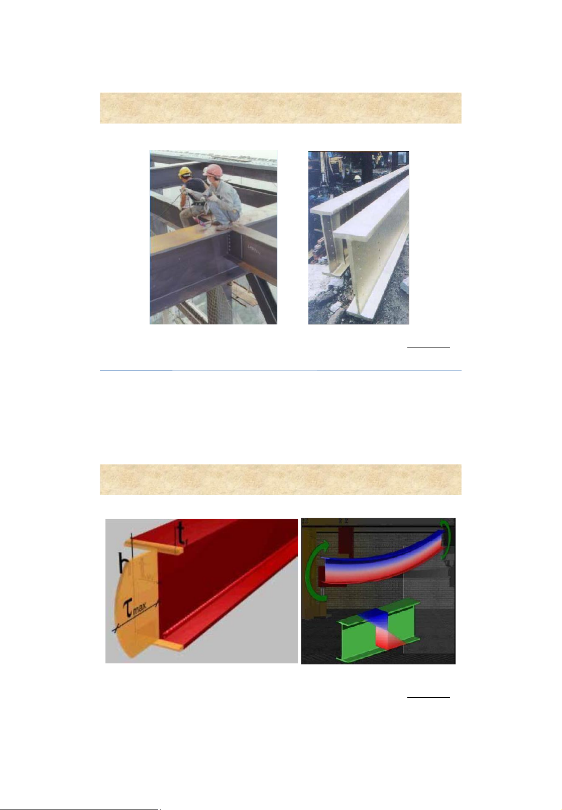
Beams or girders - structural members are subjected to bending 3 Introduction
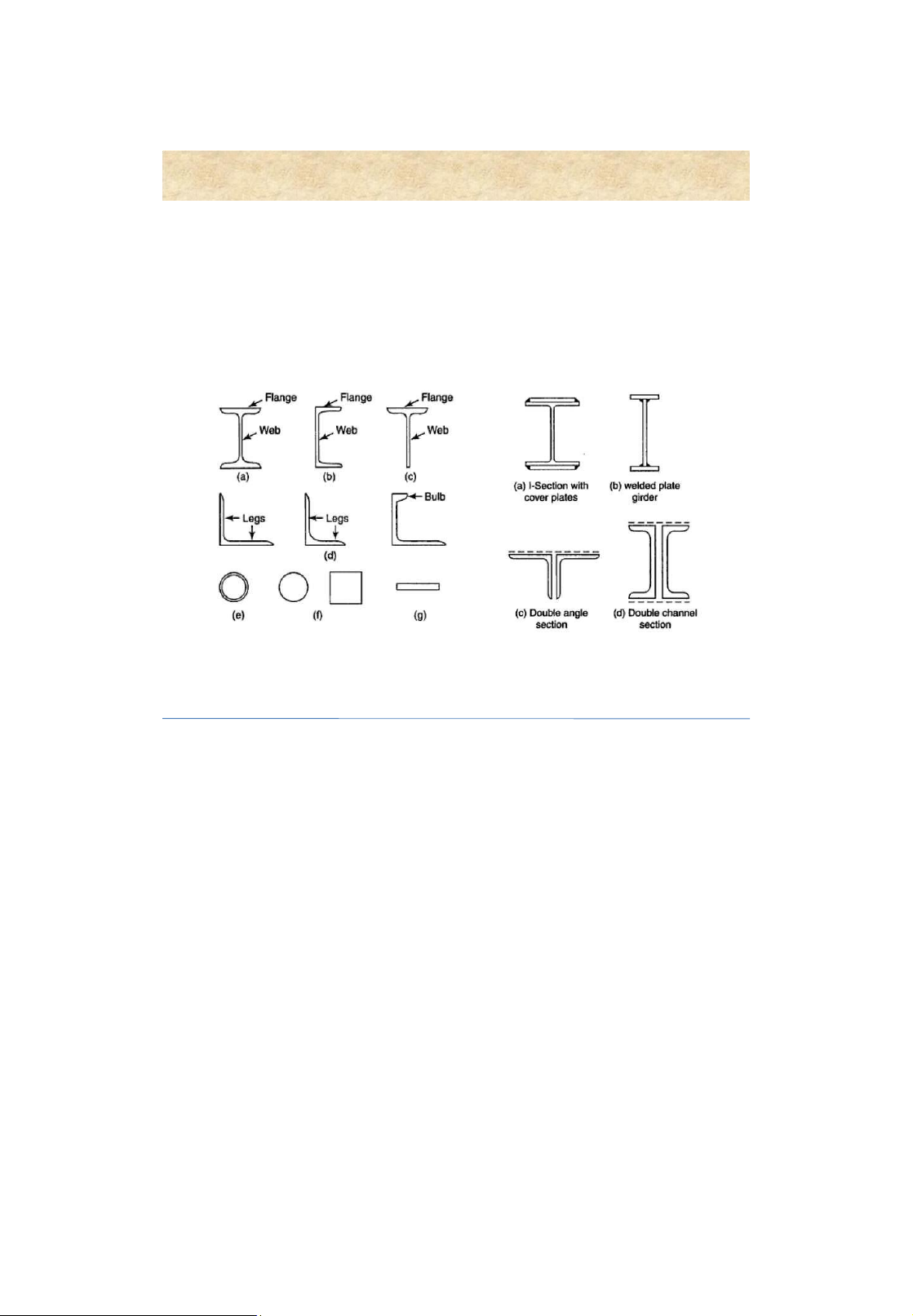
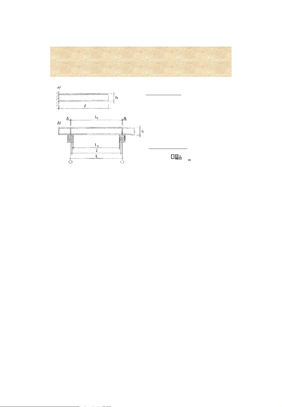
Beams or girders - structural members are subjected to bending lOMoAR cPSD| 58759230 4 Beam section types Rolled sections Built-up sections 5 lOMoAR cPSD| 58759230 General dimensions Span lengths • L 1 : actual ength
• L 0 : clear (unsupported) length • l : effective span length • L : span length Section height , h mi h n hh max
• h min : satisfyingdeflection requirements
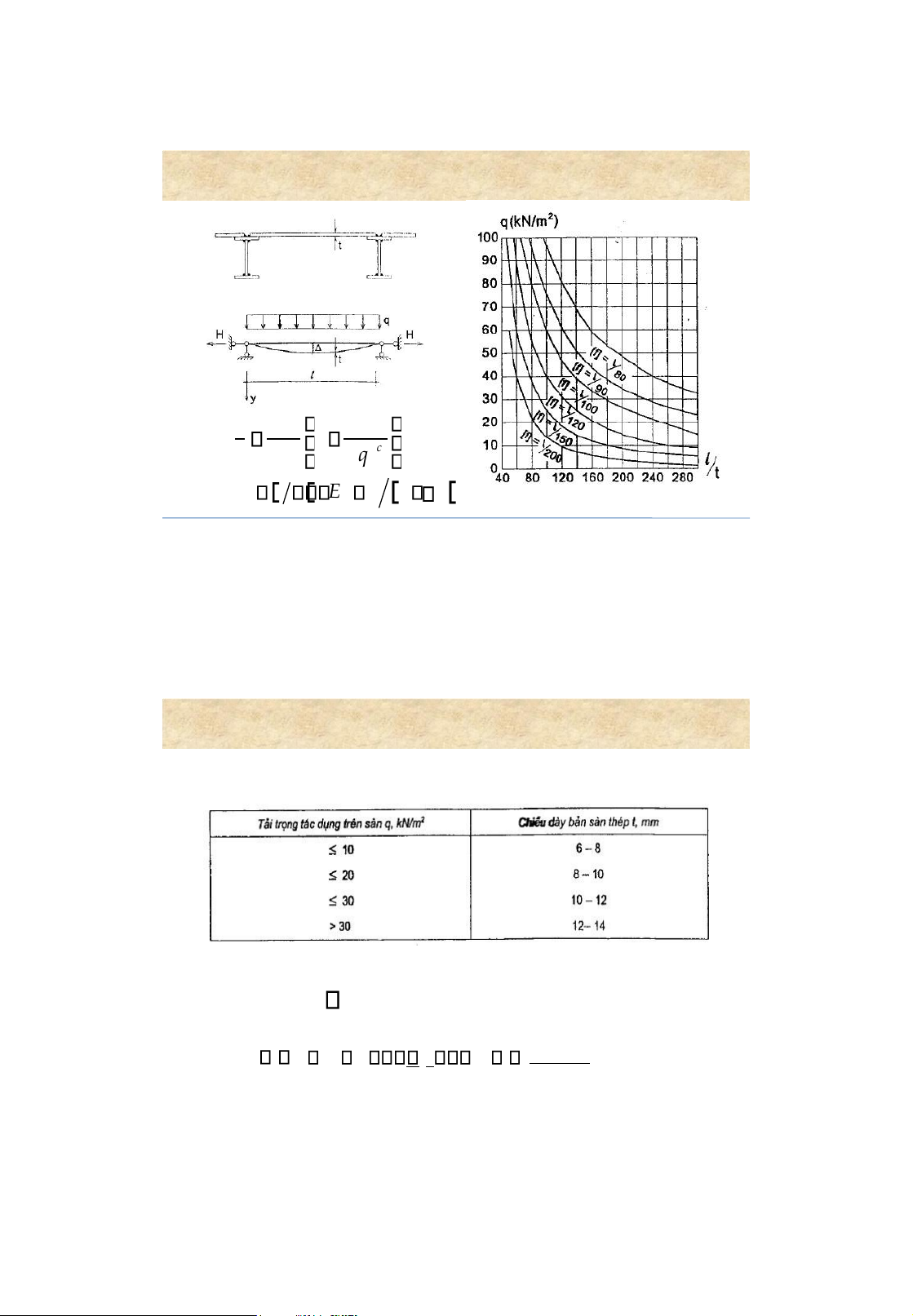
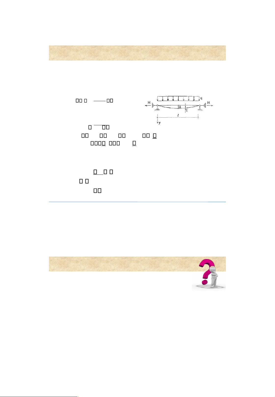
• h max : satisfying function requirements 6 Design of steel floors 1. Selection of l/t lOMoAR cPSD| 58759230 l 4n 72E 0 1 1 4 c t 15 nq 0 n 2 l ; 1 0 E E 1 7 Design of steel floors 2. Select t Uniformed load Floor thickness 3. Calculate (1 )2 3 t0 2 ; 0 3845q lcE I41 8 lOMoAR cPSD| 58759230 Design of steel floors 4. Strength requirement H Mmax c f A Wx Mmax 1M 0 H l2EI or H Q 42 l 2 E t1 2 5. Deflection requirement 0 [ ] 1 9 Rolled steel beams
1. Selection of the beam section lOMoAR cPSD| 58759230 M x x 1 c f 1 c W W req max
c1 =1,12: considering plastic def.
c = 1 : no considering plastic def. 10 lOMoAR cPSD| 58759230 Rolled steel beams
2. Checking for adequate strength Mmax
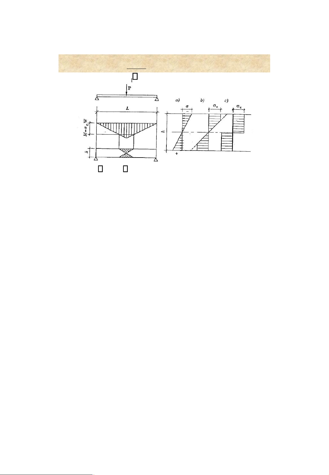
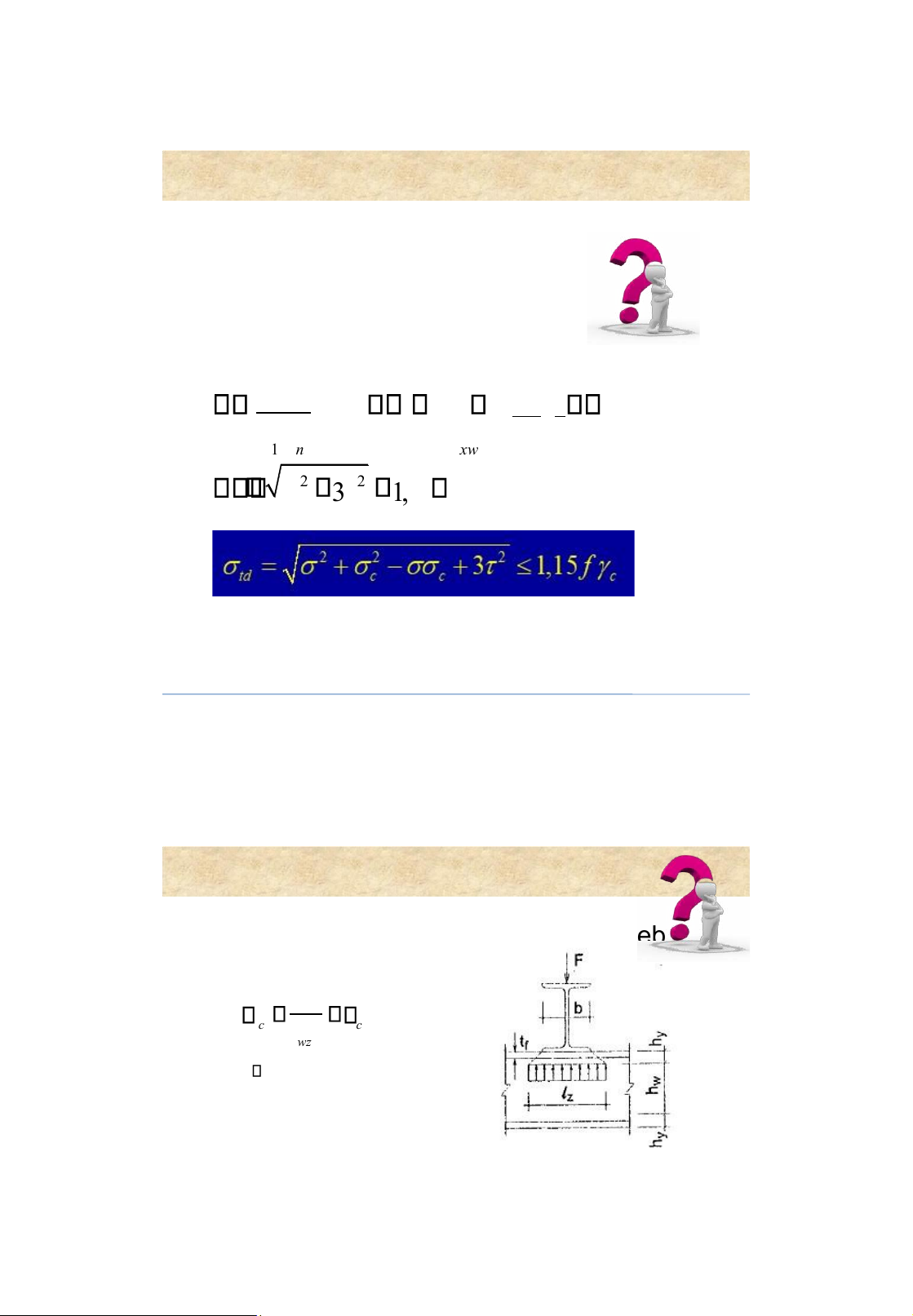
c f ; VmaxSx c fv ; 1 cW nx It xw 2 2 t f 3 1 ,15 c 11 Rolled steel beams 3. Chec
king the strength of the beam web for local load F c c f wz tl c : localstress. t w : webthickness l z = b+2h y = b+2(t f+ r ) lOMoAR cPSD| 58759230 Rolled steel beams
4. Checking the deflection requirement l l 12 5. Checking for general stability Mmax c f bWc
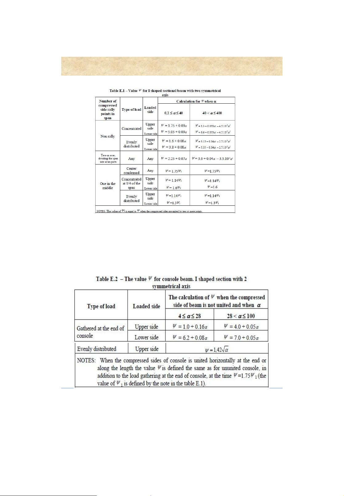
• Wc : beam section modulus in compression • c = 0.95 • 2 b : buckling factor, b 1 y h E
• : depending on (Table 3.3, p. 122)
• l : effective length of the beam 1 l f 0 x o ▪ If 1 0,85 b= 1 It lo 2 ▪ If 1 > 0,85 b= 0,68 + 0,21 1 and b 1 1,54 I y h 13 lOMoAR cPSD| 58759230 Rolled steel beams Rolled steel beams
Moment of inertia in torsion It for rolled I beams 14 Ví dụ:
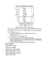
Cho một hệ sàn dầm như hình vẽ có: - B = 6m; L=12m; - Hoạt tải tiêu chuẩn qc=500 daN/m2, hệ số vượt tải 1,1.
Thiết kế sàn thép và dầm
phụ (dầm hình) biết ộ võng
cho phép của bản sàn là L/150 và của dầm phụ là L/350. lOMoAR cPSD| 58759230 Rolled steel beams 15 Built-up beams 1. Configuration of beams 16 lOMoAR cPSD| 58759230 Built-up beams 2. Selection of the beam section Section W height, h h min h k h h kt max tw Weld-beam: k = 1,15 ÷ 1,20 Bolt-beam: k = 1,20 ÷ 1,25 hmin 5 f 1 g pc c l ltb tb gc g pc p 24 E 17 Built-up beams
2 . Selection of the beam section Web thickness , t w max V Sx min 3 max V f t t vc w w xw It 2 wcv h f 3 h t w 7 forh 12 m 1000 w h f t w
for local buckling req. 5 , 5 E hw (m) 1,0 1,5 2,0 3,0 4,0 5,0 lOMoAR cPSD| 58759230 Built-up beams tw (mm) 8-10 10-12 12-14 16-18 20-22 22-24 hw/tw
100-125 125-150 145-165 165-185 185-200 210-230 18
2 . Selection of the beam section ( welds )
Flange dimensions , b f and t f 3 3 h ww th Mmax h ww th I f
Ix Iw W x 212 c f 212 2 2 h h 2 I I f bt f 2 fk fk Af bt f f 4 f f 2 2 hfk • t f > t w • t f 30 mm. • b f/t f 30
• b f= h/ 2 h/5; b f 180 mm; b f h/10 19 lOMoAR cPSD| 58759230 Built-up beams Built-up beams
2 . Selection of the beam section ( bolts )
Flange dimensions, b d and t d 2 Id dd bt 2 1 nh d I d
Ix Iw Ig 3 Mmax h ww th 4 I 2 0 g g aA g c f 212 • b g = 12
h/ h/9; t g = t w ; t g =( b g /11 b g /10) • b d 2 b g + t w • a 1 15 t d ( one plate ) • a 1 8 t d two p ( lates ) 20 3. Chec king for adequate strength for normal stress x x M h 0 max c f 1 cWnx for shear stress max V Sx c fv xw It x x h 0 = h w 21 lOMoAR cPSD| 58759230 Built-up beams Built-up beams
3. Checking for adequate strength
for normal and shear stresses 2 2 t1 3 1 1,15 c f
for normal, shear and local stresses x x h0=hw 2 2 2 t 1
c 1 c 3 1 1,15 c f 1 M1 hw ; 1 V S 1xf ; c F c f Wnx h I tx w t lw z 22 4. Checking for deflection requirement l 2 h E x ol f 0 , 5h fk l lOMoAR cPSD| 58759230 Built-up beams
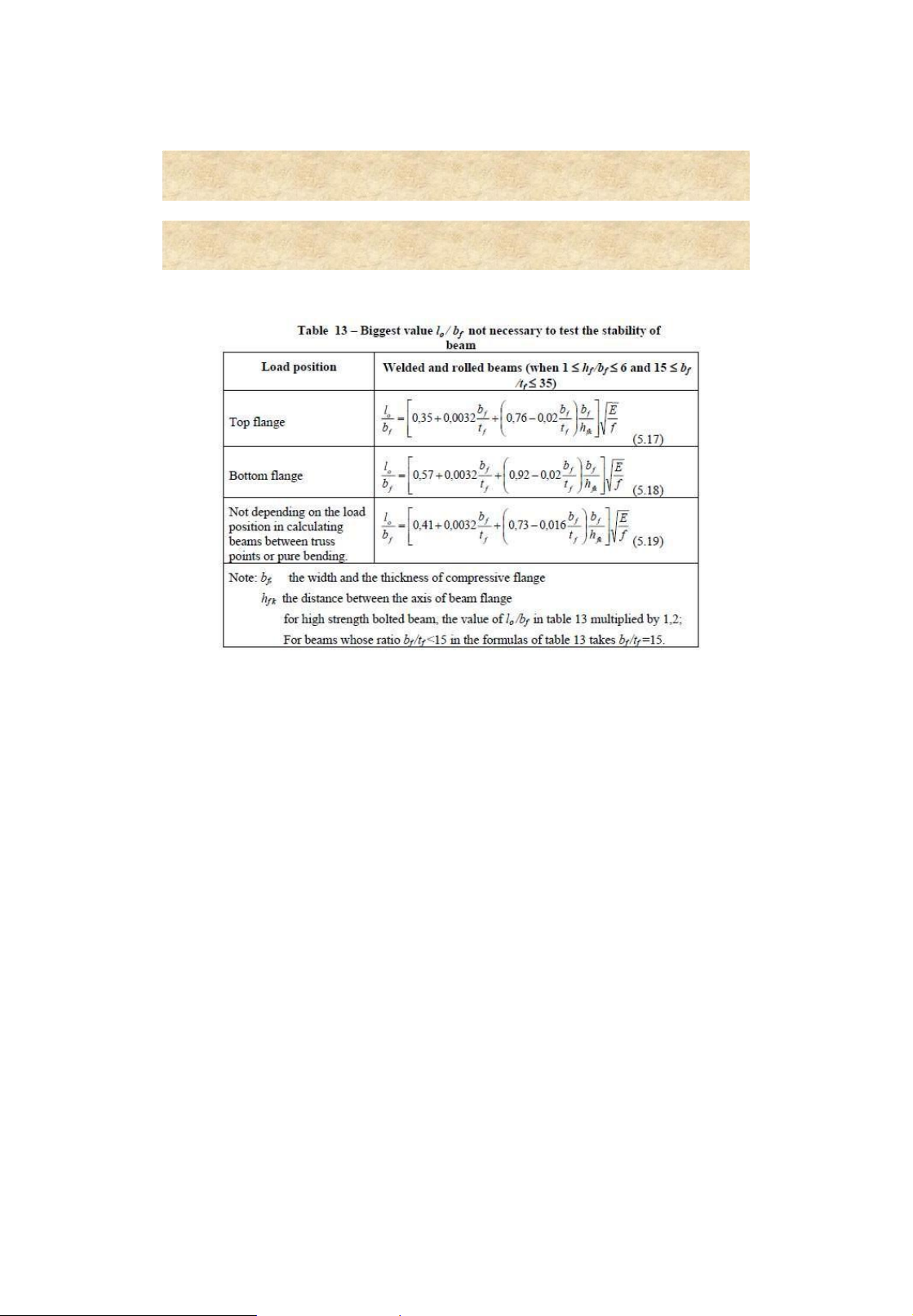
5. Checking for global stability M y b cW f c 1 2 L t 8 h b0 f 1 b tatf w33f ; a fk f
• : depending on (Table 3.3, p. 122)
• l0: effective transverse length of the beam 23 Built-up beams
5. Checking for global stability lOMoAR cPSD| 58759230 Built-up beams 24
5. Checking for global stability 25 lOMoAR cPSD| 58759230 Built-up beams Built-up beams
5. Checking for global stability 26 lOMoAR cPSD| 58759230 Built-up beams
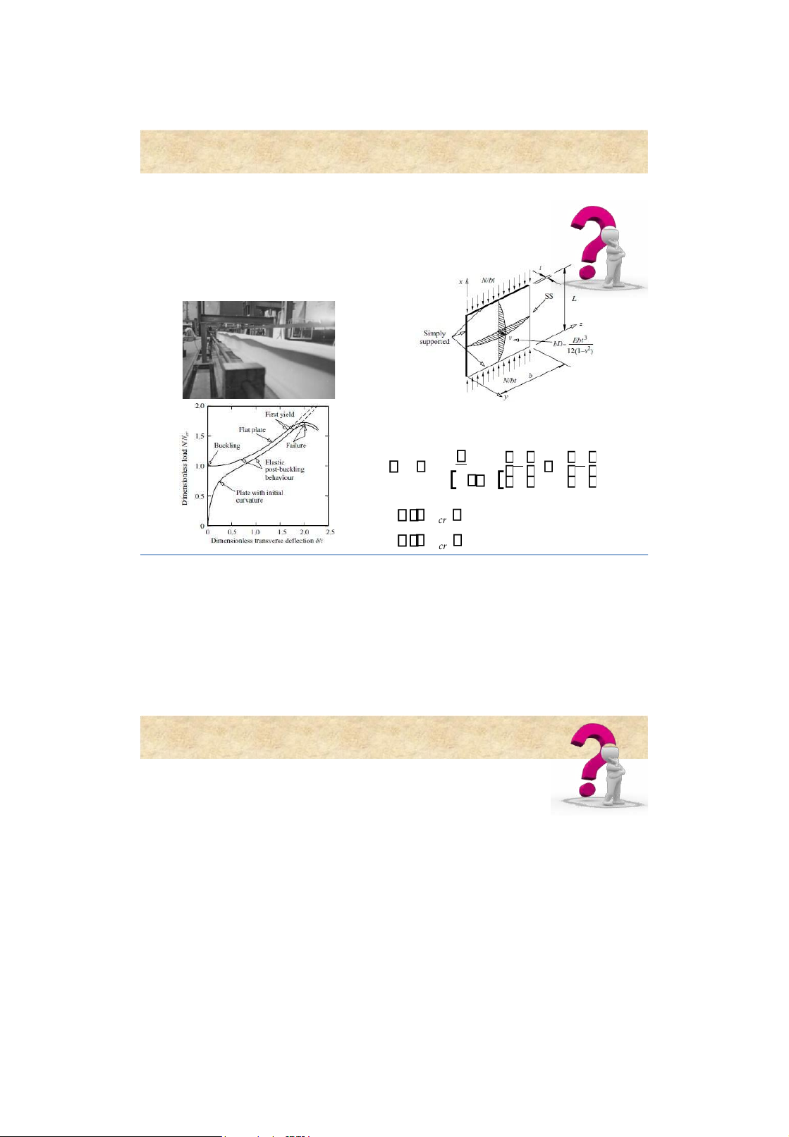
Critical stress ofa plate C 2 2 2 E t t k cr 2 121 b b stable cr unstable cr 27
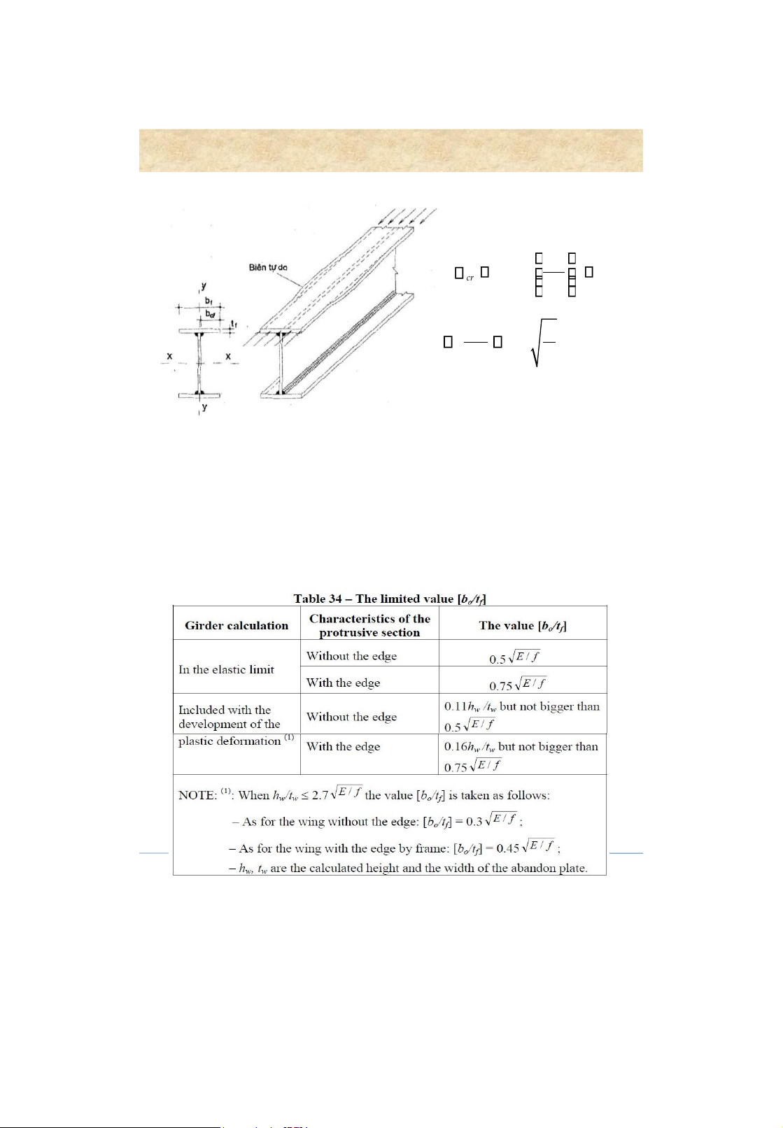
6. Checking for local stability Built-up beams
6. Checking for local stability
Stability of the beam flange in compression lOMoAR cPSD| 58759230 Built-up beams 2 t free edge E cr 0, f 25 f b 0 f b 0f E 0, 5 t f f 28
6. Checking for local stability 29
Tài liệu liên quan:
-
Bài tập chương 6 - Tính toán vách tổ hợp | Môn Kết cấu bê tông & bê tông cốt thép - Đại học Sư phạm Kỹ thuật Thành phố Hồ Chí Minh
93 47 -
Tóm tắt lý thuyết chương 4 Môn Kết cấu bê tông & bê tông cốt thép | Đại học Sư phạm Kỹ thuật Thành phố Hồ Chí Minh
95 48 -
Tóm tắt chương 2 Môn Kết cấu bê tông & bê tông cốt thép | Đại học Sư phạm Kỹ thuật Thành phố Hồ Chí Minh
102 51 -
Tóm tắt chương 2 kết cấu thép: Các loại mối nối và quy trình hàn | Môn Kết cấu bê tông & bê tông cốt thép - Đại học Sư phạm Kỹ thuật Thành phố Hồ Chí Minh
97 49