Control System | Tài liệu Môn Công nghệ kĩ thuật Ô tô Trường đại học sư phạm kỹ thuật TP. Hồ Chí Minh
This Manual consists of five major diagnostic sections for electrical troubleshooting. • Schematic diagrams; • Component location indexes; • Component locations; • Connector configurations; • Harness layouts. The starting point of each system section is the schematic
diagram. These diagrams show how all the components work together, such as electrical current paths from power source to ground(via electrical load), switch connections at each position, and other related circuit functions. Tài liệu giúp bạn tham khảo, ôn tập và đạt kết quả cao. Mời bạn đọc đón xem!
Môn: Công nghệ kĩ thuật oto (OTO21) 155 tài liệu
Trường: Trường Đại học Sư phạm Kỹ thuật Thành phố Hồ Chí Minh 4.4 K tài liệu
Tác giả:


Preview text:
Control System GENERAL SCHEMATIC DIAGRAM COMPONENT LOCATION
CONNECTOR CONFIGURATIONS HARNESS LAYOUTS General
INTRODUCTION . . . . . . . . . . . . . . . . . . . . . . . . . . . . . . . . . . . . . . . . . . . . . . . . . . . . . . . . . . . . . GI- 2
SYMBOLS . . . . . . . . . . . . . . . . . . . . . . . . . . . . . . . . . . . . . . . . . . . . . . . . . . . . . . . . . . . . . . . . . . . GI- 6
TROUBLESHOOTING INSTRUCTIONS . . . . . . . . . . . . . . . . . . . . . . . . . . . . . . . . . . . GI- 9 GI-2 GENERAL INTRODUCTION KFDE6BC0 SCHEMATIC DIAGRAMS
This Manual consists of five major diagnostic sections for
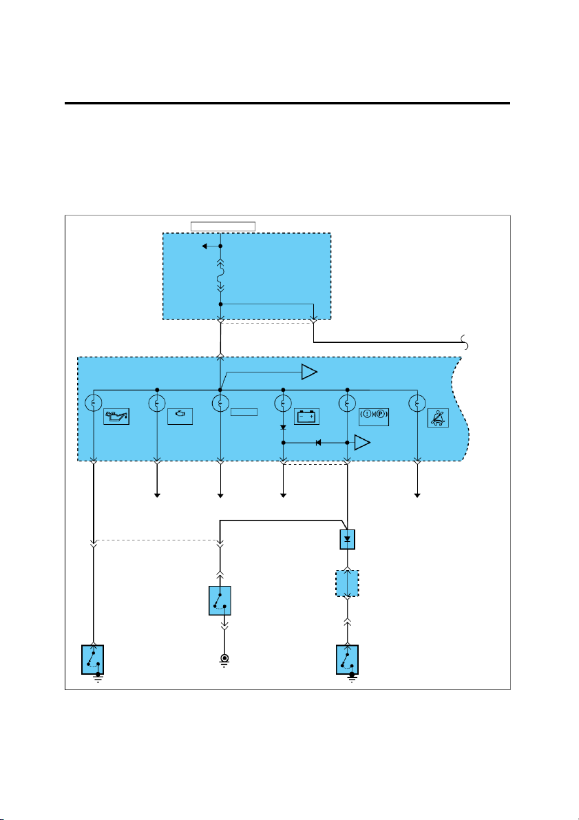
The starting point of each system section is the schematic electrical troubleshooting.
diagram. These diagrams show how all the components
work together, such as electrical current paths from power • Schematic diagrams
source to ground(via electrical load), switch connections
• Component location indexes
at each position, and other related circuit functions. • Component locations
• Connector configurations
It is important to fully understand how a circuit works prior • Harness layouts
to troubleshooting and diagnosis. HOT IN ON OR START PASSENGER See Power COMPARTMENT Distribution JUNCTION on page SD-9 BLOCK FUSE 2 10A 11 12 I/P-H 0.3R/O 0.3R/O 1 M09-1 INSTRUMENT To CLUSTER A Gauge (ECT) on page SD-100 OIL MIL. CRUISE CHARGE BRAKE SEAT PRESSURE WARNING BELT CRUISE CHECK BRAKE To ABS B Active Module on page SD-97 11 M09-3 12 M09-2 2 M09-1 13 14 M09-2 12 M09-3 0.3L/O 0.3Br/O 0.3G/B 0.3R/O 0.3L/B 0.3Y/O See See See See MFI Control System Cruise Control System Charging System ETACS/TACS on page SD-63 on page SD-170 on page SD-56 on page SD-83/SD-87 0.3L/B DIODE Z01 9 19 MC04 0.3L 0.3L 9 M36 JOINT 2 C70 CONNECTOR BRAKE FLUID LEVEL SENSOR 0.5L/O (Closed with 10 M36 low fluid level) 0.3L 5 1 MM02 C70 0.5L 1 C65 0.3B 1 M50 OIL PARKING PRESSURE BRAKE SWITCH SWITCH (Closed with parking brake G23 applied) EGI001A INTRODUCTION GI-3
COMPONENT LOCATION INDEXES
components, connectors, grounds, diodes, and their phys-
ical location and page reference. Almost all components,
When you want to locate the schematic components on the
connectors or grounds, and diodes shown on a schematic
vehicle, use the Component Location Index which follows
can be pinpointed visually by using the Component Loca-
each schematic. A Component Location Index lists major tion Illustrations. Components
Location Reference - Page I12 Digital clock CL-15 I16-1 Instrument cluster CL-15 M55 Fuel sender CL-19 M56 Fuel pump CL-19 C34
Engine coolant temperature sender CL-5, CL-8 Connectors MI01/MI02/MI03 CL-21 MC02 CL-21 CC02 CL-8 Grounds G01 CL-24 G02 CL-24 EGI001B COMPONENT LOCATIONS
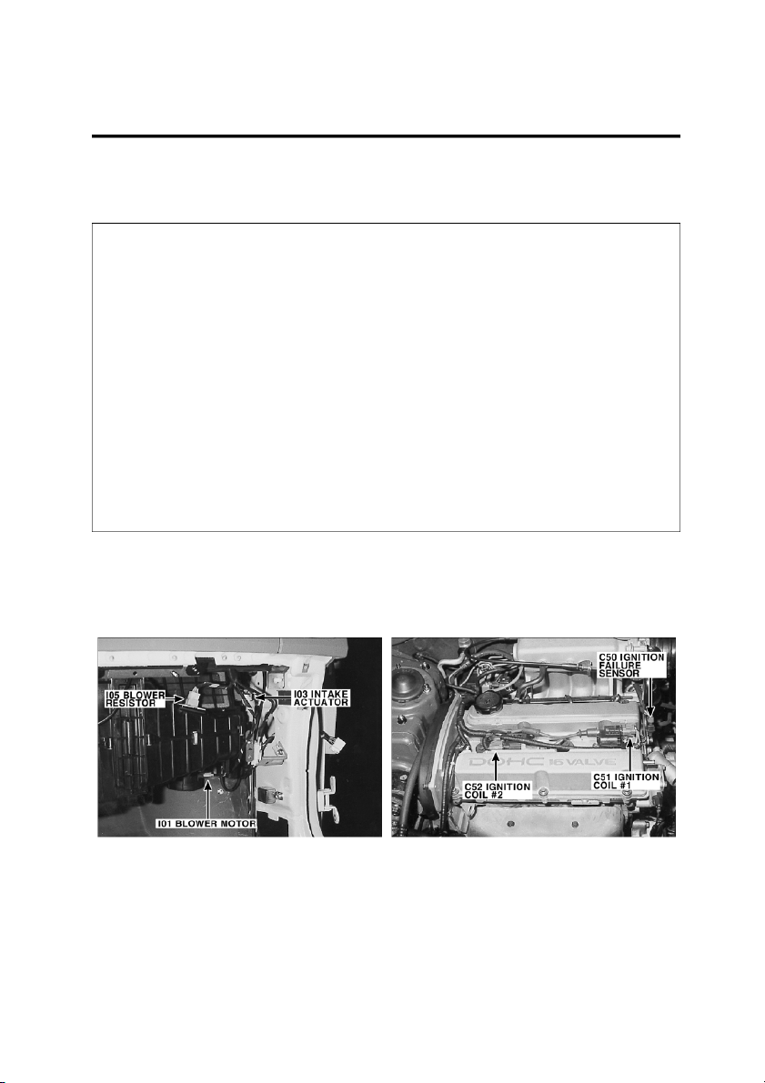
Component Locations make it easy to find the schematic
components on the vehicle shown in the Component Lo- cation Index. EGI001C EGI001D
CONNECTOR CONFIGURATIONS
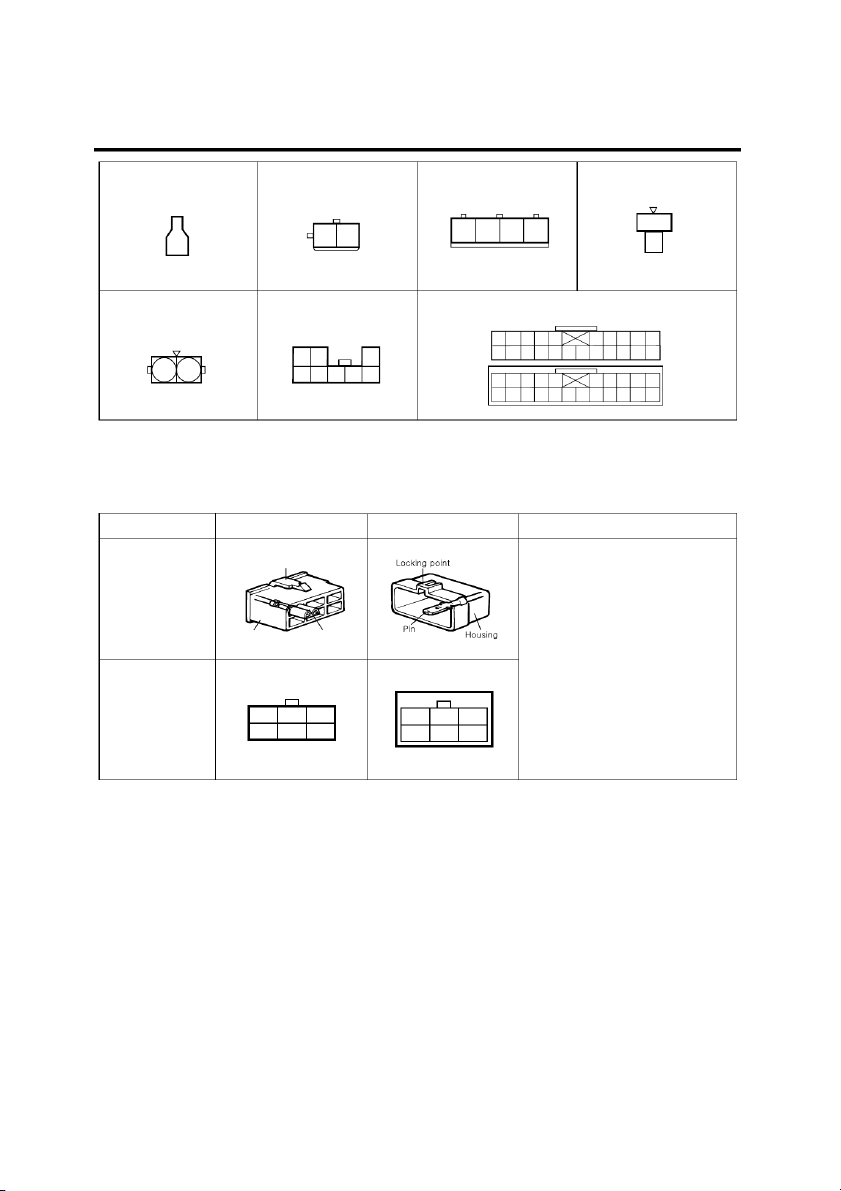
colors and terminal numbers in the schematic. The config-
uration drawings show the connector view as seen from a
This section shows the cavity or terminal locations in all the
component after the harness connector has been discon-
multi-pin connectors shown in the schematic diagrams. It
nected. When more than one connector is connected to a
will help you to locate check points, together with the wire
component, the connectors are all shown together. Both
halves of in-line connectors are shown together. GI-4 GENERAL E37-2 E38 E39 E42 1 2 1 4 3 2 1 1 2 E46 E47 EM01 10 9 8 7 6 5 4 3 2 1
22 21 20 19 18 17 16 15 14 13 12 11 3 2 1 2 1 8 7 6 5 4 1 2 3 4 5 6 7 8 9 10
11 12 13 14 15 16 17 18 19 20 21 22 EGI001E
CONNECTOR VIEW AND NUMBERING ORDER 1. CONNECTOR VIEW Female Male Remarks Actual
It is not the shape of the connector Illustration Locking point housing, but the connector pin
that distinguishes between male or female connectors. When numbering female and male
connectors, refer to the numbering Housing Pin order in the following table.
Some connectors may not follow this Illustration in the method of numbering order. Shop manual
For individual detailed numbering, refer to the CONNECTOR 3 2 1 1 2 3 CONFIGURATIONS. 6 5 4 4 5 6 EGI001F NOTE
UNLESS OTHERWISE STATED, ALL CONNECTOR
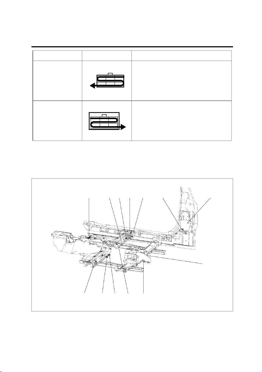
VIEWS ARE FROM THE TERMINAL SIDE OF THE CONNECTOR. 2. NUMBERING ORDER INTRODUCTION GI-5 Numbering order Remarks Female Connector
Numbered in order from upper right to lower left 3 2 1 6 5 4 Male Connector
Numbered in order from upper left to lower right 1 2 3 4 5 6 EGI001G HARNESS LAYOUTS
Harness layouts show the routing of the major wiring har-
nesses, the in-line connectors and the splices between the
major harnesses. These layouts will make electrical trou- bleshooting easier. II01 G09 I19 I15 I16 I18 I20 I10 I09 I12 I13 I14 I11 EGI001H GI-6 GENERAL SYMBOLS KC68AF55
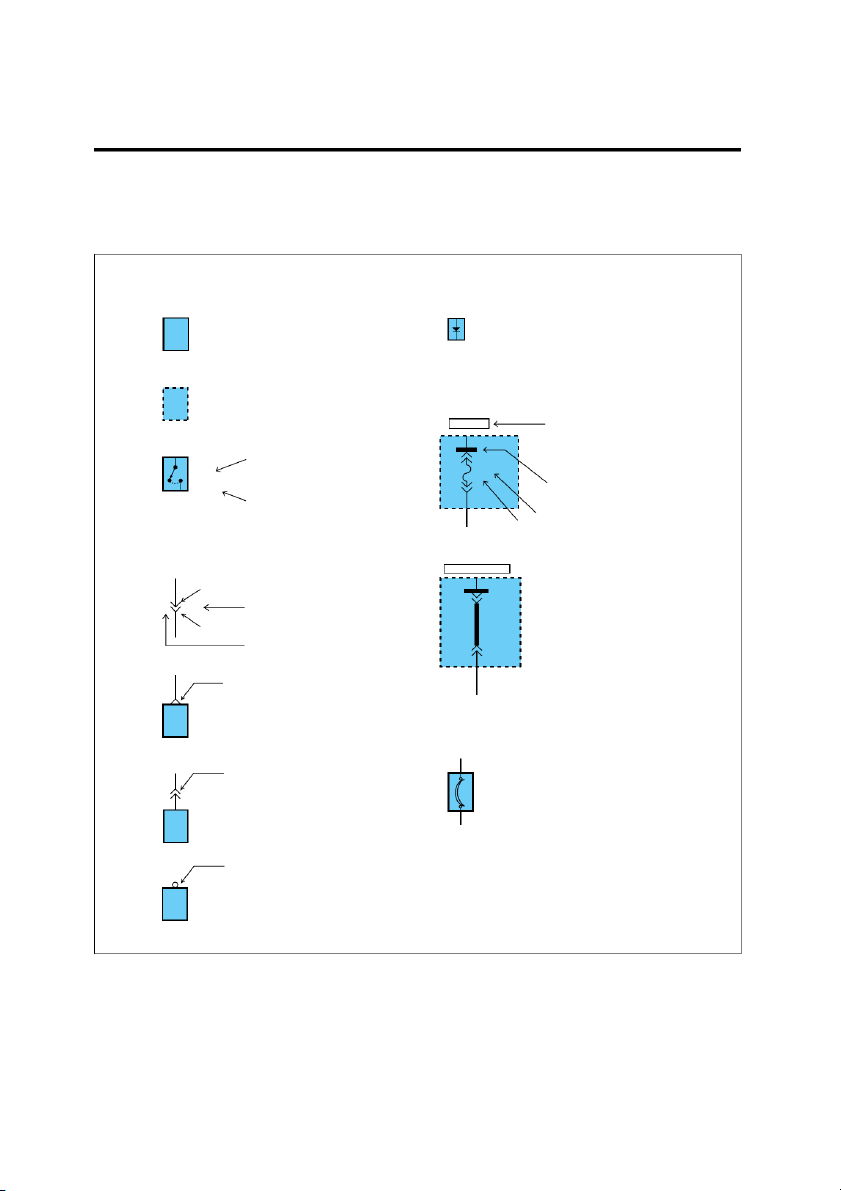
The symbols and abbreviations explained in this section
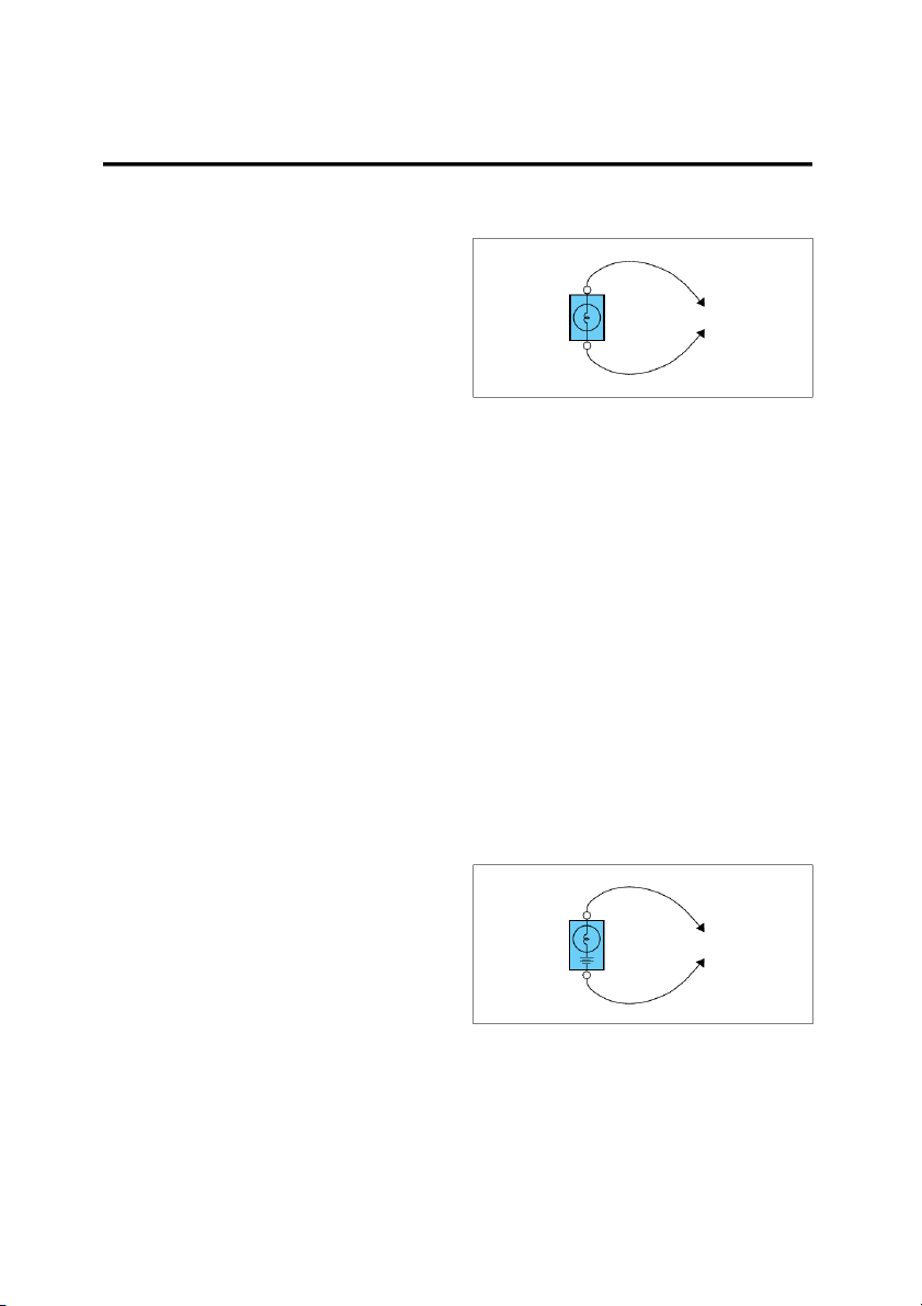
are used throughout the manual. SYMBOLS IN SCHEMATIC Components Diode A solid line means the entire
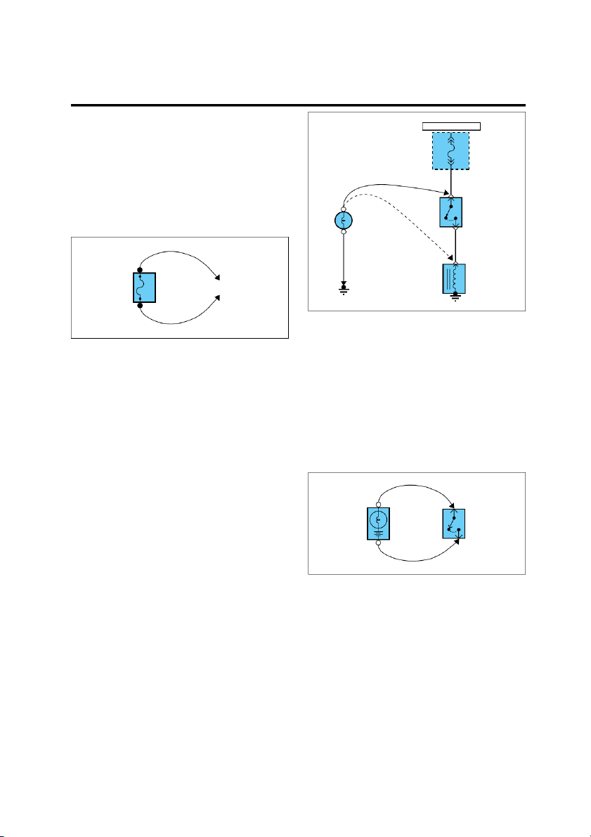
This diode allows current to flow component is shown.
only in the direction of the arrow. A broken line indicates only Fuse and Fusible link
part of the component is shown. HOT IN ON This means power is supplied
with the ignition on position. DASH FUSE BOX STOP The name of the component LAMP
appears next to its upper right FUSE 10 SWITCH corner. 10A Closed This means the short bar with pedal connects to other fuses. depressed Notes about component function follow its name. Identification 0.5L/W Current rating Connectors HOT AT ALL TIMES ENGINE Male COMPARTMENT connector RELAY 10 M05-2 Connector number BOX FUSIBLE Female PINK LINK B connector 30 A Connector cavity number This means the connector con-
nects directly to the component. Circuit Breaker This indicates the connector
Basically a reusable fuse, a circuit connects to a lead (pigtail),
breaker will heat and open if too wired directly to the com- much current flows through it. ponent. Some units automatically reset
when cool, others must be manu- ally reset.
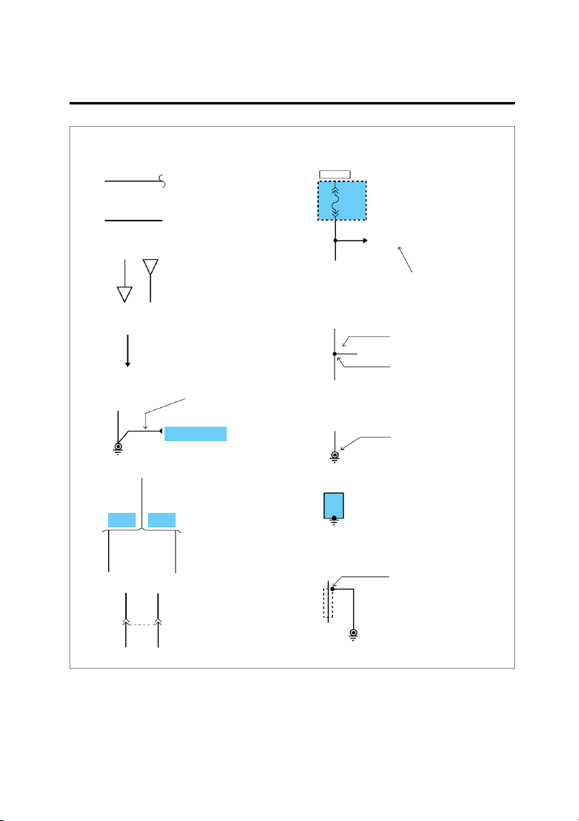
This indicates a screw terminal on the component. EGI002A SYMBOLS GI-7 . Wires HOT IN ON 0.85B A wavy line means the wire is broken but DASH FUSE is to be continued. BOX FUSE 10 10A 0.5Y/R Wire insulation is yellow with a red strip. 0.5L/W See Power Distribution on page SD-15 From C52 on page SD-76 A
Current path is continued on the same page or another page.
Where separate wires join, only
The arrow shows the direction of
the splice is shown: for details
current flow. You should look for
on the additional wiring, refer A
the "A" in the marked position. to the circuit listed. To MC02 on Splices page SD-77 Splice number 0.5L 0.5R A wire connects to another SM05 circuit. The wire is shown 0.5L again on that circuit which Splices are numbered and shown Name of Circuit the arrow is pointing.
as a dot with circle. The exact
location and connection of these
splices may vary among vehicles. A broken line means only some
of the circuit is shown: refer to Ground - "G"
the circuit listed for the com- plete schematic. See Ground Distribution on page SD-23 This symbol means the end of
the wire is attached to a metal part of the vehicle. G06 G06 0.5G
Wire choices for options or dif- This ground symbol (dot and 3 ferent models are labeled and lines overlapping the compo- shown with a "choice" bracket nent) means the housing of the Automatic Manual like this. component is attached to a Transaxle Transaxle metal part of the vehicle. 0.5G 0.5G Shield Wire
This represents RFI (Radio Fre- quency Interference) Shielding
around a wire. The shielding is always connected to ground. 0.5R 0.5Y/L 0.5B This dashed line means the 3 1 MC01 R(red) and Y/L(yellow/blue)
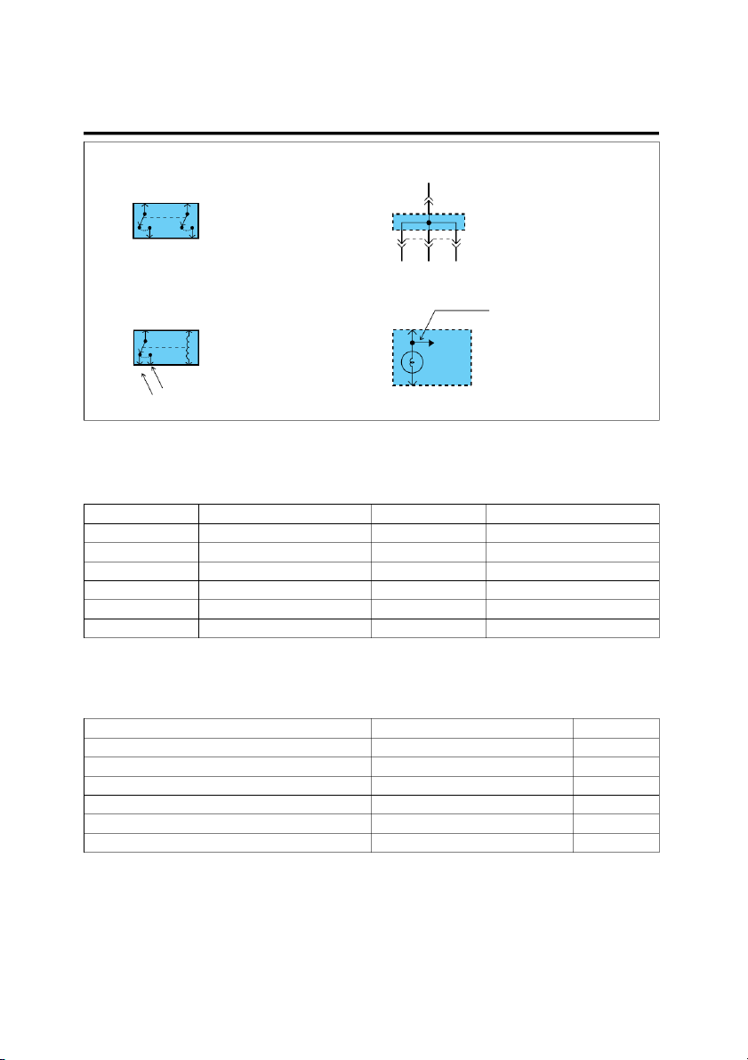
wires are both in connector MC01. 0.5R 0.5Y/L G06 EGI002B GI-8 GENERAL Switches Joint Connectors 4 M03 These switches move together: a dashed line shows a mechani- This is a connector showing cal connection between them. the joining wires. 1 2 3 M03 Relays Indicator
This indicates seat belt warning
indicator continues to other indi- This is a relay shown with no
cators within instrument cluster.
current flowing through its coil. Indicators When a current flows through SEAT BELT coil, contact will toggle. WARNING This is an indicator which INDICATOR displays the lighted symbol. Normally open contact Normally closed contact EGI002C
WIRE COLOR ABBREVIATIONS
The following abbreviations are used to identify wire colors in the circuit schematics. Symbol Color of wire Symbol Color of wire B Black O Orange Br Brown P Pink G Green R Red Gr Gray W White L Blue Y Yellow Lg Light green HARNESS CLASSIFICATION
Electrical wiring connectors are classified according to the
wiring parts in the Harness Layouts. Harness name Location Symbol Engine harness Engine compartment E
Main, Floor, Roof, Sunroof, Seat warmer ext. harness
Passenger compartment, Floor, Roof M Control, Injector harness Engine compartment C Tail gate harness Tail gate R Air bag harness Under crash pad and Floor I Door harness Door D
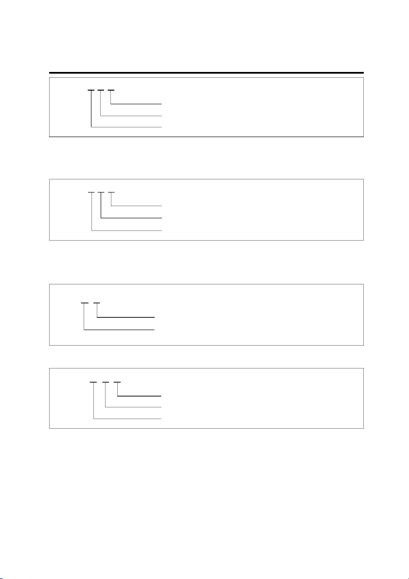
CONNECTOR IDENTIFICATION
connector. These connector locations can be found in the HARNESS LAYOUTS.
A connector identification symbol consists of a wiring
harness location classification symbol corresponding to a For example :
wiring harness location and number corresponding to the
TROUBLESHOOTING INSTRUCTIONS GI-9 E 10 -1
Number corresponding to sub-connector (Serial Number)
Number corresponding to main connector (Serial Number)
Symbol indicating wiring harness (Engine wiring harness) EGI002D NOTE For example :
Connectors which connect each wiring harness are
represented by the following symbols. M R 01
Number corresponding to main connector (Serial Number) Rear wiring harness Main wiring harness EGI002E
JUNCTION BLOCK IDENTIFICATION
wiring harness location and number corresponding to the
connector in the junction block.
A junction block identification symbol consists of a wiring
harness location classification symbol corresponding to a For example : I/P- A Connector name
Abbreviation of the word "Passenger compartment junction block" EGI002F For example : J M 01
Number corresponding to main connector (Serial Number)
Symbol indicating wiring harness prefix(Main)
Abbreviation of the word "Junction" EGI002G TROUBLESHOOTING 1.
Verify the customer’s complaints INSTRUCTIONS K9A93EB1
Turn on all the components in the problem circuit to
TROUBLESHOOTING PROCEDURES
check the accuracy of the customer’s complaints.
Note the symptoms. Do not begin disassembly or
The following five-steps troubleshooting procedure is rec-
testing until you have narrowed down the probable ommended. causes. GI-10 GENERAL 2.
Read and analyze the schematic diagram
A voltmeter can be used in place of a test lamp. While a
test lamp shows whether the voltage is present or not, a
Locate the schematic for the problem circuit. Deter-
voltmeter indicates how much voltage is present.
mine how the circuit is supposed to work by tracing
the current paths from the power source through the
system components to ground. If you do not under-
stand how the circuit should work, read the circuit op-
eration text. Also check other circuits that share with TEST LAMP
the problem circuit. The name of circuits that share
the same fuse, ground, or switch, for example, are re-
ferred to on each diagram. Try to operate any shared
circuits you did not check in step 1. If the shared cir-
cuit works, the shared wiring is okay, and the cause
must be within the wiring used only by the problem cir-
cuit. If several circuits fail at the same time, the fuse EGI003A or ground is a likely cause.
SELF-POWERED TEST LAMP AND OHMMETER 3.
Inspect the circuit/ component with the problem isolated
Use a self-powered test lamp or an ohmmeter to check
for continuity. The ohmmeter shows how much resistance
Make a circuit test to check the diagnosis you made
there is between two points along a circuit. Low resistance
in step 2. Remember that a logical, simple procedure means good continuity.
is the key to efficient troubleshooting. Narrow down CAUTION
the probable causes using the troubleshooting hints
and system diagnosis charts. Test for the most likely
Never use a self-powered test lamp on circuits that
cause of failure first. Try to make tests at points that
contain solid state modules. Damage to these mod- are easily accessible. ules may result. 4. Repair the problem
An ohmmeter can be used in place of a self-powered test
lamp. The ohmmeter shows how much resistance there is
Once the problem is found, make the necessary re-
between two points along a circuit. Low resistance means pairs. good continuity.
Circuits which include any solid-state devices should be 5.
Make sure the circuit works
tested only with a 10-megaohm or higher impedance dig-
ital multimeter. When measuring resistance with a digital
Repeat the system check to be sure you have repaired
multimeter, the battery negative terminal should be dis-
the problem. If the problem was a blown fuse, be sure
connected. Otherwise, there may be incorrect readings.
to test all of the circuits on that fuse.
Diodes and solid-state devices in a circuit can make an
TROUBLESHOOTING EQUIPMENT
ohmmeter give a false reading. To find out if a component
is affecting a measurement, take one reading, reverse the VOLTMETER AND TEST LAMP
leads and take a second reading. If different the solid-state
device is affecting the measurement.
Use a test lamp or a voltmeter on circuits without solid-
state units and use a test lamp to check for voltage. A test
lamp is made up of a 12-volt light bulb with a pair of leads
attached. After grounding one lead, touch the other lead
to various points along the circuit where voltage should be SELF- POWERED
present. When the bulb goes on, there is voltage at the TEST LAMP point being tested.> CAUTION
A number of circuits include solid-state modules,
such as the Engine Control Module(ECM), used EGI003B
with computer command con trol injection. Volt-
age in these circuits should be tested only with a JUMPER WIRE WITH FUSE
10-megaohm or higher impedance digital volt-met er
. Never use a test lamp on circuits that contain solid
Use a jumper wire with a fuse to by-pass an open circuit.
state modules. Damage to the modules may result.
TROUBLESHOOTING INSTRUCTIONS GI-11
A jumper wire is made up of an in-line fuse holder con-
nected to a set of test leads. This tool is available with HOT AT ALL TIMES DASH
small clamp connectors providing adaption to most con- FUSE nectors without damage. BOX CAUTION ON
Do not use a fuse with a higher rating than the speci- 0.85R
fied fuse that protects the circuilt being tested. Do not SWITCH
use this tool in any situation to substitute an input or
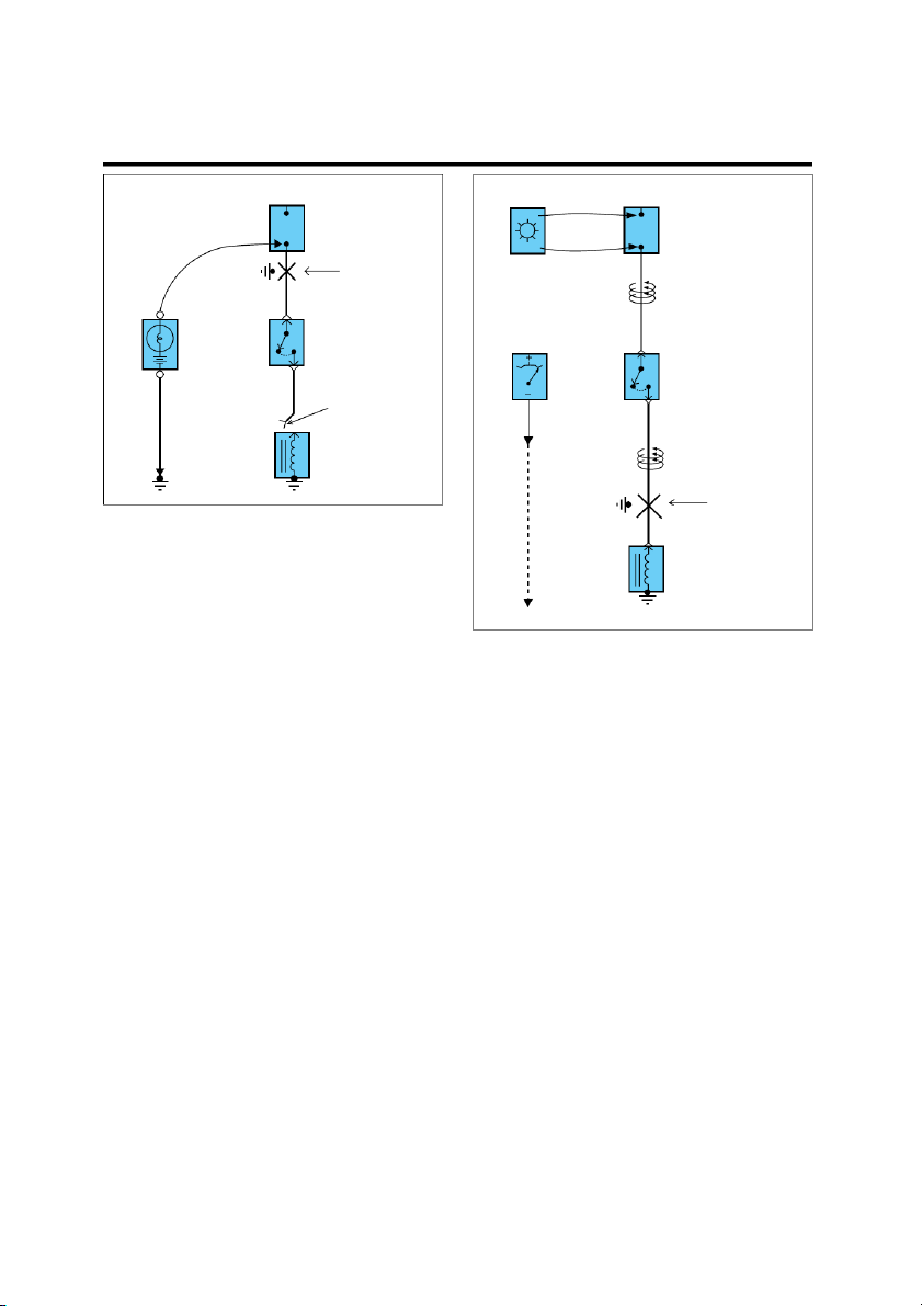
output at the solid-state control module, such as ECM, TEST LAMP OFF OR TCM, etc. VOLTMETER 4 M11 0.85G SOLENOID 5A EGI003D 2. TESTING FOR CONTINUITY EGI003C SHORT FINDER A.
Disconnect the battery negative terminal. B.
Connect one lead of a self-powered test lamp or
A short finder is available to locate a short to ground. The
ohmmeter to one end of the part of the circuit you
short finder creates a pulsing magnetic field in the shorted
wish to test. If you are using an ohmmeter, hold
circuit and shows you the location of the short through
the leads together and adjust the ohmmeter to body trim or sheet metal. read zero ohms. TROUBLESHOOTING TEST C.
Connect the other lead to the other end. D.
If the self-power test lamp glows, there is conti- 1. TESTING FOR VOLTAGE
nuity. If you are using an ohmmeter, low or zero
resistance means good continuity.
This test measures voltage in a circuit. When testing
for voltage at a connector, you do not have to separate
the two halves of the connector. lnstead, probe the
connector from the back(backprobe). Always check
both sides of the connector because dirt and corro- SELF- STOP
sion between its contact surfaces can cause electrical POWERED LAMP problems. TEST LAMP SWITCH OR OHMMETER A.
Connect one lead of a test lamp or voltmeter to
a ground. If you are using a voltmeter, be sure
it is the voltmeter’s negative test lead you have connected to ground. EGI003E B.
Connect the other lead of the test lamp or volt-
meter to a selected test point(connector or termi- 3.
TESTING FOR SHORT TO GROUND nal). C.
If the test lamp glows, there is voltage present. If A.
Disconnect the battery negative terminal.
you are using a voltmeter, note the voltage read- B.
Connect one lead of a self-powered test lamp or
ing. A loss of more than 1 volt from specification
an ohmmeter to the fuse terminal on the load indicates a problem. side. C.
Connect the other lead to a ground. D.
Beginning near the fuse block move the har-
ness from side to side. Continue this procee-
dure(about six inches apart) while watching the
self-powered test lamp or ohmmeter. E.
When the self-powered test lamp glows, or ohm-
meter registers, there is a short to a ground in the wiring near that point. GI-12 GENERAL Battery Battery disconnected disconnected FUSE BOX FUSE BOX (Fuse removed) (Fuse removed) SHORT Short to ground FINDER Pulsing 0.85R magnetic field 1 M11 SELF-POWERED SWITCH 0.85R TEST LAMP OR 1 M11 VOLTMETER METER SWITCH 4 M11 0.85G Load 4 M11 disconnected 0.85G SOLENOID Move meter Pulsing along wire magnetic field Short to ground EGI003F 4.
TESTING FOR A SHORT WITH A SHORT FINDER SOLENOID A.
Remove the blown fuse. Leave the battery con- nected. B.
Connect the short finder across the fuse termi- Needle stops moving here nals. C.
Close all switches in series in the circuit that is EGI003G being tested. D.
Turn on the short circuit locator. It sends pulses
of current to the short. This creates a pulsing
magnetic field around the wiring between the fuse box and the short. E.
Beginning at the fuse box, slowly move the short
finder along the circuit wiring. The meter will
show current pulses through sheet metal and
body trim. As long as the meter is between the
fuse and the short, the needle will move with
each current pulse. Once the meter is moved
past the point of the short, the needle will stop
moving. Check around this area to locate the cause of the short circuit. Schematic Diagram
FUSE AND RELAY INFORMATION . . . . . . . . . . . . . . . . . . . . . . . . . . . . . . . . . . . . . . . SD- 2
POWER DISTRIBUTION . . . . . . . . . . . . . . . . . . . . . . . . . . . . . . . . . . . . . . . . . . . . . . . . . . . SD- 6
FUSE BOX DETAILS . . . . . . . . . . . . . . . . . . . . . . . . . . . . . . . . . . . . . . . . . . . . . . . . . . . . . . . SD- 8
GROUND DISTRIBUTION . . . . . . . . . . . . . . . . . . . . . . . . . . . . . . . . . . . . . . . . . . . . . . . . . SD-14
VEHICLE SPEED SENSOR & TACHOGRAPH . . . . . . . . . . . . . . . . . . . . . . . . . . . SD-18
STARTING & CHARGING SYSTEM . . . . . . . . . . . . . . . . . . . . . . . . . . . . . . . . . . . . . . . SD-20
PREHEATING SYSTEM . . . . . . . . . . . . . . . . . . . . . . . . . . . . . . . . . . . . . . . . . . . . . . . . . . . . SD-22
OVERHEAT WARNING SYSTEM . . . . . . . . . . . . . . . . . . . . . . . . . . . . . . . . . . . . . . . . . . SD-24
PREHATER CONTROLS . . . . . . . . . . . . . . . . . . . . . . . . . . . . . . . . . . . . . . . . . . . . . . . . . . . SD-26
EXHAUST BRAKE SYSTEM . . . . . . . . . . . . . . . . . . . . . . . . . . . . . . . . . . . . . . . . . . . . . . SD-28
ACCELERATOR INTERLOCK SYSTEM . . . . . . . . . . . . . . . . . . . . . . . . . . . . . . . . . . SD-30
ANTI-LOCK BRAKE SYSTEM (ABS) . . . . . . . . . . . . . . . . . . . . . . . . . . . . . . . . . . . . . SD-32
CLOCK & CIGARETTE LIGHTER . . . . . . . . . . . . . . . . . . . . . . . . . . . . . . . . . . . . . . . . . SD-36
ETACS (ELECTORONIC TIME AND ALARM CONTOL SYSTEM) . . . . . . SD-40
FRONT WIPER AND WASHER . . . . . . . . . . . . . . . . . . . . . . . . . . . . . . . . . . . . . . . . . . . . SD-42
REAR WIPER AND WASHER . . . . . . . . . . . . . . . . . . . . . . . . . . . . . . . . . . . . . . . . . . . . . SD-44
SAFETY DOOR SYSTEM . . . . . . . . . . . . . . . . . . . . . . . . . . . . . . . . . . . . . . . . . . . . . . . . . . SD-46
INDICATORS . . . . . . . . . . . . . . . . . . . . . . . . . . . . . . . . . . . . . . . . . . . . . . . . . . . . . . . . . . . . . . . SD-48
GAUGES . . . . . . . . . . . . . . . . . . . . . . . . . . . . . . . . . . . . . . . . . . . . . . . . . . . . . . . . . . . . . . . . . . . . SD-52
HIGH SPEED WARNING SYSTEM . . . . . . . . . . . . . . . . . . . . . . . . . . . . . . . . . . . . . . . . SD-54
POWER DOOR SYSTEM . . . . . . . . . . . . . . . . . . . . . . . . . . . . . . . . . . . . . . . . . . . . . . . . . . SD-56
OUTSIDE MIRROR DEFOGGER . . . . . . . . . . . . . . . . . . . . . . . . . . . . . . . . . . . . . . . . . . SD-58
AUDIO & HORN SYSTEM . . . . . . . . . . . . . . . . . . . . . . . . . . . . . . . . . . . . . . . . . . . . . . . . . SD-60
HEAD LAMPS . . . . . . . . . . . . . . . . . . . . . . . . . . . . . . . . . . . . . . . . . . . . . . . . . . . . . . . . . . . . . . SD-64
TURN, HAZARD LAMPS & BACK-UP LAMPS . . . . . . . . . . . . . . . . . . . . . . . . . . . SD-66
FRONT FOG LAMPS . . . . . . . . . . . . . . . . . . . . . . . . . . . . . . . . . . . . . . . . . . . . . . . . . . . . . . . SD-70
REAR FOG LAMPS . . . . . . . . . . . . . . . . . . . . . . . . . . . . . . . . . . . . . . . . . . . . . . . . . . . . . . . . SD-72
ROOM LAMPS . . . . . . . . . . . . . . . . . . . . . . . . . . . . . . . . . . . . . . . . . . . . . . . . . . . . . . . . . . . . . . SD-74
TAIL, PARKING & LICENSE LAMPS . . . . . . . . . . . . . . . . . . . . . . . . . . . . . . . . . . . . . SD-76
READING LAMPS . . . . . . . . . . . . . . . . . . . . . . . . . . . . . . . . . . . . . . . . . . . . . . . . . . . . . . . . . . SD-78
STOP LAMPS . . . . . . . . . . . . . . . . . . . . . . . . . . . . . . . . . . . . . . . . . . . . . . . . . . . . . . . . . . . . . . . SD-80
COURTESY LAMPS . . . . . . . . . . . . . . . . . . . . . . . . . . . . . . . . . . . . . . . . . . . . . . . . . . . . . . . SD-82
ILLUMINATIONS . . . . . . . . . . . . . . . . . . . . . . . . . . . . . . . . . . . . . . . . . . . . . . . . . . . . . . . . . . . SD-84
HEATER & VENTILATOR CONTROL SYSTEM . . . . . . . . . . . . . . . . . . . . . . . . . . SD-88
A/C CONTROLS . . . . . . . . . . . . . . . . . . . . . . . . . . . . . . . . . . . . . . . . . . . . . . . . . . . . . . . . . . . . SD-92 SD-2 SCHEMATIC DIAGRAM
FUSE AND RELAY INFORMATION E21BF1AC FUSE BOX LAYOUT SPARE SPARE SPARE SPARE SPARE FUSE 5A 10A 15A 15A 20A PULLER 1 2 3 4 5 6 7 8 9 10 11 12 5A 10A 10A 10A 10A 10A 15A 10A 10A 10A 10A 10A 13 14 Not 16 17 18 19 20 21 Not 23 24 15A 15A used 20A 15A 20A 15A 15A 15A used 10A 5A 25 26 27 28 29 30 31 32 Not 34 35 36 10A 15A 15A 10A 15A 15A 10A 15A used 10A 15A 10A E2QD001A
FUSE AND RELAY INFORMATION SD-3 CIRCUIT Fuse No. Amperages(A) Circuit protected 1 5A Head lamps, Reading lamps 2 10A
Instrument cluster, ETACM, High speed warning, Generator 3 10A Hazard warning 4 10A Ventilator switch 5 10A
Accelerator interlock, Back-up lamp switch, Overheat warning 6 10A Rear wiper & washer 7 15A
Door open switch, Folding door, Swing door 8 10A Heater, A/con 9 10A Wiper & Washer 10 5A DBR, Cold start 11 5A ABS 12 10A Preheater 13 15A Head lamp (High) 14 15A Head lamp (Low) 15 - Not used 16 20A Not used 17 15A
Audio, Clock, Cigarette lighter 18 20A Condenser relay 19 15A Evaporator relay 20 15A Evaporator relay 21 15A Evaporator relay 22 - Not used 23 10A Room lamp, Tachograph, ETACM 24 5A Not used 25 10A Tail lamp 26 15A Not used 27 15A
ETACM, Audio, Room lamp, Luggage lamp, Instrument cluster 28 10A Horn, Hazard warning 29 15A Blower motor relay 30 15A Rear heater 31 10A Fog lamp 32 15A Preheater 33 - Not used 34 10A Reading lamp 35 15A ABS 36 10A
Stop lamp, Accelerator interlock E2QD001B SD-4 SCHEMATIC DIAGRAM RELAY BOX LAYOUT M01 M02 M03 FOG LAMP TAIL LAMP HAZARD FLASHER UNIT M07 M06 M94 M96 REAR WIPER READING OVERHEAT HEAT MIRR LAMP M08 M09 M10 M11 M12 M13 WIPER WIPER HEAD HEAD DBR (HIGH) (LOW) LAMP LAMP (HIGH) (LOW) M14 M15 M16 M17 M05 EVAPORATOR.1 EVAPORATOR. 2 EVAPORATOR.3 REAR ACC HEATER INT RELAY E2QD001C
Tài liệu liên quan:
-
Bài thu hoạch cá nhân phòng Bosch và hộ số ly hợp kép | Nghành công nghệ kỹ thuật ô tô Trường đại học sư phạm kỹ thuật TP. Hồ Chí Minh
334 167 -
Động cơ tỉ nén biến thiên | Tiểu luận môn Công nghệ kĩ thuật ô tô Trường đại học sư phạm kỹ thuật TP. Hồ Chí Minh
530 265 -

Báo cáo thực tập tốt nghiệp: Công ty Cổ Phần Ôtô Kim Thanh | Báo cáo môn Công nghệ kĩ thuật ô tô Trường đại học sư phạm kỹ thuật TP. Hồ Chí Minh
1.2 K 576 -
Báo cáo thực tập hệ thống truyền động servo | Báo cáo môn Công nghễ kĩ thuật ô tô Trường đại học sư phạm kỹ thuật TP. Hồ Chí Minh
592 296 -

Hệ thống truyền lực trên ô tô (powertrain system) | Bài giảng môn Công nghễ kĩ thuật ô tô Trường đại học sư phạm kỹ thuật TP. Hồ Chí Minh
890 445