Lab 2 Kirchoff’s Current And Voltage Laws | Môn Electrical Engineering - Trường Đại học Quốc tế, Đại học Quốc gia Thành phố Hồ Chí Minh
Lab 2 Kirchoff’s Current And Voltage Laws Môn Electrical Engineering. Tài liệu được sưu tầm gồm 13 trang, giúp bạn ôn tập tốt hơn. Mời các bạn đón xem.
Môn: Electrical Engineering 8 tài liệu
Trường: Trường Đại học Quốc tế, Đại học Quốc gia Thành phố Hồ Chí Minh 2 K tài liệu
Tác giả:

Preview text:
lOMoAR cPSD| 58583460 International University Principles of EE I
School of Electrical Engineering EE052IU
Principles of EE I Laboratory Lab 2
Kirchoff’s Current And Voltage Laws Student A Student B Full name: Full name:
…………………………………
………………………………… Student number: Student number:
…………………………………
………………………………… I. Objectives
In this laboratory, you will investigate:
1. The relationship of Ohm's Law.
2. The Kirchhoff’s Current Law (KCL). lOMoAR cPSD| 58583460 International University Principles of EE I
School of Electrical Engineering EE052IU
3. The Kirchhoff’s Voltage Law (KVL).
4. The "equivalent resistance" for both series and parallel circuits. II.Procedure
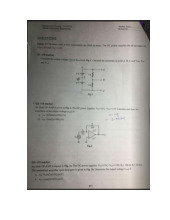
*You must provide all calculations in-details in separate sheets or simulation results as attachments. Student’s Activities Kirchoff’s Laws
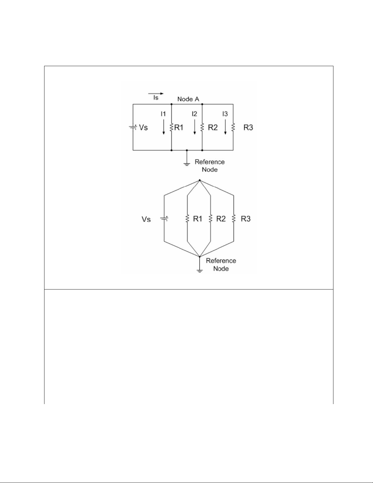
Using the adjustable D.C. power supply and circuit breadboard, connect the resistors into
a two-node circuit as shown below. Note that all four circuit elements are connected between
those two nodes have the source voltage Vs across each of the three resistors. Let the resistors
in the circuit be implemented using the set of the following table. 1000 ohm, 5% 2200 ohm, 5% Set 1 3300 ohm, 5% 3900 ohm, 2% 4700 ohm, 5% Set 2 5600 ohm, 1% 2200 ohm, 5% 4700 ohm, 1% Set 3 5600 ohm, 2% lOMoAR cPSD| 58583460 International University Principles of EE I
School of Electrical Engineering EE052IU Figure II-1
1. Note the color code on each resistor and match it up with its nominal value.
2. Calculate all four currents, (I1, I2, I3, and Is), in your circuit with Vs=15V(VDC).
3. Measure all four currents, (I1, I2, I3, and Is), in your simulation circuit with
Vs=15V(VDC).
4. Measure all four currents, (I1, I2, I3, and Is), in an actual circuit with Vs=15V(VDC) using the DMM.
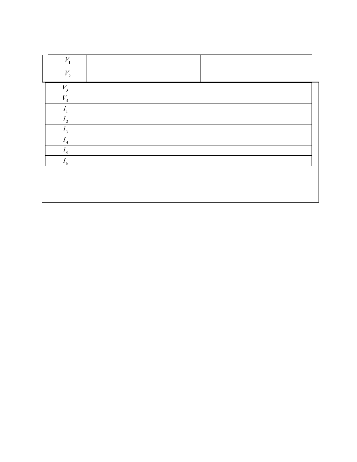
5. Fill the table below with calculated values, simulated values, and the measured values. lOMoAR cPSD| 58583460 International University Principles of EE I
School of Electrical Engineering EE052IU
6. Compare simulated current values with the set of calculated values. Is there any
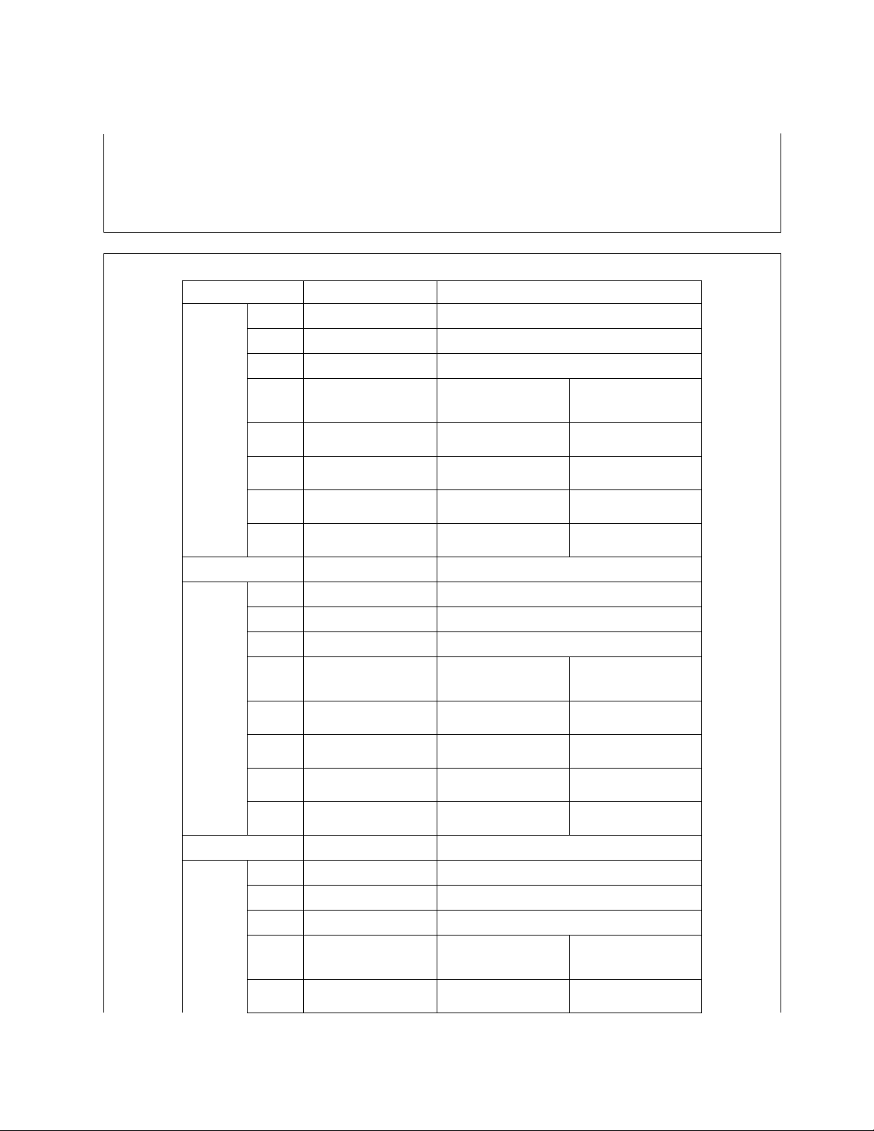
difference? Are the differences between the simulated values and the values calculated within your expectations? Table II-1 Notations Actual Values Color code R1 0.9922kOhm Brown Black Red Gold R2 2.1678kOhm Red red red gold R3 3.2752kOhm Orange orange red gold Calculated Simulated Measured Values Values Values Set 1 IS I1 I2 I3 Notations Actual Values Color code R1 3.834kOhm Orange white red gold R2 4.618kOhm Yellow violet red gold R3 5.492kOhm Green blue red gold Calculated Simulated Measured Values Values Values Set 2 IS I1 I2 I3 Notations Actual Values Color code R1 2.1678kOhm Red red brown gold R2 4.618kOhm Yellow violet red brown R3 5.492kOhm Green blue red red Set 3 Calculated Simulated Measured Values Values Values IS lOMoAR cPSD| 58583460 International University Principles of EE I
School of Electrical Engineering EE052IU I1 I2 I3
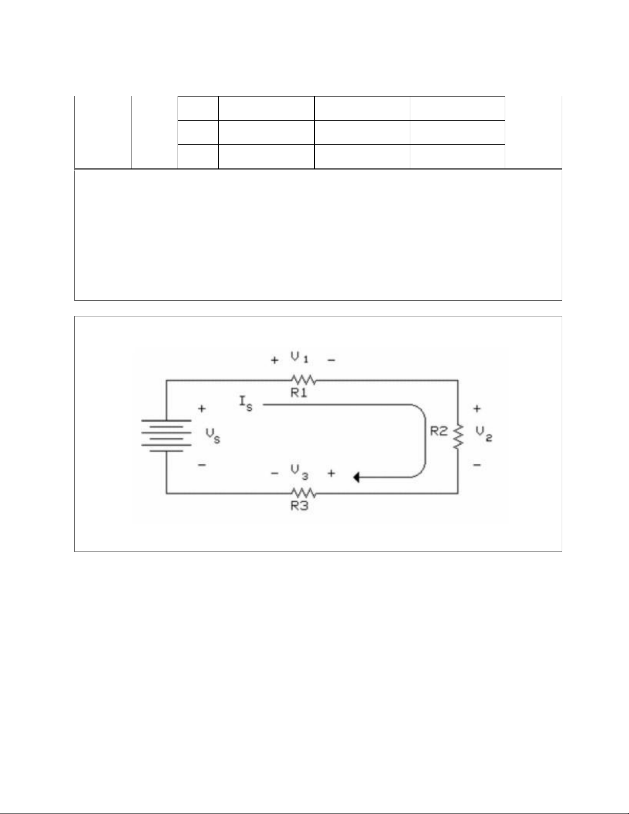
Using the adjustable D.C. power supply and the circuit bread board, connect the resistors into
a circuit as shown below. Note that the three resistors are in series so that the same current
(Is) flows through each resistor. Let the resistors in the circuit be implemented using the set of
the table at the beginning of the Lab manual. Figure II-2 lOMoAR cPSD| 58583460 International University Principles of EE I
School of Electrical Engineering EE052IU
1. Note the color code on each resistor and match it up with its nominal value.
2. Calculate the three voltages and total current, (V1, V2, V3, and Is), in your circuit with
Vs=20V(VDC).
3. Measure the three voltages and total current, (V1, V2, V3, and Is), in your simulation
circuit with Vs=20V(VDC).
4. Fill the table below with calculated value versus the simulated value.
5. Use your simulated voltage values to determine if KVL is verified, in other words,
whether if KVL is correct or not. Also use Ohm's Law and nominal resistance values to
calculate V1, V2, and V3, then use KVL to check back with the source voltage Vs.
6. Compare simulated current values with the set of calculated values. Is there any
difference? Are the differences between the simulated values and the values calculated within your expectations? Table II-2 Notations Actual Values Color code R1 0.9922kOhm Brown Black Red Gold R2 2.1678kOhm Red red red gold R3 3.2752kOhm Orange orange red gold Calculated Simulated Measured Values Values Values Set 1 IS V1 2.31V V2 5.039V V3 7.612V Notations Actual Values Color code R1 3.834kOhm Orange white red gold R2 4.618kOhm Yellow violet red gold Set 2 R3 5.492kOhm Green blue red gold Calculated Simulated Measured Values Values Values lOMoAR cPSD| 58583460 International University Principles of EE I
School of Electrical Engineering EE052IU IS V1 4.113V V2 4.956V V3 5.887V Notations Actual Values Color code R1 2.1678kOhm Red red brown gold R2 4.618kOhm Yellow violet red brown R3 5.492kOhm Green blue red red Calculated Simulated Measured Values Values Values Set 3 IS V1 2.643V V2 5.628V V3 6.686V lOMoAR cPSD| 58583460 International University Principles of EE I
School of Electrical Engineering EE052IU
Series-parallel circuit
Using the adjustable D.C. power supply and circuit bread board, connect the resistors into
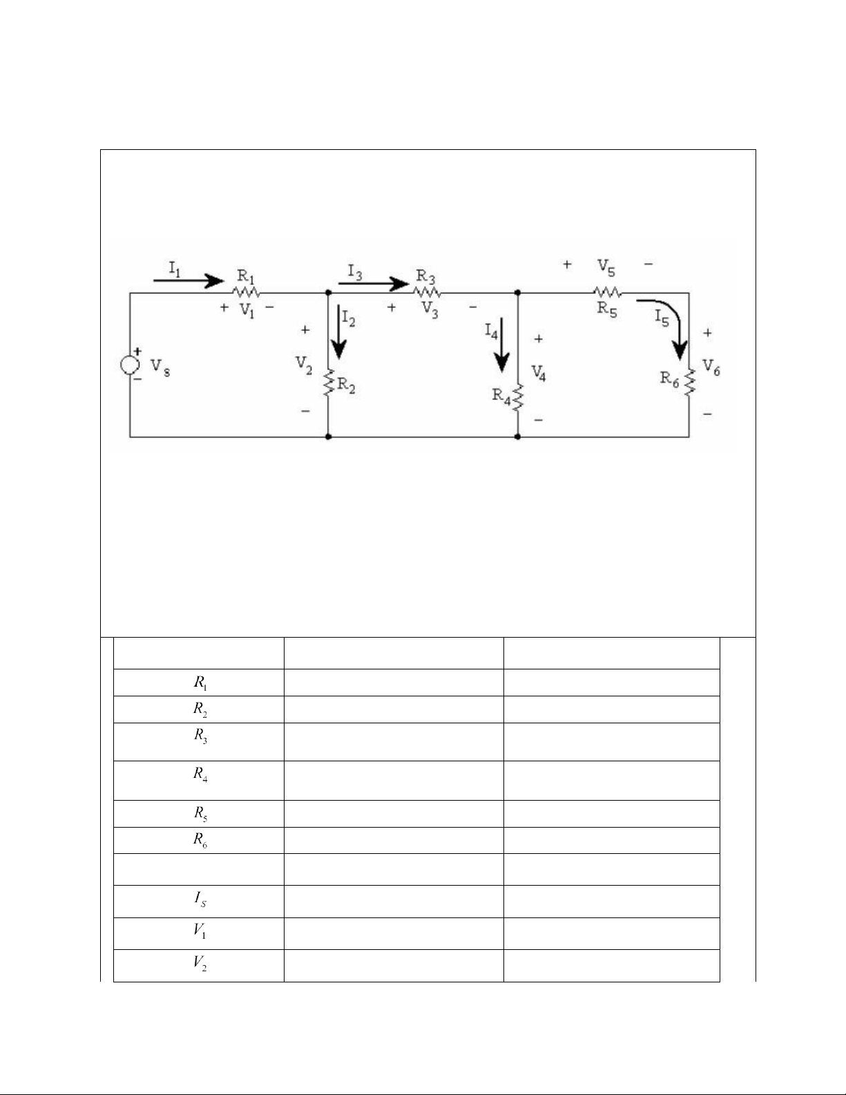
a circuit conforming the circuit below. Make sure you record the actual value of each
resistor used along with the position in which it was used. Figure II-3
Calculate*, simulate and record all the currents and voltages in Circuit 3 setting Vs close to 18 V DC. Vs=Is×Req Table II-3 Color code Nominal Values Brown Black Red Gold 0.9922kOhm Red red red gold 2.1678kOhm Orange orange red gold 3.2752kOhm Orange white red gold 3.834kOhm Yellow violet red gold 4.618kOhm Green blue red gold 5.492kOhm Simulated Values Measured Values lOMoAR cPSD| 58583460 International University Principles of EE I
School of Electrical Engineering EE052IU 8.581V 9.384V 3.715 V 5.671 V
Apply KVL to each loop and KCL to each node. How closely do the voltages and currents
add up to the values calculated? Were Kirchoff's laws verified to within the accuracy of the
meter used in the simulation program? Comment on your obtain results. lOMoAR cPSD| 58583460 International University Principles of EE I
School of Electrical Engineering EE052IU
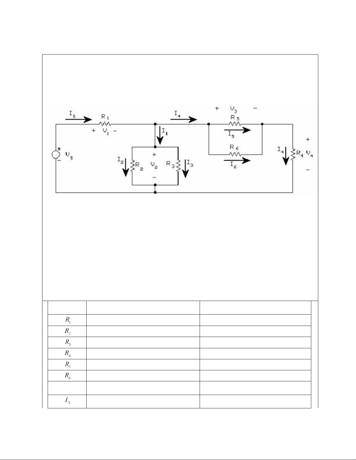
Using the adjustable D.C. power supply and circuit bread board, connect the resistors into
a circuit conforming the circuit below. Make sure you record the actual value of each
resistor used along with the position in which it was used. Figure II-4
Calculate*, measure and record all the currents and voltages in Circuit 4 setting Vs close to 20 V DC Table II-4 Color code Actual value Brown Black Red Gold 0.9922kOhm Red red red gold 2.1678kOhm Orange orange red gold 3.2752kOhm Orange white red gold 3.834kOhm Yellow violet red gold 4.618kOhm Green blue red gold 5.492kOhm Simulated Values Measured Values 7.645V 12.3V lOMoAR cPSD| 58583460 International University Principles of EE I
School of Electrical Engineering EE052IU 6.651V 5.650V 2.5832V lOMoAR cPSD| 58583460 International University Principles of EE I
School of Electrical Engineering EE052IU 3.07 V lOMoAR cPSD| 58583460 International University Principles of EE I
School of Electrical Engineering EE052IU | Principles of EE I
Tài liệu liên quan:
-
Lab Report Template Môn Electrical Engineering | Trường Đại học Quốc tế, Đại học Quốc gia Thành phố Hồ Chí Minh
122 61 -
Lab 7: FET Amplifier Study Guide | Môn Electrical Engineering - Trường Đại học Quốc tế, Đại học Quốc gia Thành phố Hồ Chí Minh
99 50 -
Review Midterm: Differential & Integration Amplifiers Concepts | Môn Electrical Engineering - Trường Đại học Quốc tế, Đại học Quốc gia Thành phố Hồ Chí Minh
108 54 -

Instruction Set Overview: Key Registers and Addressing Modes | Môn Electrical Engineering - Trường Đại học Quốc tế, Đại học Quốc gia Thành phố Hồ Chí Minh
96 48