Project special project (EN) | Tiểu luận môn Công nghệ kĩ thuật Ô tô Trường đại học sư phạm kỹ thuật TP. Hồ Chí Minh
2.1.3 Number of cylinders (i) Compression ratio of an engine is an important parameter for engine performance because it affects many other parameters i = 6; 2.1.4 Compression ratio (ℇ) ℇ= 21.5; 2.1.5 Structural parameters ratio S/D: This is an important structural parameter, affecting the frame size, weight and economic technical features of the internal combustion engine. Tài liệu giúp bạn tham khảo, ôn tập và đạt kết quả cao. Mời bạn đọc đón xem!
Môn: Công nghệ kĩ thuật oto (OTO21) 155 tài liệu
Trường: Trường Đại học Sư phạm Kỹ thuật Thành phố Hồ Chí Minh 4.4 K tài liệu
Tác giả:


Preview text:
HO CHI MINH CITY UNIVERSITY OF TECHNOLOGY AND EDUCATION
FACULTY FOR HIGH QUALITY TRAINING PROJECT SPECIAL PROJECT (EN)
NGUYỄN ANH QUỐC 20145431 Major: AUTOMOTIVE ENGINEERING Advisor: L
Ý VĨNH ĐẠT, PhD. Ho Chi Minh City, May 2023
HO CHI MINH CITY UNIVERSITY OF TECHNOLOGY AND EDUCATION
FACULTY FOR HIGH QUALITY TRAINING PROJECT SPECIAL PROJECT (EN)
NGUYỄN ANH QUỐC 20145431 Major: AUTOMOTIVE ENGINEERING
Advisor: LÝ VĨNH ĐẠT, PhD. Ho Chi Minh City, May 2023 i
THE SOCIALIST REPUBLIC OF VIETNAM
Independence – Freedom– Happiness Ho Chi Minh City, May , 2023 GRADUATION PROJECT ASSIGNMENT
Student name: .................................................................Student ID: .................................
Student name: .................................................................Student ID: .................................
Student name: .................................................................Student ID: .................................
Student name: .................................................................Student ID: .................................
Student name: .................................................................Student ID: .................................
Major: ...............................................................................Class:...........................................
Advisor: .............................................................................Phone number:…………………
Date of assigment:………………………………………..Date of submission:……………. 1. Project
title:…………………………………………………………………………….
2. Initial materials provided by the advisor:……………………………………………...
3. Content of the project:…………………………………………………………………
4. Final product:………………………………………………………………………… CHAIR OF THE PROGRAM ADVISOR (Sign with ful name) (Sign with ful name) ii
THE SOCIALIST REPUBLIC OF VIETNAM
Independence – Freedom– Happiness Ho Chi Minh City, May , 2023
ADVISOR’S EVALUATION SHEET
Student name: ................................................................. Student ID: .................................
Student name: ................................................................. Student ID: .................................
Student name: ................................................................. tudent ID: ..................................
Student name: ................................................................. Student ID: .................................
Student name: ................................................................. Student ID: .................................
Major: ..................................................................................................................................
Project title: ..........................................................................................................................
..............................................................................................................................................
Advisor: ................................................................................................................................ EVALUATION 1. Content of the project:
..............................................................................................................................................
.............................................................................................................................................. 2. Strengths:
..............................................................................................................................................
.............................................................................................................................................. 3. Weaknesses:
..............................................................................................................................................
4. Approval for oral defense? (Approved or denied)
..............................................................................................................................................
5. Overall evaluation: (Excellent, Good, Fair, Poor)
………………………………………
6. Mark:……………….(in words:..............................................................................)
Ho Chi Minh City, month day, year ADVISOR (Sign with ful name) i i
THE SOCIALIST REPUBLIC OF VIETNAM
Independence – Freedom– Happiness Ho Chi Minh City, May , 2023 PRE-DEFENSE EVALUATION SHEET
Student name: .................................................................Student ID: .............................
Student name: .................................................................Student ID: .............................
Student name: .................................................................Student ID: .............................
Student name: .................................................................Student ID: .............................
Student name: .................................................................Student ID: .............................
Major: .....................................................................................................................................
Project title: ............................................................................................................................
Name of Reviewer: ................................................................................................................. EVALUATION
1. Content and workload of the project
.................................................................................................................................................
................................................................................................................................................. 2. Strengths:
.................................................................................................................................................
................................................................................................................................................. 3. Weaknesses:
.................................................................................................................................................
.................................................................................................................................................
4. Approval for oral defense? (Approved or denied)
.................................................................................................................................................
5. Overall evaluation: (Excellent, Good, Fair, Poor)
................................................................................................................................................. 6. Mark:……………….( :
in words ........................................................................................)
Ho Chi Minh City, month day, year REVIEWER (Sign with ful name ) iv
THE SOCIALIST REPUBLIC OF VIETNAM
Independence – Freedom– Happiness Ho Chi Minh City, May, 2023 EVALUATION SHEET OF DEFENSE COMMITTEE MEMBER
Student name: .................................................................Student ID: .................................
Student name: .................................................................Student ID: .................................
Student name: .................................................................Student ID: .................................
Student name: .................................................................Student ID: .................................
Student name: .................................................................Student ID: .................................
Major: ......................................................................................................................................
Project title: ..............................................................................................................................
Name of Defense Committee Member:................................................................................... EVALUATION
1. Content and workload of the project
.................................................................................................................................................
................................................................................................................................................. 2. Strengths:
.................................................................................................................................................
................................................................................................................................................. 3. Weaknesses:
.................................................................................................................................................
.................................................................................................................................................
4. Overall evaluation: (Excellent, Good, Fair, Poor)
.................................................................................................................................................
5. Mark:……………….(in words: ........................................................................................)
Ho Chi Minh City, month day, year COMMITTEE MEMBER (Sign with ful name) v 1. Engine parameters:
Engine: Swirl combustion chamber Stroke, τ: 4
Max Brake Power, Pmax (kW): 97kW RPM: 4800 max power, Compression ratio, ε: 21.5:1
Texture parameters λ = R/L = 0,25 ( choose)
No of cylinder, i: 6 Cylinder inline (1-3-6-5-4-2) 2. Report content
2.1 Thermal calculate and build indicated work diagram in engine. 2.1.1 Design power (Ne) Ne = 97 kW 2.1.2 Design rpm (n) n = 4800 RPM 2.1.3 Number of cylinders (i)
Compression ratio of an engine is an important parameter for engine performance because
it affects many other parameters: i = 6 2.1.4 Compression ratio (ℇ) ℇ= 21.5
2.1.5 Structural parameters ratio S/D:
This is an important structural parameter, affecting the frame size, weight and economic-
technical features of the internal combustion engine. Because of Swirl combustion chamber so 𝑆 = 1 𝐷
2.1.6 Determination of engine speed (vp)
Calculating engine speed is determined by the average speed of piston, (𝑉𝑝): High speed
engine should choose Vp = 9 m/s
2.2 Select heat calculation parameters
2.2.1 Intake air pressure (P0) P0 = 0.1013 MN/𝑚2 1
2.2.2 New intake air temperature (T0)
The South of our country belongs to the tropics, the average temperature of the day can be
chosen as tkk = 29oC for the southern region, so: T o o
0 = (tkk + 273), K = 29 + 273 = 302 ( K)
2.2.3 Intake air pressure before intake valve (Pk)
Non-supercharged four-stroke engine: Pk = P0 = 0.1013 MN/𝑚2
2.2.4 Intake air temperature before intake valve (Tk)
Non-turbocharged four-stroke engine: T o k = T0 = 302 ( K) 2.2.5 End-intake pressure Pa
During the thermal calculation, the final rate of loading pa of a 4-stroke non-turbocharged
engine is usually determined by the empirical formula:
Pa = (0,8÷0,95) Po = 0.9Po= 0.09117 MN/m2
2.2.6 Select residual air pressure Pr
For diesel engines choose: Pr = (0.106 ÷ 0,115) = 0,11 (MPa)
2.2.7 Residual air temperature (Tr)
The value of 𝑇𝑟 can be selected in the following range with four-strokes diesel engine 𝑇𝑟 = 700 ÷ 900oK so choose T o r = 800 K
2.2.8 New intake air temperature rise
For diesel engine ΔT = 10 ÷ 25oC we choose ΔT = 20oC
2.2.9 Choose filling factor 𝜆𝟏
The additional charge factor λ1 represents the relative increase in the volume of the working
gas mixture after filling with the volume occupied by the work gas at the volume Va.
Loading factor selected within the limit λ1 = 1.02 ÷ 1.07. So choose λ1 =1.05
2.2.10 Select the combustion chamber scanning coefficient 𝜆 𝟐
For non-turbocharged engines, we choose 𝝀2= 1
2.2.11 Select the thermophysical correction factor𝝀 : 𝒕
The specific heat correction factor λt depends on the composition of the mixed gas α and
the residual gas temperature Tr.
Because α = 1.4 => choose λt = 1.12
2.2.12 Factor of heat utilization at point Z (𝝃𝒛):
For the diesel engine we choose 𝜉𝑧 = 0.8 2
2.2.13 Factor of heat utilization at point b (𝝃𝒃):
For the diesel engine we choose 𝜉𝑏 = 0.9
2.2.14 Choose the air residue coefficient 𝜶:
For the diesel engine we choose 𝛼 = 1.4
2.2.15 Choose the coefficient o ffilling the work graph ng 𝝋d:
The work graph fill factor φd evaluates the loss in area of the actual work graph compared to
the calculated work graph Because of Swirl combustion chamber so we choose 𝜑d = (0,92 ÷ 0,96) = 0,92
2.2.16 Turbocharger ratio λp
It is the ratio between the pressure of the gas mixture in the cylinder at the end of combustion
and the compression process 𝜆𝑝 = 𝑃𝑧/𝑃𝑐
The value of λ is usually in the following range:
Gasoline engine: : λ = 3,00 ÷ 4,00
Diesel engine: λ = 1,35 ÷ 2,40 => Choose λp = 2 2.3 Heat calculation
Calculating heat to determine the parameters of the theoretical cycle and the economic -
technical criteria of the engine. The engine work indicator graph is built on the basis of thermal
calculation results and is the basic data for the next steps of dynamic calculation and engine design calculation. 2.3.1 Intake process 2.3.1.1 Intake factor (ɳv) 1 1 𝑇 𝑝 𝑃 𝑚 ɳ 𝑘 𝑎 𝑟 𝑣 = 𝜀 − 1 . 𝑇
[𝜀. λ1 − λ𝑡. λ2. ( ) ] 𝑘 + ∆𝑇 . 𝑝𝑘 𝑃𝑎
m: As the average multivariable index of air, choose m = (1,45÷1,5) = 1,5 1 1 302 0,09117 0,11 1,5 ɳ𝑣 = ] = 0,87727
21,5 − 1 . 302 + 20 . 0,1013 [21,5.1,05 − 1,12.1. (0,09117)
=> Satisfy high speed diesel engine ηv = 0.75÷0.90 3 2.3.1.2
Residual gas coefficient (γr)
𝛾𝑟 = 𝜆2 . 𝑃𝑟 . 𝑇𝑜 = 1 . 0,11 . 302 = 0,02279
(𝜀−1).𝜂𝑣 𝑃𝑜 𝑇𝑟 (21,5−1).0,87727 0,1013 800
=> Satisfying non-turbocharged diesel engine. 2.3.1.3
Temperature at the end of charging Ta 𝑚−1 1,5−1 (𝑇 𝑚 0,09117 1,5
𝑘 + ∆𝑇) + λ𝑡. γ𝑟. 𝑇𝑟. (𝑃𝑎 ) (302 + 20) + 1,12.0,02279.80 . 0 ( 𝑇 𝑃𝑟 0,11 ) 𝑎 = 1 + γ = 𝑟 1 + 0,02279 = 334(° 𝐾)
=> Satisfied non-turbocharged diesel engine T o a= 310-360 C 2.3.2 Compression process 2.3.2.1
Average mol heat ratio of new intake gas:
𝑚𝑐𝑣 = 𝑎𝑣 + 𝑏 . T = 19,806 + 0,00419 . T 2 2
𝑎𝑣 = 19,806; 𝑏𝑣 = 0,00419 2.3.2.2
Average mol ratio of products of combustion:
When α ≥ 1 is calculated for diesel engines according to the following formula: 𝑚𝑐 1,634 1 184,36 𝑣′ = (19,806 + 2 ) + 2 (427,38 + α ) . 10−5. T
𝑅𝑒𝑝𝑙𝑎𝑐𝑒 𝛼 = 1,4 𝑤𝑒 𝑟𝑒𝑐𝑖𝑒𝑣𝑒 𝑎′′ ′ −3 𝑣 = 20,62 ; 3 𝑏 ′𝑣 = 5,59. 10 2.3.2.3
The average isovolumetric molar ratio of the compressed circular gas mixture: ′ −3 𝑚𝑐
𝑚𝑐𝑣+γ𝑟.𝑚𝑐𝑣 , +2,
. −3𝑇)+0,02279.(20,623+2,795.10 𝑇) 𝑣′ = = 𝑎′ 𝑇 = (19 806 09510 1+ γ 𝑣 + 𝑏′ 𝑟 2 1+0,02279 => 𝑎′ ′ −3 𝑣 = 19,824 ; 2 𝑏 𝑣 = 4,2212. 10 4 2.3.2.4
The average multivariable compression ratio n1:
The average multivariate compression index n1 was determined by solving the equation: 8,314 8,314 𝑛1 − 1 = = 𝑎′ . −3 𝑣 + 𝑏′𝑣
2 . 𝑇𝑎. (𝜀𝑛1−1 + 1) 19,8242 + 4,2212 10 2 . 334 . (21,5𝑛1−1 + 1)
𝑛1 = 1,37 (satisfy 4-stroke diesel engine n1= 1,29 ÷ 1,40) 2.3.2.5 Compression process pressure 𝑃 𝑛 1,37
𝑐 = 𝑃𝑎. 𝜀 1 = 0,09117. 21,5 = 6,1 (𝑀𝑃𝑎) 2.3.2.6
Temperature at the last phase of compression process 𝑇 o
𝑐 = 𝑇𝑎. ℇ n1−1 = 1039 K
Satisfy 4-stroke diesel engine 450-1050 oK 2.3.3 Combustion process: 2.3.3.1
Theoretically mass of air need to burn 1kg of fuel Mo:
M0 = 1 ( 𝐶 + 𝐻 − 𝑂 ) = 0,435 𝑘𝑚𝑜𝑙 7 . 𝑘𝑘 21 12 4 32 2.3.3.2
Amount of new intake air actually load into cylinder M1
M1 = α.M0 = 0,4357.1.4 = 0,60998 (kmol kk/kg.nl) 2.3.3.3 M
The amount of flowing product 2 :
Because α ≥ 1 so 𝑀2 = 𝑂+ 𝐻 + 𝛼. 𝑀 32 4 0 = 0,641605 2.3.3.4
Molecular transformation coefficient when theoretical β0
β0 =M2 = 0,641605 = 1,052 (𝑘𝑚𝑜𝑙 𝑆𝐶𝑉 𝑛𝑙) M1 0,60998 𝑘𝑔 2.3.3.5
Molecular transformation coefficient when theoretical β
In fact, due to the influence of residual gas in the cylinder from the previous cycle, the actual
gas molecular change coefficient β is determined by the following formula: β= 1 + β0−1 = 1+ 1,05 −1 2 = 1,05 (satisfy α=1,4) 1+𝛾r 1+0,03254 5 2.3.3.6
Molecular coefficient o change when at the point f z β 05
z = 1+β0−1 . ℇz = 1 + 1, −1 . 0,8 = 1,04345 1+𝛾r ℇb 1+0,02279 0,9 2.3.3.7 Heat loss due t in o complete melting
Because of diesel engine, we have : 𝛼 ≥ 1 so ∆QH = 0 (KJ/kg.nl) 2.3.3.8
The average isothermal molar heat of each substance at z β ). 𝑚𝑐
′+ ( 1− Xz). 𝑚𝑐 𝑚 𝑐′ 0.(Xz + 𝛾rβ0 𝑣 𝑣 𝑣𝑧 = 𝛽0.(Xz + 𝛾r (1) )+ ( 1− X β0 z) where: Xz= ξz = 0,8 ; β ξ 0 = 1,052 b 0,9 and 𝑚𝑐 ′ −3
𝑣 = 19,806 + 0,00419. 𝑇 𝑎𝑛𝑑 𝑚𝑐 = 19,8242 + 4,2212. 10 𝑇 2 𝑣
so replacing them to equation (1) we have 1,052. (0,8 . −3𝑇) + ( 1 − 0,8 𝑚𝑐 ′ 0,9 + 0,02279 1,052 ) . (19,8242 + 4,2212 10 0,9) . (19,806 + 0,00419 2 T) 𝑣𝑧 = 1,052. (0,8 0,9 + 0,02279 1,052 ) + ( 1 − 0,8 0,9) => 𝑚 𝑐 ′ ′ 𝑣𝑧
= 𝑎𝑣𝑧+ 𝑏𝑣𝑧′ 𝑇 , + 2, . −3𝑇 2 𝑧 = 19 822 109 10 𝑧 2.3.3.9
Temparature at end of combustion Tz
𝜉𝑧.(𝑄𝐻) + (𝑚𝑐′ + 8,314λ 314 𝑀 𝑣𝑐
𝑝)𝑇𝑐 = β𝑧. (𝑚𝑐𝑣𝑧" + 8, ). 𝑇𝑧 1.(1+𝛾𝑟) We have: 𝑚𝑐′ −3
𝑣𝑐 = 19,8242 + 2,1106. 10 . 1039 = 22,02 𝑚𝑐′ -3
𝑣𝑧=19,822+2,109.10 . 𝑇𝑧
⇔ 1,04345. (19,822 + 2,019. 10−3𝑇𝑧 + 8,314). 𝑇𝑧 − 94691 = 0
Solving the equation to choose a positive root we get Tz = 2685 (⁰K) 6
2.3.3.10 Pressure at end-combustion Pz For diesel engine:
𝑃𝑧 = λ𝑝. 𝑃𝑐 = 2.6,1 = 12,2 (𝑀𝑃𝑎)
2.3.4 Expansion process calculation
2.3.4.1 Before expansion ratio
Diesel engine: 𝜌 = β𝑧.𝑇𝑧 = 1,04345 . 2685 = 1,35 λ𝑝 𝑇𝑐 2 1039 2.3.4.2 After expansion ratio
Diesel engine: 𝛿 = 𝜀= 21,5 = 15,9259 𝜌 1,35
2.3.4.3 Determine the mean multivariable expansion index
(𝜉𝑏 −𝜉𝑧).𝑄𝐻 ′ ′ 8,314 𝑀
= 𝛽. 𝑚𝑐𝑣𝑏. 𝑇𝑏 − 𝛽𝑧. 𝑚𝑐𝑣𝑧 .𝑇𝑧 +
. (𝛽𝑧. 𝑇𝑧 − 𝛽. 𝑇𝑏) 1 𝑛2 − 1
At temperatures from 1200-2600°K, the difference of the ratio is not very large so we cansee: ′ 𝑎 ′ 𝑣𝑏
= 𝑎𝑣𝑧;𝑏𝑏 = 𝑏𝑧 và 𝛽 = 𝛽𝑧 : 8,314 𝑛2 − 1 =
(𝜉𝑏 − 𝜉𝑧).𝑄𝐻 𝑀 ′ + 𝑏𝑧′
1. (1 + 𝛾𝑟). 𝛽. (𝑇𝑧 − 𝑇𝑏) + 𝑎𝑣𝑧 2 . (𝑇𝑧 + 𝑇𝑏)
Where: 𝑇𝑏 is the calorific value at point b and is determined by the formula: 𝑇 𝑇 𝑧 𝑏 = 𝛿𝑛2−1 We have : 𝑚𝑐′ −3 ′
𝑣𝑧= 19,8242 + 2,1106. 10 . 2685 = 𝑎𝑣𝑧 + 𝑏′𝑣𝑧 . 𝑇 2 𝑧
⇒ 𝑛2 = 1,25 (𝑠𝑎𝑡𝑖𝑓𝑦 1 1,15 − 1,2 ) 6
2.3.4.4 Thermal at end of expansion process 𝑻 𝒃 For Diesel engine we have: 𝑇 2685 𝑇 𝑧
𝑏 = 𝛿𝑛2−1 = 15,92591,25 −1 1 = 1320 (𝐾) 7
2.3.4.5 Pressure at end of expansion process 𝑷𝒃 𝑃 12,2 𝑃 𝑧 𝑏 = 𝛿𝑛 = 2
15,92591,251 = 0,38(𝑀𝑃𝑎)
2.3.4.6 Check residual gas temperature 𝑻𝒓: 𝑇 𝑇 𝑏 𝑟 = = 873(° 𝐾) √ 3 𝑃𝑏 𝑃𝑟 2.3.4.7 Error of residual gas Δ𝑇𝑟
𝑇 = 8,36% < 10% (𝑆𝑎𝑡𝑖𝑠𝑓𝑦) 𝑟
2.4 Calculation of cycle characteristics
2.4.1 Calculated average indication pressure 𝑃′𝑖 = 𝑃𝑐 . (λ
. (1 − 1 ) − 1 . (1 − 1 )) = 1,34567 𝑀𝑃𝑎 𝜀−1 𝑝. (ρ − 1) + ρλ𝑝β 𝑛2−1 δ 𝑛2−1 𝑛1−1 𝜀𝑛1−1
2.4.2 Actual average indicated pressure (𝐏𝐢) 𝑝 ′
𝑖 = 𝜑𝑑. 𝑝𝑖 = 0,92.1,34567 = 1,238
2.4.3 Mechanical loss pressure 𝐏𝐦
Pm = 𝑎 + 𝑏. Vp + (𝑃r − Pa)
Because Swirl combustion chamber so choose a=0,089 and b = 0,01315 => Pm= 0,22618
2.4.4 Determine mean effective pressure 𝐏𝐞
𝑃𝑒 = 𝑃𝑖 − 𝑃𝑚 = 1,238 − 0,22618 = 1,01182 2.4.5 Motor performance 𝜂 𝑃 𝑃 0,22618 𝜂 𝑒 𝑒 𝑚 𝑀 = 𝜂 = = 1 − = 1 − 𝑖 𝑃𝑖 𝑃𝑖 1,238 = 0,8173
=> Suitable for non-turbocharged diesel engine. 2.4.6 Indicator performance 𝑀 0,60998 .1,238. 302 𝜂 1. 𝑃𝑖. 𝑇𝑘 𝑖 = 8,314. 𝑄 = 8,314. = 0,5 𝐻. 𝑃𝑘. 𝜂𝑣 42530 . 0,1013 . 0 8 , 7727
=> Suitable for non-turbocharged diesel engine. 8 2.4.7 Useful performance
𝜂𝑒 = 𝜂𝑖.𝜂𝑀 = 0,817 .0,5 3 = 0,41
=> Suitable for non-turbocharged diesel engine.
2.4.8 Calculate the indicated fuel consumption rate 𝒈𝒊
𝑔𝑖 = 3600 = 3600 = 0,17 kg/kWh 𝑄𝐻.𝜂𝑖 42530 . 0,5
Satisfied four-stroke non-turbocharged diesel engine
2.4.9 Calculate useful fuel consumption𝒈 : 𝒆
𝑔𝑒 = 3600 = 0,21 Kg /kWh 𝑄𝐻.𝜂𝑒
=> Satisfied four-stroke non-turbocharged diesel engine.
2.4.10 Calculate the structural parameters of the engine:
- Calculate the volume of work 𝑉 Calculate the volume of work: ℎ 30. 𝜏. N 30.4.97 𝑉 e
ℎ = 𝑛𝑒.𝑝𝑒.𝑖 = 4800.6.1,01182 = 0.399 = 0,4 𝑑𝑚3, (𝑙𝑖𝑡𝑒𝑟) In there:
𝜏 : Number of cycles of the engine
𝑖 : Number of cylinders of the engine
𝑛𝑒: Number of revolutions of the engine a design power t 𝑁𝑒 design e – ngine power, kW
𝑝𝑒 : Average effective pressure, MN/ 𝑚2 - Combustion chamber volume: 𝑉 0,4 𝑉 ℎ
𝑐 = 𝜀 − 1 = 21,5 − 1 = 0,02 𝑑𝑚3, (𝑙𝑖𝑡𝑒𝑟) - Total volume:
𝑉𝑎 = 𝑉𝑐 + 𝑉ℎ = 0,02 + 0,4 = 0,42 𝑑𝑚3, (𝑙𝑖𝑡𝑒𝑟) - Diameter of piston: 3 4. 𝑉 𝐷 = ℎ √ = 0,8 𝑑𝑚 𝜋. (𝑆𝐷) - Piston stroke: 𝑆
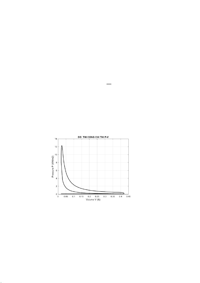
𝑆 = (𝐷)𝐷 = 1.0,8 = 0,8 𝑑𝑚 9 3. Curves 3.1 P - V figure
Identify the special points of the graph P-V
Grade a: the end point of the suction stroke Pa = 0,091 17 (MPa); V 3 a =0,42(dm ); T o a = 334 K
Grade c: end point of compression stroke Vc = 0,02(dm 3); Pc = 6,1 (MPa); T o c = 1039 K ;
Grade z: the end point of the fire journey V 3
z = pVc (diesel) = 1,35 .0,02 = 0,027 (dm ); Pz = 12,2 (MPa) ; T o z = 2685 K ;
Grade b: the end point of the expansion journey V 3 b = Va = 0,42 (dm ); Pb = 0,38(MPa); T o b = 1320 K
Grade r: the end point of the exhaust journey: Vr = Vc = 0,02 (dm 3); Pr = 0,11; Tr = 800 oK ;
Contruct the compression curve
During compression, the gas in the cylinder is compressed with the average multivariable index 𝑛1 from the equation: P n1 n a. Va = Pxn. Vxn1 = const
In there: 𝑃𝑎, 𝑉𝑎 are the pressure and volume of gas at point a
𝑃𝑥𝑛, 𝑉𝑥𝑛 are pressure and volume at any point on the compression curve V n1 P a xn = Pa. ( V ) xn 10
By letting the values Vxn go from Va to Vc, we can determine the values in turn 𝑃𝑥𝑛. Construct the expansion curve
During the expansion process, the combustible gas is expanded according to the multivariable inde n2. Similarly we have: P n n z. V 2 z = Pxg. V 2 xg = const V n2 P z xg = Pz. ( V ) xg
Pxg, Vxg are the pressure and volume at any point on the expansion curve. Vxg g from o
Vz to Vb We can determine the values, respectively Pxg.
Connecting the above points together by commands in MATLAB, we get the PV indicator graph as follows: 11 3.2 Kinetics and dynamics 3.2.1 Air Force
From the indicator work graph, draw a graph of the gas force Pkt based on the
pressure values available in the indicator work graph P - V and draw it according to the crankshaft rotation angle
Intake process: = 3°, 180°] pkt = pa
Compression process: = 180°, 360° = 180°, 345° V n1 p a kt = pa. ( V ) c′
Power process: go from the end point of the combustion process on the indicative work diagram to
𝛼 = [360°, 540° − 𝛽1] = [360°, 488 ]° V n2 p z′ kt = pz′ . ( V ) b′
Exhaust process: α = [540°, 720°] pkt = pr
The correction segments of the pkt graph are similar to those shown on the P-V
indicator work graph, but instead of V, the gas force graph will be adjusted according to 3.2.2
Mass of crank mechanism connecting rod –
* Mass of piston group (mass of reciprocating parts)
Based on Table 4.1( giáo trình hướng dẫn đồ t trong trang 75) and the án Động cơ đố cylinder diameter we choose: m (aluminum alloy piston) . p′ = 18 (g/cm2)
* Mass of crankshaft (rotating parts)
Based on Table 4.1( giáo trình hướng dẫn đồ án Động cơ đốt trong trang 75) and the cylinder diameter we choose: m k′ = 18 (g/cm2) (cast iron crankshaft). 12
* Mass of connecting rod group
Based on Table 4.1( giáo trình hướng dẫn đồ án Động cơ đốt trong trang 75) and the cylinder diameter we choose: m t′ = 28 (g/cm2) According to the formula: 1 2
ma = 3.mt′ = 9,33 𝑎𝑛𝑑 mb = 3.mt′ = 18,67
Mass of reciprocating movement of crankshaft connecting rod: –
mt = mp′ + ma = 18 + 9,33 = 27,33
Rotational mass of connecting rod crankshaft mechanism:
mr = mk′ + mB = 18 + 18,67 = 36,67
3.2.3 The inertia force of the translational mass
The inertial (straight) force of the translational moving mass
Pj = −mt. R. ω2. (cos(α) + λ. cos(2α)) (MN/m2), where α follows the same
process as for the pkt gas force.
The inertial force (centrifugal force) of the rotating mass Pk Pk = −mr. R. ω2(MN/m2)
The total force p1: is the combined force of the gas force and the inertial force calculated by the formula: P1 = Pkt + Pj Specially : Angle Beta:
𝛽 = arcsin (𝜆. 𝑠𝑖𝑛𝑎)
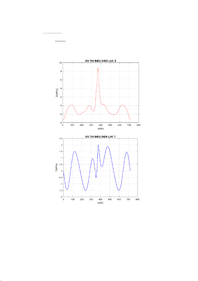
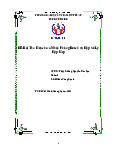
The force acting along the center of the connecting rod Ptt . The horizontal force N pushing
the piston against the cylinder wall are the component forces of PΣ. N = PΣtan (β) Tangent force T = PΣ. sin (α+β) cos (β) 13 Normal force Z = PΣ. cos (α+β) cos (β)
Using MATLAB, we can plot the forces as follows: 14
Tài liệu liên quan:
-
Bài thu hoạch cá nhân phòng Bosch và hộ số ly hợp kép | Nghành công nghệ kỹ thuật ô tô Trường đại học sư phạm kỹ thuật TP. Hồ Chí Minh
334 167 -
Động cơ tỉ nén biến thiên | Tiểu luận môn Công nghệ kĩ thuật ô tô Trường đại học sư phạm kỹ thuật TP. Hồ Chí Minh
530 265 -

Báo cáo thực tập tốt nghiệp: Công ty Cổ Phần Ôtô Kim Thanh | Báo cáo môn Công nghệ kĩ thuật ô tô Trường đại học sư phạm kỹ thuật TP. Hồ Chí Minh
1.2 K 576 -
Báo cáo thực tập hệ thống truyền động servo | Báo cáo môn Công nghễ kĩ thuật ô tô Trường đại học sư phạm kỹ thuật TP. Hồ Chí Minh
592 296 -

Hệ thống truyền lực trên ô tô (powertrain system) | Bài giảng môn Công nghễ kĩ thuật ô tô Trường đại học sư phạm kỹ thuật TP. Hồ Chí Minh
890 445