Braking Force Distribution Strategy for HEV Based on Braking Strength | Tài liệu môn thí nghiệm vật lý 1 Trường Đại học sư phạm kỹ thuật TP Hồ Chí Minh
Abstract—The possibility of recovering vehicle kinetic energy is one inherent advantage of hybrid electric vehicle (HEV). Due to the introduction of electric regenerative braking, the
structure, design and control of a hybrid electric vehicle is quite different from the pure mechanical braking of conventional vehicles. In this paper, the decelerations of the vehicle in typical urban driving cycles and the influences of, Tài liệu giúp bạn tham khảo, ôn tập và đạt kết quả cao. Mời bạn đọc đón xem!
Môn: Thí nghiệm vật lý 1 (PHYS111202) 90 tài liệu
Trường: Trường Đại học Sư phạm Kỹ thuật Thành phố Hồ Chí Minh 4.4 K tài liệu
Tác giả:
Preview text:
2010 International Conference on Measuring Technology and Mechatronics Automation
Braking Force Distribution Strategy for HEV Based on Braking Strength
Liang Chu, Mingli Shang, Yong Fang, Jianhua Guo, Feikun Zhou
State Key Laboratory of Automobile Dynamic Simulation, Jilin University, Changchun, 130025, P.R. China shangmingli@foxmail.com
Abstract—The possibility of recovering vehicle kinetic energy
maximizing the recovery of braking energy, using the
is one inherent advantage of hybrid electric vehicle (HEV).
braking strength sub-design method to design the
Due to the introduction of electric regenerative braking, the distribution strategy.
structure, design and control of a hybrid electric vehicle is
quite different from the pure mechanical braking of II. STRUCTURE AN D PRINCIPLE
conventional vehicles. In this paper, the decelerations of the
In this paper, the hybrid electric vehicle is equipped with
vehicle in typical urban driving cycles and the influences of
ESP system and motor, so the design of the braking system
regenerative braking have been investigated. The results
is different from the conventional vehicles.
provide strong supports to the design of the braking force
distribution strategy for the hybrid electric vehicle. This paper A. Structure
designs a deceleration sensitive braking force distribution
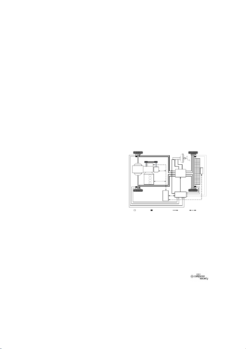
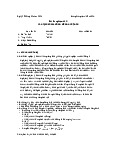
Figure 1 show the structure of the HEV this paper
strategy to distribute the desired total braking force to the
studied. The HEV is a front wheel driven vehicle. Motor is
front and rear axles. This strategy can recovery more braking
installed in the automatic transmission input axle. This
energy and can keep the vehicle more stable while the vehicle
structure increases the motor torque which acting on the
is braked. The proposed distribution strategy is tested through
the simulation, and the simulation results show the
wheels. The HEV which is studied is equipped with ESP.
distribution strategy is effective.
Compared with the original vehicle, the HEV braking
system only increases the vacuum pump and the pedal travel
Keywords-HEV; Braking force distribution; regenerative
simulator and the pressure sensors. Rest parts are unchanged.
braking; hybrid braking system; motor braking
This effective uses the existing systems and saves cost. I. INTRODUCTION
Almost half of the energy is dissipated in the brakes TC T U C
while a vehicle drives in heavy traffic [1]. Therefore, y C r AM A U T T mo m t o o t r o U
recovering braking energy is an effective approach for M tte a C B HC H U C
improving the energy efficiency of hybrid electric vehicle B [2]-[4].
The research and development activities on hybrid
electric vehicles have been mainly concentrated on the
drivetrain architectures, parametric design, drivetrain
control, modeling and simulation etc.[5]-[7] However, le ic U ES E P S _ P E _ C E U C h C
relatively less effort has been made on the research of the h e H V
braking system for hybrid electric vehicles, and publications
on this topic are much less than those for powertrain technology development. Speed sensor Pressure sensor Signal CAN bus
In braking system design for the HEV, two basic
concerns are: (1) properly applying braking force on front
Figure 1. Schematic structure of the hybrid vehicle
and rear axles to quickly reduce the vehicle speed, and
meanwhile, maintaining the vehicle traveling direction stable B. Basic principle
and controllable, (2) recovering the braking energy as much
The drivers’ braking force demand is calculated from the
as possible in order to improving the energy utilization
pedal stroke which is measured by the stroke sensor. Then efficiency [8].
under the braking force distribution strategy, we can
In this paper, the HEV is equipped with ESP system, and
calculate the motor braking force and hydraulic braking
the regenerative braking system of the HEV is utilized the
force. Via CAN communication, the demand of motor torque
ESP valve. This paper designs the regenerative braking
is sent to motor controller to achieve to recovery the braking
system structure of the HEV, and designs the braking force
force. Hydraulic braking force is achieved by controlling the
distribution strategy. By analyzing the driving cycles, as well
ESP valves. As the ESP valves have the fine adjustment
as the performance of the motor, designs the braking force
function, therefore, the HEV braking system is able to meet
distribution strategy. Fully taking into account the
the drivers’ dynamic braking demand needs.
contradiction between the drivers’ driving demand and
978-0-7695-3962-1/10 $26.00 © 2010 IEEE 759 DOI 10.1109/ICMTMA.2010.344
In hydraulic pressure control process, the vacuum pump 300 peak power torque
provides the required hydraulic pressure. The control of the rated torque
vacuum pump is based on the maximum front and rear axle peak power braking torque 200 rated braking torque
hydraulic pressure, this can reduce the ESP valves operation )
times and extend the ESP valves life. .m 100 (N
In the regenerative braking control process, the e u
regenerative braking strategy is in the vehicle controller, 0 rq
vehicle controller, ESP controller and motor controller via r to to
CAN to communicate each other and coordinate each system -100 o m to work well. -200
III. INFLUENCING FACTORS OF REGENERATIVE BRAKING -300 FORCE 0 1000 2000 3000 4000 5000 6000 7000 8000
The braking force distribution strategy is one most motor speed(r/min)
important thing of the braking system design of the hybrid
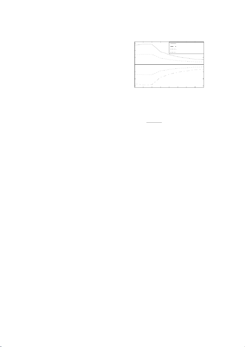
Figure 2. Characteristic of the PMSM
electric vehicle. Beginning the design the braking force
distribution, we need consider the influence factors of
The torque characteristic of the permanent magnet
regenerative braking. In this paper, we consider the
synchronous motor can be expressed as [5]:
performance of the motor and the battery. T ⎧ (ω ≤ ω ) max m b
A. Desired Braking Force ⎪ T = ⎨ P (5) m 9550
According to the definition of the braking strength [8], max (ω > ω ) ⎪ m b
the desired total braking force can be obtained. ⎩ ωm F = mzg (1) B
C. The Maximum Motor Braking Torque Determined by
Where, m is the vehicle mass in kg, z is the braking the Battery
strength, FB is the total braking force acting on the vehicle.
During the regenerative braking, the electric current
In this paper, by actually measures the braking pedal
which is generated by the motor is charged to the battery, so
travel, the relationship between the brake pedal travel and
the performance of the battery influences the maximum
the braking strength can be calculated by: motor braking force. z = k S (2) z
The relationship between the power, electric current and Where, k
the resistance of the battery can be expressed as:
z is the braking strength coefficient, S is the braking pedal travel. P = (E − IR )I (6) b soc soc
Adopted Equ.(1) and Equ.(2), the relationship between Where, P
the desired braking force and the brake pedal travel can be
b is the power of the battery in W, ESOC is the
EMF of the battery which is changing with the SOC of the obtained:
battery in V, I is the electric current in A, and RSOC is the F = k S B b (3)
resistance which is changing with the SOC of the battery in Ω k = mgk . b z (4)
Therefore, the maximum braking power of the motor Where, k must be met:
b is the braking force coefficient. P ≤ P B. Motor Braking Force (7) M max b
During the regenerative braking of the hybrid electric
Where, PMmax is the maximum braking power of the
vehicle, the motor is the energy recovery device. Therefore, motor.
the braking performance of the motor is an important
In order to protect the battery and to extend the life of the
influence factor for the regenerative braking performance of
battery, while the SOC of the battery is larger than a the vehicle.
threshold, the battery is not charged, that means the
In this paper, the motor of the HEV is a permanent
regenerative braking system of the HEV is stopped and the
magnet synchronous motor (PMSM). Permanent magnet
total desired braking force is applied to the hydraulic
synchronous motor has advantages of high efficiency and
braking. Therefore, the maximum braking power of the
wide speed range, so it has been widely used in the hybrid
motor which is determined by the battery can be expressed electric vehicles. as:
When the motor speed is below the base speed of the ⎧P (SOC ≤ SOC ) b max
motor, the motor works at constant torque, and when the P = ⎨ (8) M max
motor speed is above the base speed of the motor, the motor ⎩0 (SOC > SOC ) max
works at constant power. Figure2 shows the characteristic of
the permanent magnet synchronous motor which is used in the HEV that is been studied. 760
IV. REGENERATIVE BRAKING FORCE 0.3 DISTRIBUTION STRATEGY 0.2
After investigating the performance of the motor and the th g
battery, we should analysis the driving cycles. We can use 0.1 n
the results to design the braking force distribution of the tre 0 s
front and rear axles. Then, considering the stability of the g in
vehicle, we can design the braking force distribution of the k -0.1 motor and hydraulic braking. ra b -0.2
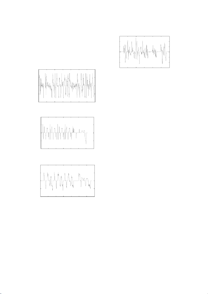
A. Driving Cycles Analysis 0.2 0 100 200 300 400 500 600 time(s)
Figure 6. The braking strength of NYCC 0.1 th g n
The investigation of the braking characteristics of the tre
driving cycle is conducted based on some standard urban 0 s g
driving cycles. The typical driving cycles that are used in in k
this paper are: UDDS, EUDC, 1015, and NYCC. Based on -0.1 bra
the four driving cycles, the braking strength of each driving
cycle can be calculated which is shown in Figure 3-Figure 6.
Through analysis Figure 3 to Figure 6, one conclusion -0.20 200 400 600 800 1000 1200 1400
can be obtained: all of the four driving cycles’ braking time(s)
strength are small and less than 0.15, only the braking
strength of the NYCC driving cycle is little large, but most
Figure 3. The braking strength of UDDS
of its’ braking strength is also less than 0.15. This also 0.2
implied that the vehicle is in a small braking state on the
whole while the vehicle is in urban driving condition. So, in
this paper, the most working range of the motor braking is 0.1 th
that the braking strength is less than 0.15. The vehicle is g n
stable because the vehicle is in linear region when a small 0
braking strength is applied to the vehicle. stre g in
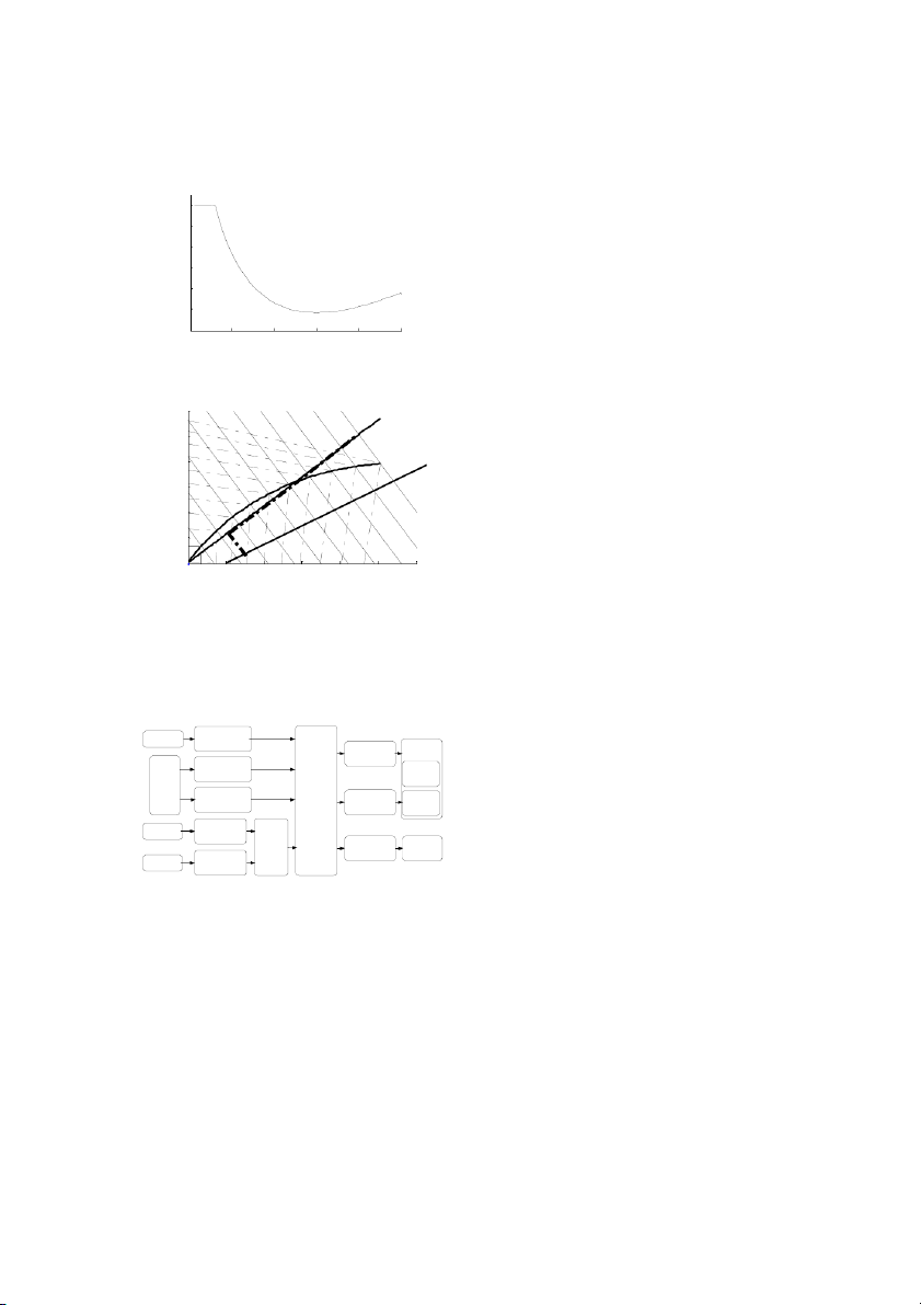
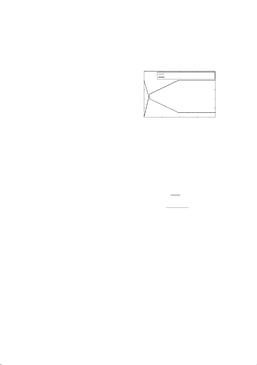
B. Front and rear axle braking force distribution curve k ra-0.1 b
In order to guarantee the braking distance and stability of
the hybrid vehicle to meet the ECE braking regulation [3], it -0.2
is necessary to calculate the relationship between the 0 200 400 600 800 1000 1200 1400
permission braking force distribution coefficient and the time(s)
braking strength. Figure 7 shows the curve between the
Figure 4. The braking strength of EUDC
permission braking force distribution coefficient and the
braking strength of the studied hybrid electric vehicle.
In order to maximize the recovery of the braking energy, 0.2
it is necessary to distribute braking force to front axle as
more as possible under the premising of the vehicle stability. 0.1 th
Based on the above considerations, this paper determines g n
the braking force distribution based on braking strength. tre 0
Figure 8 shows the braking force distribution curve of this s g paper. in k
The braking strength is divided into four grades: z ≤ ra-0.1 b
0.15, 0.15 < z ≤ 0.3, 0.3 < z ≤ 0.6, and z > 0.6. In order to
comply with the requirement of the ECE regulations and -0.2
reduce the operations times of the ESP valves, this paper 0 100 200 300 400 500 600 700
distribute 80% total braking force to front axle while the time(s)
braking strength is 0.15< z ≤0.3. And taking the vehicle
Figure 5. The braking strength of 1015
stability into account, this paper distributes the total braking
force according to the original braking force distribution
coefficient of the vehicle while the braking strength is 0.3< z
≤0.6. In order to prevent the influence of the fluctuation of
the motor torque to the vehicle at large braking closes the 761
regenerative braking function of the motor while the braking
braking force and the motor braking force. Thus, the process strength is z > 0.6
of the regenerative braking control can be completed. t n
Taking into account the inertia and torque fluctuation of ie 1
the motor, turns off the regenerative braking system while ffic e o
the vehicle is under ABS or ESP control. 0.98 c
This paper uses the deceleration of the vehicle to design n 0.96 tio
the braking force distribution strategy of the HEV. The u
strategy is a deceleration sensitive strategy (DS). Detailed 0.94 trib is
control strategies are as follows: d 0.92 e (1) While z ≤ 0.15 rc 0.9
The braking force distribution strategy distributes all of fo g
the desired braking force to the front axle. If at this time, the in 0.88 k
torque of the motor can meet the total desired braking force, 0.1 0.2 0.3 0.4 0.5 0.6 ra braking strength b
then, the motor supplies the total desired braking force. If
this moment, the torque of the motor can not able to meet the
Figure 7. The relationship between the braking force distribution
coefficient and the braking strength
total desired braking force, then, the motor supplies the
current maximum braking force of the motor, the inadequate
desired braking force is distributed to front hydraulic braking 6000 )
and rear hydraulic braking according to the original braking (N β
distribution curve of the vehicle. This can reduce the e 5000 rc
operation times of the ESP valves. The maximum braking fo I 4000 g
force of the motor is calculated from the maximum power of in k
the motor which considered the influence of the battery. The 3000 ra 80%
above process can be expressed as follows: b D le ⎧ x F ( F ≤ F ) 2000 b b M max F = ⎨ r a (9) m a ⎩F ( F > F ) 1000 re C M max b M max A B ⎧0 (F ≤ F ) 0 b M max 0 2000 4000 6000 8000 10000 12000 F = ⎨ (10) Hf front axle braking force(N) ⎩(F − F )β ( F > F ) b M max b M max ⎧
Figure 8. The braking force distribution curve of the HEV 0 ( F ≤ F ) b M max F = ⎨ (11) Hr ⎩( F − F
)(1 − β ) ( F > F ) b M max b M max
C. Braking force distribution strategy
Where, Fb is the total desired braking force in N, Fm is
After determining the front and rear axle braking force
the braking force of the motor in N, FMmax is the current
distribution curve, it can be used to design the braking force
maximum braking force of the motor in N, FHf is the front strategy of the vehicle.
axle hydraulic braking force in N, FHr is the rear axle
Figure 9 shows the overall regenerative braking control
hydraulic braking force in N, β is the original braking
block diagram of the hybrid electric vehicle.
distribution coefficient of the vehicle. Wheel speed ABS/TCS/ESP Front axle Braking (2) While 0.15 < z ≤ 0.3 hydraulic ECU
The braking force distribution strategy distributes 80% Deceleration braking force
desired braking force to front axle in order to recovery Braking calculate ESP ECU pedal
braking energy as more as possible. While braking strength RBS stoke Desired Rear axle distribution Pump
is in this range, the tire of the vehicle is in linear range, so braking force hydraulic strategy ECU braking force
the vehicle is stable, and at this moment, the recovering Motor Motor Motor maximum
braking energy is more important than the stability of the speed braking braking force Motor braking Motor
vehicle. If at this moment, the torque of the motor can meet force Battery force ECU Battery can
the distributed braking force of the front axle, then the motor maximum infomation supply braking forcr
supplies the total front axle braking force. If at this moment,
the torque of the motor can not able to meet the distributed
Figure 9. The regenerative braking control block diagram of the vehicle
braking force of the front axle, then, the motor supplies the
Firstly, using the braking pedal stroke to calculate the
current maximum braking force of the motor, the inadequate
desired braking force, then integrating the current
front axle braking force is distributed to front hydraulic
information of the maximum braking force of the motor and
braking and rear hydraulic braking according to the original
the maximum allowable braking force of the battery, after
braking distribution curve of the vehicle. The above process
these, the braking force distribution strategy can be used to can be expressed as follows:
calculate the current front axle braking force, rear axle 762 ⎧F (F ⎪ ≤ F )
And the simulation results are compared with the simulation f f M max F = ⎨ (12)
results of the ADVISOR braking force distribution strategy. m F ⎪ (F > F ) ⎩
Prior to comparing analysis, it is necessary to introduce the M max f M max
braking force distribution strategy of the ADVISOR. Figure ⎧0 (F ⎪ ≤ F )
10 shows the braking force distribution strategy of the f M max F = ⎨ (13) ADVISOR. Hf ⎪(F − F )β (F > F ) ⎩ f M max f M max t 1 n ⎧⎪0.2F (F ≤ F ) ie
front axle friction braking distribution coefficient b f Mmax F = ⎨
motor braking distribution coefficient (14) ffic Hr e 0.8 ⎪(F −F
)(1−β) +0.2F (F > F ) ⎩ o f Mmax b f Mmax c n F = 0.8 F (15) tio 0.6 f b u Where, F trib
f is the front axle braking force in N. is (3) While 0.3 < z ≤ 0.6 0.4 d e
The braking force distribution strategy distributes the rc
desired braking force to front axle and rear axle according to fo g 0.2
the original braking distribution coefficient of the vehicle. in k
Thus, the braking stability performance of the vehicle can be ra b 0
ensured while the vehicle is in medium braking strength. If 0 50 100 150 200
at this moment, the torque of the motor can meet the vehicle speed(Km/h)
distributed braking force of the front axle, then the motor
Figure 10. The braking force distribution strategy of the ADVISOR
supplies the total front axle braking force. If at this moment,
the torque of the motor can not able to meet the distributed
The braking force distribution strategy of the ADVISOR
braking force of the front axle, then, the motor supplies the
is speed-sensitive type. As the vehicle speed increasing, the
current maximum of the motor, the inadequate front axle
braking force distribution coefficient of the motor increases.
braking force is distributed to front hydraulic braking. The
The biggest problem of this distribution strategy is it not
above process can be expressed as follows:
considers the impact of the vehicle deceleration. The strategy ⎧
of this paper is deceleration sensitive type (DS). ⎪F ( F ≤ F ) f f M max F = ⎨
In order to effectively evaluate the effect of the (16) m ⎪F ( F > F ) ⎩
regenerative braking, this paper selects four evaluation M max f M max
indicators as follows: the SOC of the battery; the fuel ⎧0 (F ≤ F ) ⎪
consumption of the vehicle; the recovery efficiency of the f M max F = ⎨ (17)
braking energy; the efficiency of the overall vehicle system. Hf ⎪F − F ( F > F ) ⎩ f M max f M max
The definition of the recovery efficiency of the braking
energy and the efficiency of the overall vehicle system can
F = (1− β )F (18) Hr b be expressed as follows: F = F β (19) E f b regen η = (23) (4) While z > 0.6 regen Ebrake
While the braking strength of the vehicle is in this range,
the vehicle is in heavy braking status, therefore, the E + E aero roll η = (24)
important thing of this moment is the stability of the vehicle vehicle E − E fuel charg e
not the recovering the braking energy. As the time of the Where, E
heavy braking is short and the recovering energy of the
regen is the recovery braking energy, Ebrake is the
total braking energy of the driving cycle. E
motor is small, so, the regenerative braking system is closed, aero is the
and the desired braking force is distributed to front and rear
aerodynamic drag energy, Eroll is the rolling resistance
hydraulic braking according to the original braking
energy, Efuel is the fuel consume energy, Echarge is the charged
distribution coefficient of the vehicle. The above process can energy of the battery. be expressed as follows:
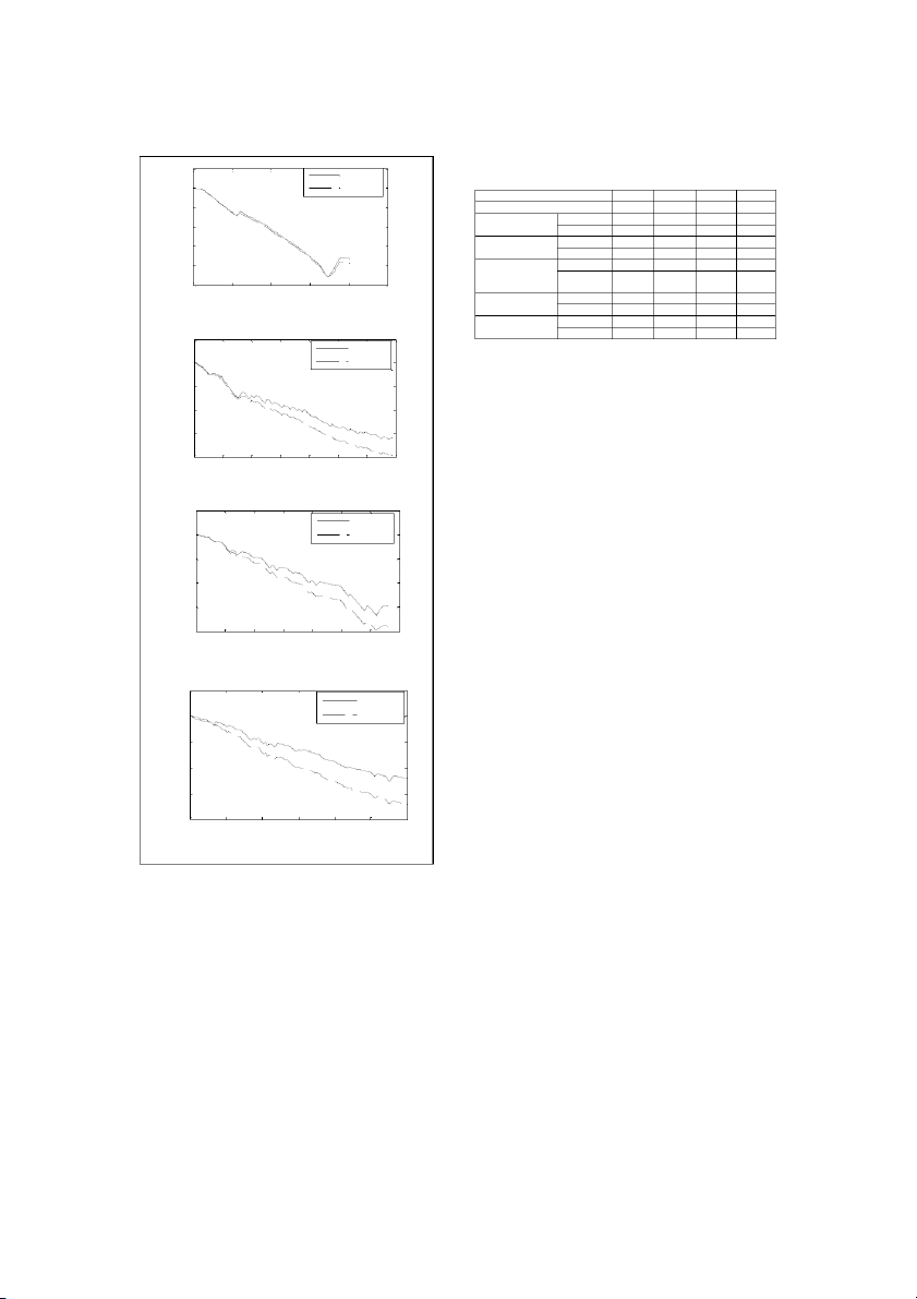
This paper selects four kinds of driving cycles: EUDC,
UDDS, 1015, NYCC to analysis the braking force F = 0 (20) m
distribution strategy of this paper.
F = (1− β )F (21)
Figure 11 shows the SOC status of the four driving cycles. Hr b
Where, the DS in the figure is the deceleration sensitive F = F β (22)
braking force distribution strategy of this paper. The figures Hf b
show that the SOC of the deceleration sensitive is higher V. SIMULATION RESULTS
than the SOC of the ADVISOR. The results indicate that the
deceleration sensitive strategy can recover more energy than
In this paper, the ADVISOR2002 software is used to
the speed sensitive strategy of the ADVISOR.
simulate and analysis the braking force distribution strategy. 763 TABLE I.
THE RESULTS OF THE EVALUATION OF DRIVING 0.705 CYLES DS 0.7 ADVISOR Driving cycle UDDS EUDC 1015 NYCC 0.695 Traveling distance, Km 12 7 4.2 1.9 C Fuel consume ADVISOR 5 4.3 5.6 11.1 0.69 O Per cycle, L/Km DS 4.9 4.2 5.5 11 S braking energy, ADVISOR 1856 542 660 614 0.685 KJ DS 1925 531 658 670 0.68 Regenerative ADVISOR 1017 166 367 302 braking energy, DS 1640 457 658 568 0.675 KJ 0 100 200 300 400 500 Regenerative ADVISOR 0.55 0.31 0.56 0.49 time(s) braking efficient DS 0.85 0.86 1 0.85 (a) EUDC Overall vehicle ADVISOR 0.112 0.209 0.087 0.033 system efficient DS 0.115 0.244 0.09 0.035 0.71 DS 0.7 ADVISOR VI. CONCLUSION 0.69
This paper studied the braking strength of four typical C O
driving cycles. Then, the paper studied the performance of S 0.68
the motor and the battery. And some important conclusion
can be used to design the braking force distribution strategy. 0.67
The braking force distribution strategy of this paper is 0.66
deceleration sensitive strategy. This strategy considers the 0 200 400 600 800 1000 1200 1400
braking strength of the typical driving, and then the braking time(s)
strength is divided into four grades to design the front and (b) UDDS
rear axles braking force. Then, considering the influence of 0.705
the battery, the motor braking force can be calculated. And DS
the front and rear axle hydraulic braking force can be 0.7 ADVISOR
calculated also. The simulation results show the braking
force distribution strategy can recover more braking energy. 0.695 C O S ACKNOWLEDGEMENT 0.69
This work is supported by the key project of the science 0.685
and technology research of the eduction department
(NO01059): the regenerative braking control system of the 0.68 0 100 200 300 400 500 600 700
hybrid electric vehicle key technologies. time(s) REFERENCES (c) 1015
[1] Yimin Gao, Liping Chen, and Mehrdad, “Investigation of the 0.705
Effectiveness of Regenerative Braking for EV and HEV,” SAE paper, DS 1999-01-2910. 0.7 ADVISOR
[2] Yimin Gao, Liang Chu, and Mehrdad, “Design and Control
Principles of Hybrid Braking System for EV, HEV and FCV,”IEEE 0.695
Transaction on vehicular Technology, Vol.54, NO.2, Sep.2008. C O
[3] R.Apter, M.Prathaler, “Regeneration of Power in Hybrid Vehicles” S 0.69
IEEE Transaction on vehicular Technology, Vol.35, NO.3, Sep.2002.
[4] A.M.Walker, M.U.Lamperth and S.Wilkins, “On Friction Braking 0.685
Demand with Regenerative Braking,”SAE paper, 2002-01-2581.
[5] Ahu E.Hartavi, Ismail M.C.Uygan, and Volkan Sezer, “Electric 0.68
Regenerative Power Assisted Brake Algorithm for Front and Rear 0 100 200 300 400 500 600
Wheel Drive Parallel Hybrid Electric Commercial Van,” SAE paper, time(s) 2008-01-2606. (d) NYCC
[6] Nobuyoshi Mutoh, and Hiromichi, “Electrical Braking Control
Figure 11. The SOC status of the four driving cycles
Methods for Electric vehicles with Independently Driven Front and
Rear Wheel Structure,”Industrial Electronis, IEEE transaction on, Vol.54, Issue 2. April 2007.
Table 1 shows the detail calculation results of the four
[7] M.Ehsani, Y.Gao, S.E.gay and A.Emadi, Modern Electric, Hybrid,
evaluation indicators in four driving cycles. The results
and Fuel Cell Vehicles: Fundamentals, Thory and Design, CRC
indicate that the strategy of this paper can recover more Press,2005.
braking energy than the strategy of the ADVISOR. So the
[8] J.Y.Wong, Theory of Ground Vehicles. John Wiley and Sons, New
effective of the deceleration braking force distribution York, 1978 strategy is certificated. 764
Tài liệu liên quan:
-
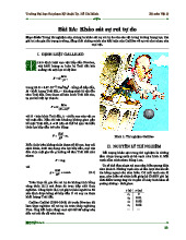
Giáo trình Khảo sát sự rơi tự do môn Vật lý | Trường Đại học Sư phạm Kỹ thuật Thành phố Hồ Chí Minh
45 23 -

Bài thí nghiệm số 2 trường đại học
51 26 -
Mau bao cao mon TNVL 1 trường đại học
43 22 -
Bài thí nghiệm 2 và 3: Ma sát trục bánh xe - Dao động con lắc môn Thí nghiệm Vật lý | Trường Đại học Sư phạm Kỹ thuật Thành phố Hồ Chí Minh
45 23 -
Bài thí nghiệm số 1: Xác định khối lượng riêng chất rắn | Báo cáo môn thí nghiệm Vật lý Trường đại học sư phạm kỹ thuật TP. Hồ Chí Minh
0.9 K 472