Chapter 6 WCDMA môn Thu phát vô tuyến | Học viện Công Nghệ Bưu Chính Viễn Thông
Table 6.1 lists the parameters of WCDMA. WCDMA has two modes characterized by the duplex method: FDD (frequency division duplex) and TDD (time division duplex), for operating with paired and unpaired bands, respectively [1]. Tài liệu được sưu tầm, biên soạn dưới dạng file PDF gồm 36 trang, giúp các bạn học tốt, ôn tập hiệu quả, đạt kết quả cao trong các bài thi, bài kiểm tra sắp tới. Mời bạn đón xem!
Môn: Thu phát vô tuyến (TEL1416) 10 tài liệu
Trường: Học viện Công Nghệ Bưu Chính Viễn Thông 1.8 K tài liệu
Tác giả:


Preview text:
lOMoAR cPSD| 58977565 Chapter 6 WCDMA Chapter 6 6.1 INTRODUCTION
This chapter presents the WCDMA air interface, referred also as UMTS terrestrial radio
access (UTRA), developed by the third-generation partnership project (3GPP). 3GPP
has the goal to harmonize and standardize in detail the similar proposals from ETSI, ARIB, TTC, TTA, and T1.
Table 6.1 lists the parameters of WCDMA. WCDMA has two modes
characterized by the duplex method: FDD (frequency division duplex) and TDD (time
division duplex), for operating with paired and unpaired bands, respectively [1]. The
TDD mode is described in Chapter 7.
The chip rate of the system is 3.84 Mcps. The frame length is 10 ms and each
frame is divided into 15 slots (2560 chip/slot at the chip rate 3.84 Mcps). Spreading
factors range from 256 to 4 in the uplink and from 512 to 4 in the downlink. Thus, the
respective modulation symbol rates vary from 960 k symbols/s to 15 k symbols/s (7.5 k
symbols/s) for FDD uplink. For separating channels from the same source, orthogonal
variable spreading factor (OVSF) channelization codes are used. In the downlink, Gold
codes with a 10-ms period (38400 chips at 3.84 Mcps) are used to separate different
cells, with the actual code itself length 218-1 chips. In the uplink, Gold codes with a
10ms period, or alternatively short codes with a 256-chip period, are used to separate the different users.
For the channel coding three options are supported: convolutional coding, turbo
coding, or no channel coding. Channel coding selection is indicated by upper layers. Bit
interleaving is used to randomize transmission errors. The modulation scheme is QPSK.
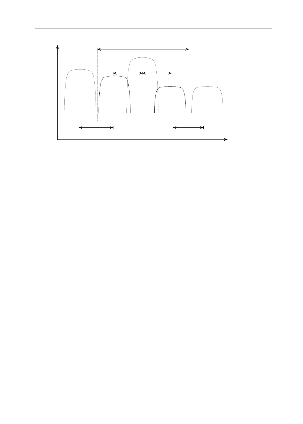
The carrier spacing has a raster of 200 kHz and can vary from 4.2 to 5.4 MHz.
The different carrier spacings can be used to obtain suitable adjacent channel protections
depending on the interference scenario. Figure 6.1 shows an example for the operator
bandwidth of 15 MHz with three cell layers. Larger carrier spacing can be applied
between operators than within one operator’s band in order to avoid interoperator
interference. Interfrequency measurements and handovers are supported by 171
WCDMA to utilize several cell layers and carriers.
This chapter is organized as follows. WCDMA specification structure is given
in Section 6.2. Protocol structure and logical and transport channels are described in
Section 6.3. Physical channels, spreading, multirate schemes (variable data rates), lOMoAR cPSD| 58977565 WCDMA 172
packet data, and handover are discussed in Sections 6.4−6.8. Section 6.9 describes the
future evolution of the WCDMA covering release 2000 standards and beyond. 6.2 WCDMA SPECIFICATIONS
The air interface description in the following is based on the 3GPP wideband CDMA
specifications as listed in Table 6.2. The physical layer is specified in TS25 series of 3GPP specifications. Table 6.1 Parameters of WCDMA Channel bandwidth 5 MHz Duplex mode FDD and TDD Downlink RF channel structure Direct spread Chip rate 3.84 Mbps Frame length 10 ms Spreading modulation Balanced QPSK (downlink) Dual-channel QPSK(uplink) Complex spreading circuit Data modulation QPSK (downlink) BPSK (uplink) Channel coding Convolutional and turbo codes Coherent detection
User dedicated time multiplexed pilot (downlink
and uplink), common pilot in the downlink
Channel multiplexing in downlink
Data and control channels time multiplexed
Channel multiplexing in uplink
Control and pilot channel time multiplexed
I&Q multiplexing for data and control channel Multirate
Variable spreading and multicode Spreading factors
4–256 (uplink), 4–512 (uplink) Power control
Open and fast closed loop (1.6 kHz) Spreading (downlink)
OVSF sequences for channel separation
Gold sequences 218-1 for cell and user separation (truncated cycle 10 ms) Spreading (uplink)
OVSF sequences, Gold sequence 241 for user
separation (different time shifts in I and Q channel, truncated cycle 10 ms) Handover Soft handover Interfrequency handover lOMoAR cPSD| 58977565 WCDMA 173 Power Operatorband15MHz 3 celllayers AnotherUMTS operator 4.2-5.0 MHz 4.2-5.0 MHz AnotherUMTS operator 5.0-5.4 MHz 5.0-5.4 MHz Frequency
Figure 6.1 Frequency utilization with WCDMA. 6.3 PROTOCOL ARCHITECTURE
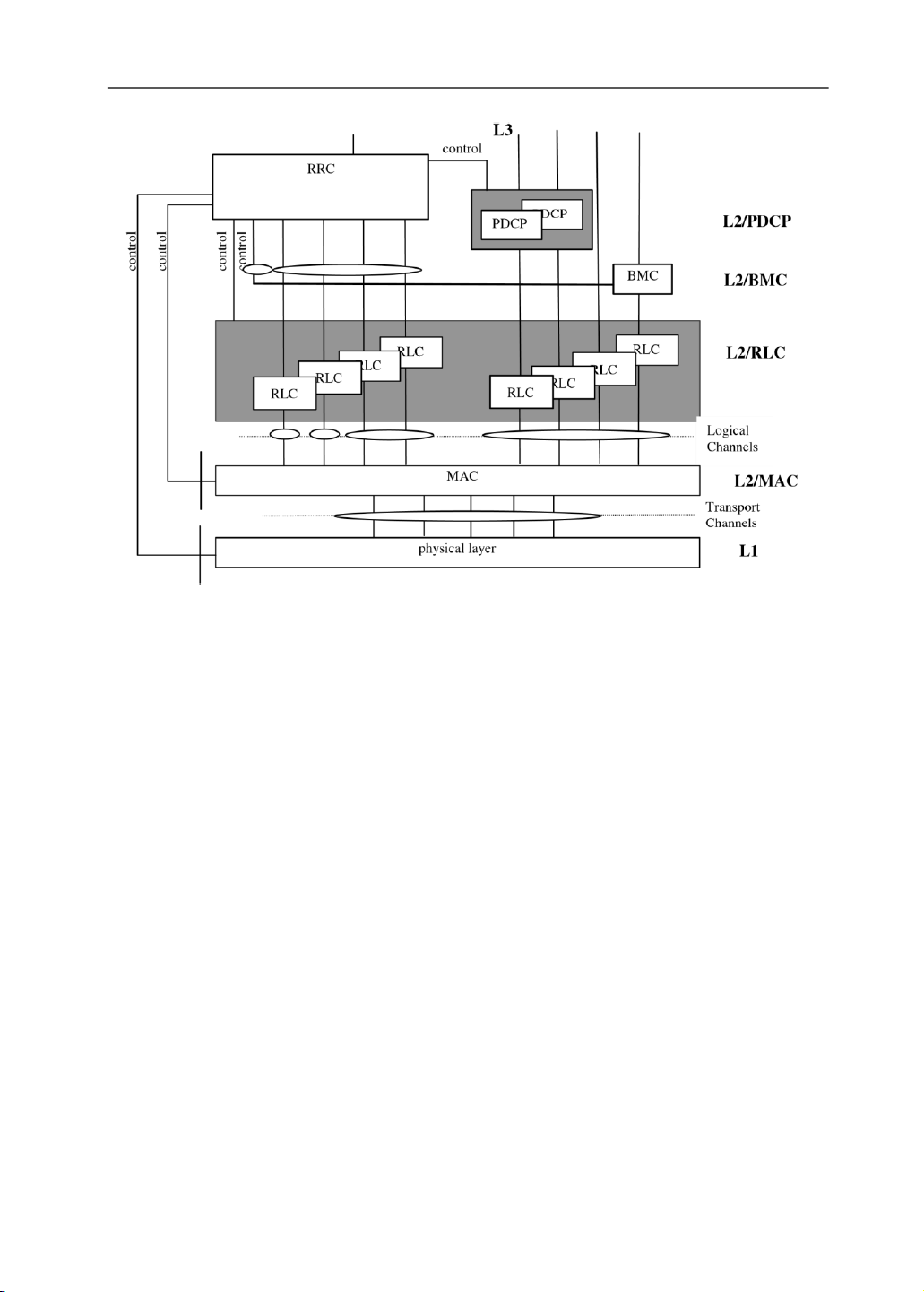
Figure 6.2 shows the air interface protocol architecture. The protocol architecture is
similar to the current ITU-R protocol architecture, ITU-R M.1035. The air interface is
layered into three protocol layers:
• The physical layer (layer 1, L1); • The data link layer (layer 2, L2);
• Network layer (layer 3, L3).
The physical layer interfaces the medium access control (MAC) sublayer of
layer 2 and the radio resource control (RRC) layer of layer 3. The physical layer offers
different transport channels to MAC. A transport channel is characterized by how the
information is transferred over the radio interface. Transport channels are channel coded
and then mapped to the physical channels specified in the physical layer. MAC offers
different logical channels to the radio link control (RLC) sublayer of layer 2. A logical
channel is characterized by the type of information transferred.
Layer 2 is split into following sublayers: MAC, RLC, packet data convergence
protocol (PDCP) and broadcast/multicast control (BMC). Layer 3 and RLC are divided
into control and user planes. PDCP and BMC exist in the user plane only. In the control
plane, layer 3 is partitioned into sublayers where the lowest sublayer, denoted as RRC,
interfaces with layer 2. The RLC sublayer provides ARQ functionality closely coupled
with the radio transmission technique used. Table 6.2 3GPP RAN Specifications lOMoAR cPSD| 58977565 WCDMA 174 Specification Name Scope number TS
Physical layer – general Describes the contents of the layer 1 documents (TS 25.201 description
25.200 series); where to find information; a general description of layer 1 TS Physical channels and
Establishes the characteristics of the layer-1 transport 25.211 mapping of transport
channels and physical channels in the FDD mode, and channels onto physical specifies: channels (FDD) • transport channels •
physical channels and their structure •
relative timing between different physical channels
in the same link, and relative timing between uplink and downlink; •
mapping of transport channels onto the physical channels. TS Multiplexing and
Describes multiplexing, channel coding, and interleaving 25.212 channel coding (FDD)
in the FDD mode and specifies: •
coding and multiplexing of transport channels; • channel coding alternatives; •
coding for layer 1 control information; • different interleavers; • rate matching; •
physical channel segmentation and mapping. TS Spreading and Establishes the characteristics of 25.213 modulation (FDD) the spreading and modulation in the FDD mode, and specifies: • spreading •
generation of channelization and scrambling codes; •
generation of random access preamble codes; •
generation of synchronization codes; • modulation. TS Physical layer
Establishes the characteristics of the physical layer 25.214 procedures
procedures in the FDD mode, and specifies: • cell search (FDD) procedures; • power control procedures; • random access procedure. TS Physical layer
Establishes the characteristics of the physical layer 25.215 measurements (FDD)
measurements in the FDD mode, and specifies: •
the measurements performed by layer 1; •
reporting of measurements to higher layers and network; •
handover measurements and idle-mode measurements. lOMoAR cPSD| 58977565 WCDMA 175
Figure 6.2 Air interface protocol architecture. 6.3.1 Logical Channels
The MAC layer provides data transfer services on logical channels. A set of logical
channel types is defined for different kinds of data transfer services as offered by MAC.
Each logical channel type is defined by the type of information that is transferred.
Logical channel types are depicted in Figure 6.3. Logical channels are classified into two groups:
• Control channels for the transfer of control plane information (Table 6.3)
• Traffic channels for the transfer of user plane information (Table 6.4). lOMoAR cPSD| 58977565 WCDMA 176 Control channel (CCH)
Broadcast control c h annel (BCCH) Paging control channel (PCCH)
Dedicated control channel (DCCH) Common control channel (CCCH)
Shared channel control channel (SHCCH)
ODMA dedicated control channel (ODCCH)
ODMA common control channel (OCCCH) Traffic channel (TCH)
Dedicated t raffic channel (DTCH)
ODMA dedicated traffic channel (ODTCH) Common traffic channel (CTCH)
Figure 6.3 Logical channel structure. Table 6.3 Logical Control Channels
Broadcast control channel (BCCH) Downlink channel for broadcasting system control information. Paging control channel (PCCH)
Downlink channel that transfers paging information and is used when: •
Network does not know the location cell of the mobile station; •
The mobile station is in the cell connected state (utilizing sleep mode procedures). Common control channel (CCCH)
Bidirectional channel that transfers control information
between network and mobile stations. This channel is used: •
By the mobile stations having no RRC connection with the network; •
By the mobile stations using common transport channels
when accessing a new cell after cell reselection.
Dedicated control channel (DCCH)
Point-to-point bidirectional channel that transmits dedicated
control information between a mobile station and the network.
This channel is established through RRC connection setup procedure. ODMA common control channel
Bidirectional channel for transmitting control information (OCCCH) between mobile stations. lOMoAR cPSD| 58977565 WCDMA 177
ODMA dedicated control channel
Point-to-point bidirectional channel that transmits dedicated (ODCCH)
control information between mobile stations. This channel is
established through RRC connection setup procedure. Table 6.4 Traffic Channels
Dedicated traffic channel (DTCH)
Point-to-point channel, dedicated to one mobile
station, for the transfer of user information. A
DTCH can exist in both uplink and downlink.
ODMA dedicated traffic channel (ODTCH)
Point-to-point channel, dedicated to one mobile
station, for the transfer of user information
between mobile stations. An ODTCH exists in
relay link. A point-to-multipoint unidirectional
channel for transfer of dedicated user information
for all or a group of specified mobile stations. 6.3.2 Transport Channels
A transport channel is defined by how and with what characteristics data is transferred
over the air interface. There exist two types of transport channels: • Dedicated channels;
• Common channels, listed in Table 6.5.
There is one dedicated transport channel, the dedicated channel (DCH), which
is a downlink or uplink transport channel. The DCH is transmitted over the entire cell
or over only a part of the cell using beam-forming antennas. The DCH is characterized
by the possibility of fast rate change (every 10 ms), fast power control, and inherent
addressing of mobile stations. 6.3.2.1
Mapping Between Logical Channels and Transport Channels
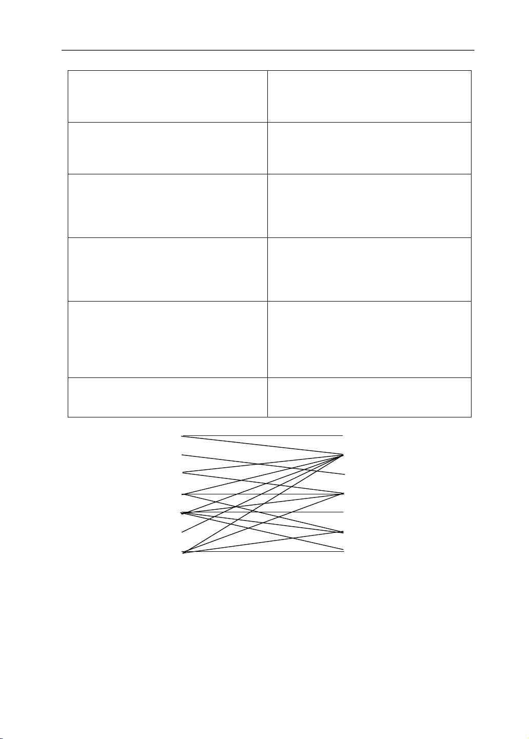
Figure 6.4 shows the mapping between logical and transport channels. The following connections exist:
• BCCH is connected to BCH and may also be connected to FACH. • PCCH is connected to PCH.
• CCCH is connected to RACH and FACH.
• SHCCH is connected to RACH and USCH/FACH and DSCH.
• DTCH can be connected to either RACH and FACH, to RACH and DSCH,
to DCH and DSCH, to a DCH, a CPCH (FDD only).
• CTCH is connected to FACH.
• DCCH can be connected to either RACH and FACH, to RACH and DSCH,
to DCH and DSCH, to a DCH, a CPCH to FAUSCH, CPCH. Table 6.5 Common Transport Channels lOMoAR cPSD| 58977565 WCDMA 178 Broadcast channel (BCH)
Downlink transport channel that is used to
broadcast system- and cell-specific information.
The BCH is always transmitted over the entire cell with a low fixed bit rate. Forward access channel (FACH)
Downlink transport channel. The FACH is
transmitted over the entire cell or over only a part
of the cell using beam-forming antennas. The FACH uses slow power control. Paging channel (PCH)
Downlink transport channel. The PCH is always
transmitted over the entire cell. The transmission
of the PCH is associated with the transmission of
a physical layer signal, the paging indicator, to
support efficient sleep mode procedures. Random access channel (RACH)
Uplink transport channel. The RACH is always
received from the entire cell. The RACH is
characterized by a limited size data field, a
collision risk and by the use of open loop power control. Common packet channel (CPCH)
Uplink transport channel. The CPCH is a
contention-based random access channel used for
transmission of bursty data traffic. CPCH is
associated with a dedicated channel on the
downlink, which provides power control for the uplink CPCH.
Downlink shared channel (DSCH)
Downlink transport channel shared by several
mobile stations The DSCH is associated with a DCH. Logical channels Transport channels BCCH BCH PCCH FACH CCCH PCH SHCCH RACH DTCH CPCH CTCH DSCH DCCH DCH
Figure 6.4 Mapping between logical and transport channels. lOMoAR cPSD| 58977565 WCDMA 179 6.4 PHYSICAL CHANNELS
The transport channels are channel coded and matched to the data rate offered by
physical channels. Thereafter, the transport channels are mapped on the physical
channels. Physical channels consist of radio frames and time slots. The length of a radio
frame is 10 ms and one frame consists of 15 time slots. A time slot is a unit, which
consists of fields containing bits. The number of bits per time slot depends on the
physical channel. Depending on the symbol rate of the physical channel, the
configuration of radio frames or time slots varies. The basic physical resource is the
code/frequency plane. In addition, on the uplink, different information streams may be
transmitted on the I and Q branch. Consequently, a physical channel corresponds to a
specific carrier frequency, code, and, on the uplink, relative phase (0 or p/2). In Section
6.4.1, the different physical channels and their structure are presented. 6.4.1
Uplink Physical Channels
There are two uplink dedicated physical and two common physical channels:
• The uplink dedicated physical data channel (uplink DPDCH) and the uplink
dedicated physical control channel (uplink DPCCH);
• The physical random access channel (PRACH) and physical common packet channel (PCPCH).
The uplink DPDCH is used to carry dedicated data generated at layer 2 and
above (i.e., the dedicated transport channel (DCH)). There may be zero, one, or several
uplink DPDCHs on each layer 1 connection. The uplink DPCCH is used to carry control
information generated at layer 1. Control information consists of known pilot bits to
support channel estimation for coherent detection, transmit power-control (TPC)
commands, feedback information (FBI), and an optional transport-format combination
indicator (TFCI). The transport-format combination indicator informs the receiver about
the instantaneous parameters of the different transport channels multiplexed on the
uplink DPDCH, and corresponds to the data transmitted in the same frame. For each
layer 1 connection there is only one uplink DPCCH.
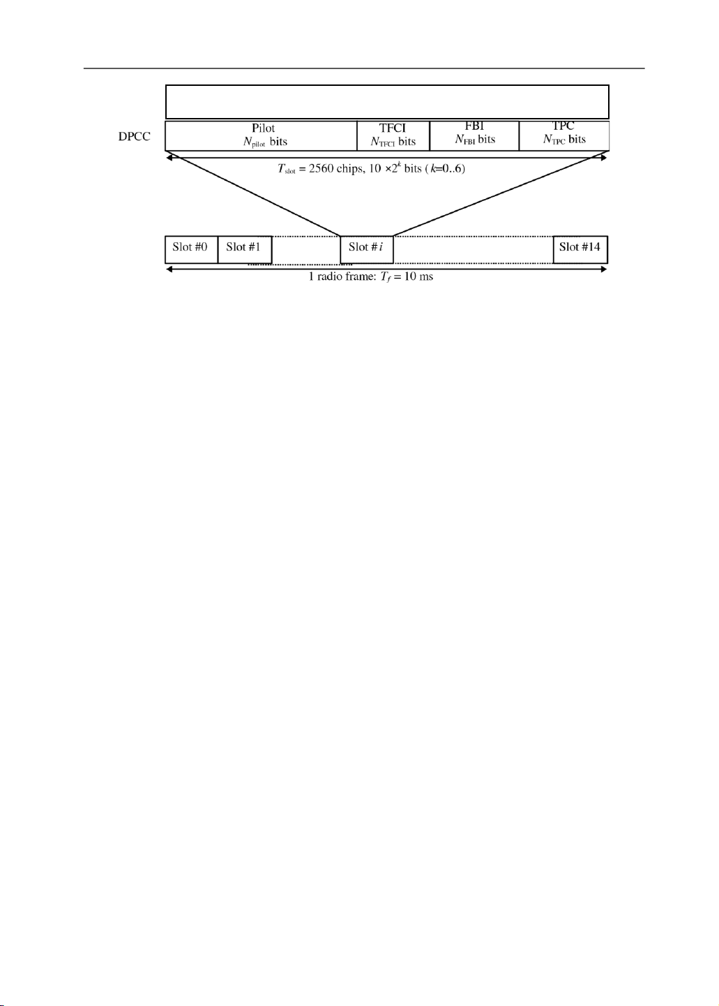
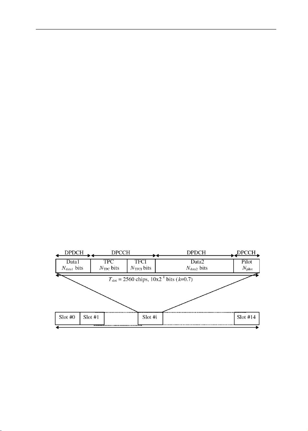
Figure 6.5 shows the principle frame structure of the uplink dedicated physical
channels. Each frame of length 10 ms is split into 15 slots, each of length Tslot = 2560
chips, corresponding to one power-control period.
The parameter k in Figure 6.5 determines the number of bits per uplink
DPDCH/DPCCH slot. It is related to the spreading factor (SF) of the physical channel
as SF = 256/2k. The DPDCH spreading factor may thus range from 256 down to 4. An
uplink DPDCH and uplink DPCCH on the same layer 1 connection generally are of
different rates and thus have different spreading factors. lOMoAR cPSD| 58977565 WCDMA 180 Data DPDC Ndata bits
Figure 6.5 Frame structure for uplink DPDCH/DPCCH. (Source: [3], reproduced with permission from ETSI.)
Multiple parallel variable rate services (= dedicated logical traffic and control
channels) can be time multiplexed within each DPDCH frame. The overall DPDCH bit
rate is variable on a frame-by-frame basis. In most cases, only one DPDCH is allocated
per connection, and services are jointly interleaved sharing the same DPDCH. Multiple
DPDCHs can also be allocated, however. When multicode transmission is used, several
parallel DPDCHs are transmitted using different channelization codes. There is only
one DPCCH per connection, however.
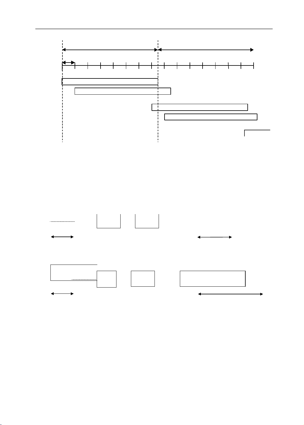
The PRACH is used to carry the RACH. The random-access transmission is
based on a slotted ALOHA approach with fast acquisition indication. The mobile station
can start the transmission at a number of well-defined time-offsets, denoted access slots.
There are 15 access slots per two frames and they are spaced 5120 chips apart. Figure
6.6 shows the access slot numbers and their spacing to each other. Information on what
access slots are available in the current cell is given by higher layers. The structure of
the random-access transmission is shown in Figure 6.7. The random-access
transmission consists of one or several preambles of length 4096 chips and a message
of length 10 or 20 ms. The mobile station indicates the length of the message part to the
network by using specific signatures.
The preamble part of the random-access burst consists of 256 repetitions of a
signature. There are a total of 16 different signatures, based on the Hadamard code set of length 16.
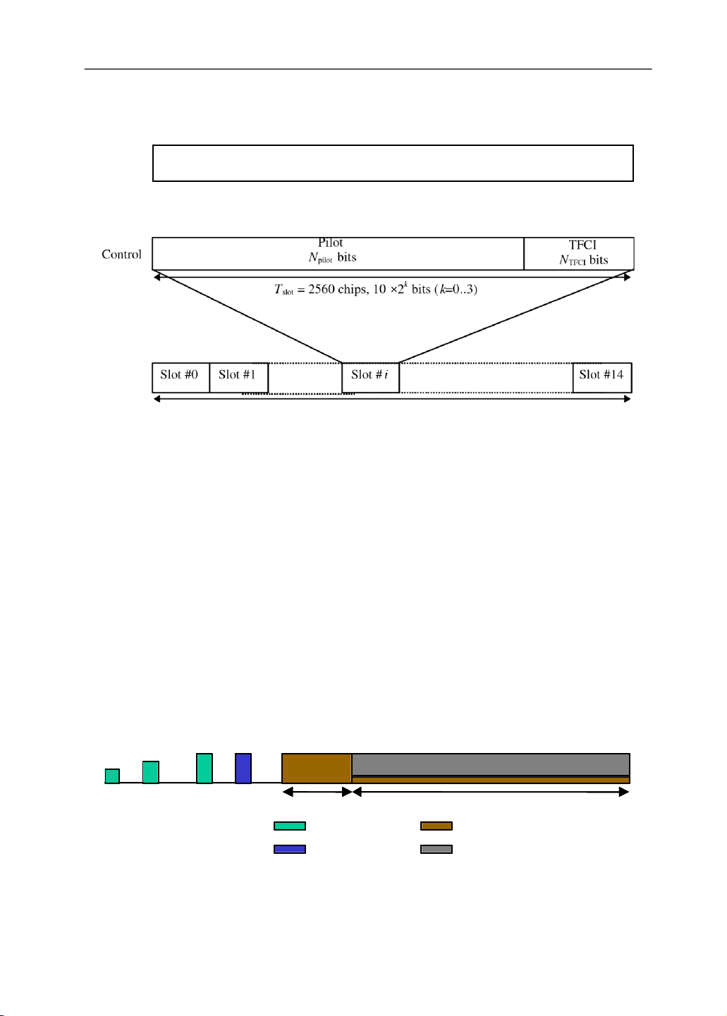
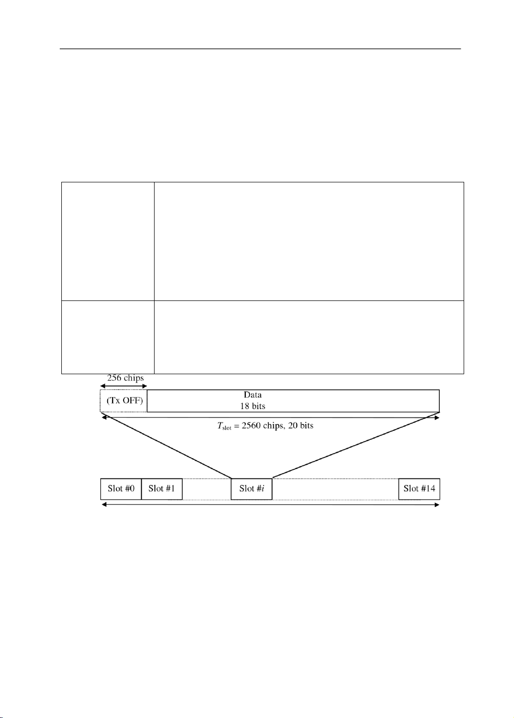
Figure 6.8 shows the structure of the random-access message part radio frame.
The 10 ms message part radio frame is split into 15 slots, each of length Tslot = 2560
chips. Each slot consists of two parts, a data part that carries layer 2 information and a
control part that carries layer 1 control information. The data and control parts are
transmitted in parallel. A 20-ms-long message part consists of two consecutive message part radio frames. lOMoAR cPSD| 58977565 WCDMA 181 radioframe:10ms radioframe:10ms 5120 chips #0 #1 #2 #3 #4 #5 #6 #7 #8 #9 #10 #11 #12 #13 #14 ccessslot#0 Random-access transmission ccessslot#1 Random-access transmission ccessslot#7 Random-access transmission ccessslot#8 Random-access transmission ccessslot#14
Figure 6.6 RACH access slot numbers and their spacing. (Source: [3], reproduced with permission from ETSI.) Preamble Message Preamble Preamble part 4096 chips 10 ms (one radio frame) Preamble Pream Preamble Message part ble 4096 chips 20 ms (two radio frames)
Figure 6.7 Structure of the random-access transmission. (Source: [3], reproduced with permission from ETSI.)
The data part consists of 10x2k bits, where k= 0, 1, 2, 3. This corresponds to a
spreading factor of 256, 128, 64, and 32, respectively, for the message data part. lOMoAR cPSD| 58977565 WCDMA 182
The control part consists of eight known pilot bits to support channel estimation
for coherent detection and two TFCI bits. This corresponds to a spreading factor of 256 for the Data message Ndata bits control part. Data
Message part radio frameTRACH = 10 ms
Figure 6.8 Structure of the random-access message part radio frame. (Source: [3], reproduced with permission from ETSI.)
The PCPCH is used to carry the CPCH transport channel. The CPCH
transmission is based on DSMA-CD approach with fast acquisition indication. The
mobile station can start transmission at a number of well-defined time-offsets, relative
to the frame boundary of the received BCH of the current cell. The structure of the
CPCH random access transmission is shown in Figure 6.9. The CPCH random-access
transmission consists of one or several access preambles of length 4096 chips, one
collision detection preamble (CD-P) of length 4096 chips, a DPCCH power control
preamble (PC-P) (which is either 0 slots or 8 slots in length), and a message of variable length Nx10 ms. Pj Pj P1 Messagepart P 0 4096 chips 0 or8slots Nx10msec DPCCH Accesspreamble DPDCH Collisionresolution preamble lOMoAR cPSD| 58977565 WCDMA 183
Figure 6.9 Structure of the CPCH random-access transmission. (Source: [3], reproduced with permission from ETSI.) 6.4.2
Downlink Physical Channels
There is one downlink dedicated physical channel, one shared and five common control channels:
• Downlink dedicated physical channel (DPCH);
• Physical downlink shared channel (DSCH);
• Primary and secondary common pilot channels (CPICH);
• Primary and secondary common control physical channels (CCPCH);
• Synchronization channel (SCH).
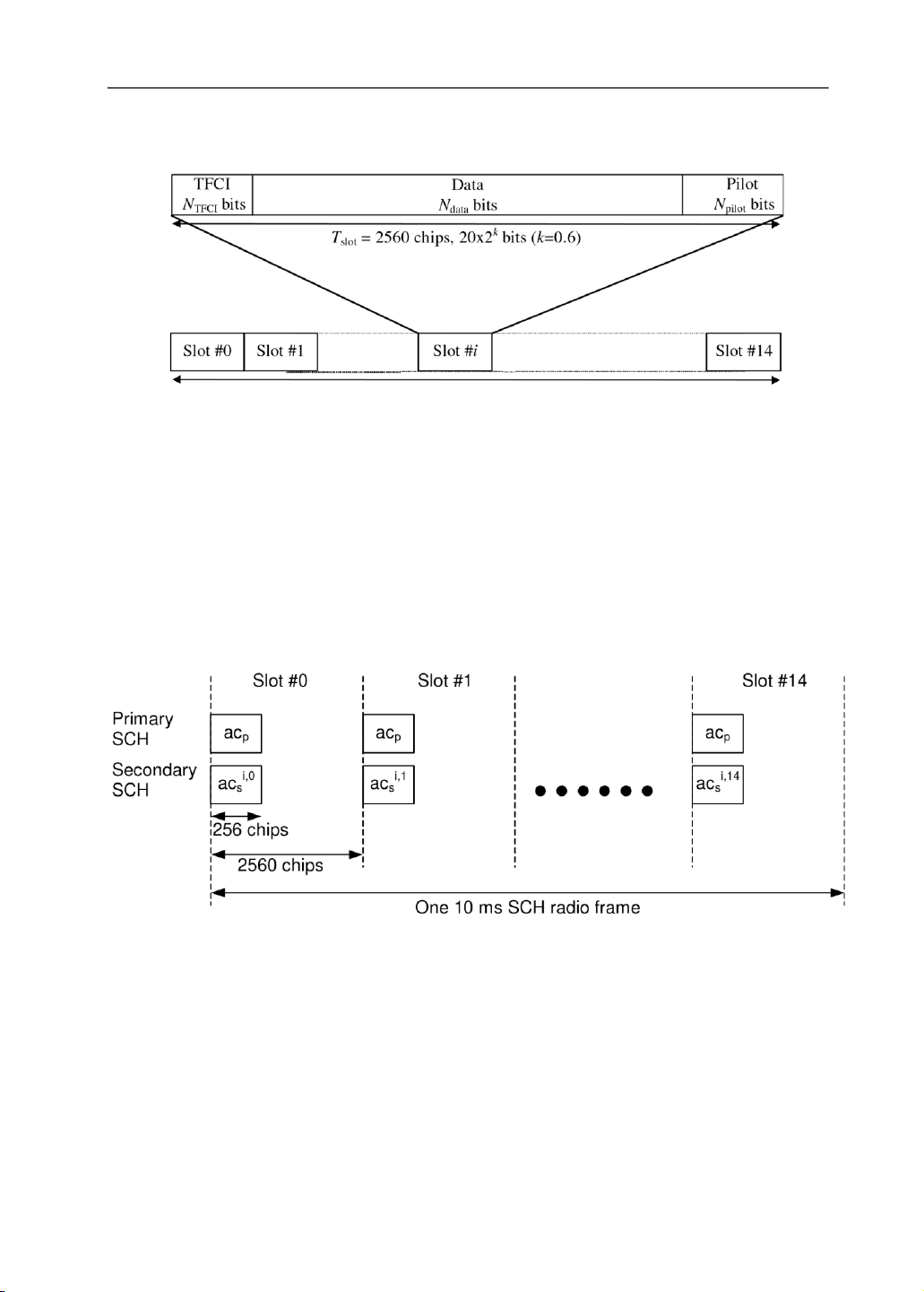
Figure 6.10 shows the frame structure of the DPCH. On the DPCH, the dedicated
transport channel is transmitted time multiplexed with control information generated at
layer 1 (known pilot bits, power-control commands, and an optional transport-format
combination indicator). DPCH can contain several simultaneous services when TFCI is
transmitted or a fixed rate service when TFCI is not transmitted. The network
determines if a TFCI should be transmitted.
When the total bit rate to be transmitted exceeds the maximum bit rate for a
downlink physical channel, multicode transmission is employed (i.e., several parallel
downlink DPCHs are transmitted using the same spreading factor). In this case, the layer
1 control information is put on only the first downlink DPCH.
One radio frame, Tf = 10 ms
Figure 6.10 Frame structure for downlink DPCH. (Source: [3], reproduced with permission from ETSI.)
Common pilot channel (CPICH) is a fixed-rate (30 Kbps, SF=256) downlink
physical channel that carries a predefined bit/symbol sequence. There are two types of
common pilot channels, the primary and secondary CPICH, as shown in Table 6.6. lOMoAR cPSD| 58977565 WCDMA 184
The primary CCPCH is a fixed-rate (30 Kbps, SF=256) downlink physical
channels used to carry the BCH. Common control physical channels are not inner-loop
power controlled. Figure 6.11 shows the frame structure of the primary CCPCH. The
primary CCPCH is not transmitted during the first 256 chips of each slot. Instead,
primary and secondary SCHs are transmitted during this period. Table 6.6 Primary and Secondary CPICH Primary CPICH
• Uses the same channelization code always;
• Scrambled by the primary scrambling code; • One per cell;
• Broadcast over the entire cell;
• The primary CPICH is the phase reference for the SCH, primary CCPCH,
AICH, PICH. It is also the default phase reference for all other downlink physical channels. Secondary CPICH
• Zero, one, or several per cell;
• May be transmitted over only a part of the cell;
• A secondary CPICH may be the reference for the secondary CCPCH and
the downlink DPCH. If this is the case, the mobile station is informed about
this by higher-layer signaling.
1 radio frame: Tf = 10 ms
Figure 6.11 Frame structure for primary CCPCH. (Source: [3], reproduced with permission from ETSI.)
The frame structure of the secondary CCPCH is shown in Figure 6.12. The
secondary CCPCH is used to carry the FACH and PCH. The main difference between
the primary and secondary CCPCH is that the primary CCPCH has a fixed predefined
rate while the secondary CCPCH can support variable rate. Furthermore, a primary
CCPCH is continuously transmitted over the entire cell while a secondary CCPCH is
only transmitted when there is data available and may be transmitted in a narrow lobe lOMoAR cPSD| 58977565 WCDMA 185
in the same way as a dedicated physical channel (only valid for a secondary CCPCH carrying the FACH).
1 radio frame: Tf = 10 ms
Figure 6.12 Frame structure for secondary CCPCH. (Source: [3], reproduced with permission from ETSI.)
Figure 6.13 depicts the structure of the synchronization channel (SCH) used for
cell search. The SCH consists of two subchannels, the primary and secondary SCH.
The primary SCH consists of a modulated code of length 256 chips, the primary
synchronization code (PSC) denoted cp in Figure 6.13, transmitted once every slot. The
PSC is the same for every cell in the system.
Figure 6.13 Structure of synchronization channel. (Source: [3], reproduced with permission from ETSI.)
The secondary SCH consists of repeatedly transmitting a length 15 sequence of
modulated codes of length 256 chips, the secondary synchronization codes (SSC),
transmitted in parallel with the primary SCH. The SSC is denoted c i,k
s , where i = 1, 2,
…, 64 is the number of the scrambling code group, and k = 0, 1, …, 14 is the slot number.
Each SSC is chosen from a set of 16 different codes of length 256. This sequence on the lOMoAR cPSD| 58977565 WCDMA 186
secondary SCH indicates to which of the code groups the cell’s downlink scrambling code belongs.
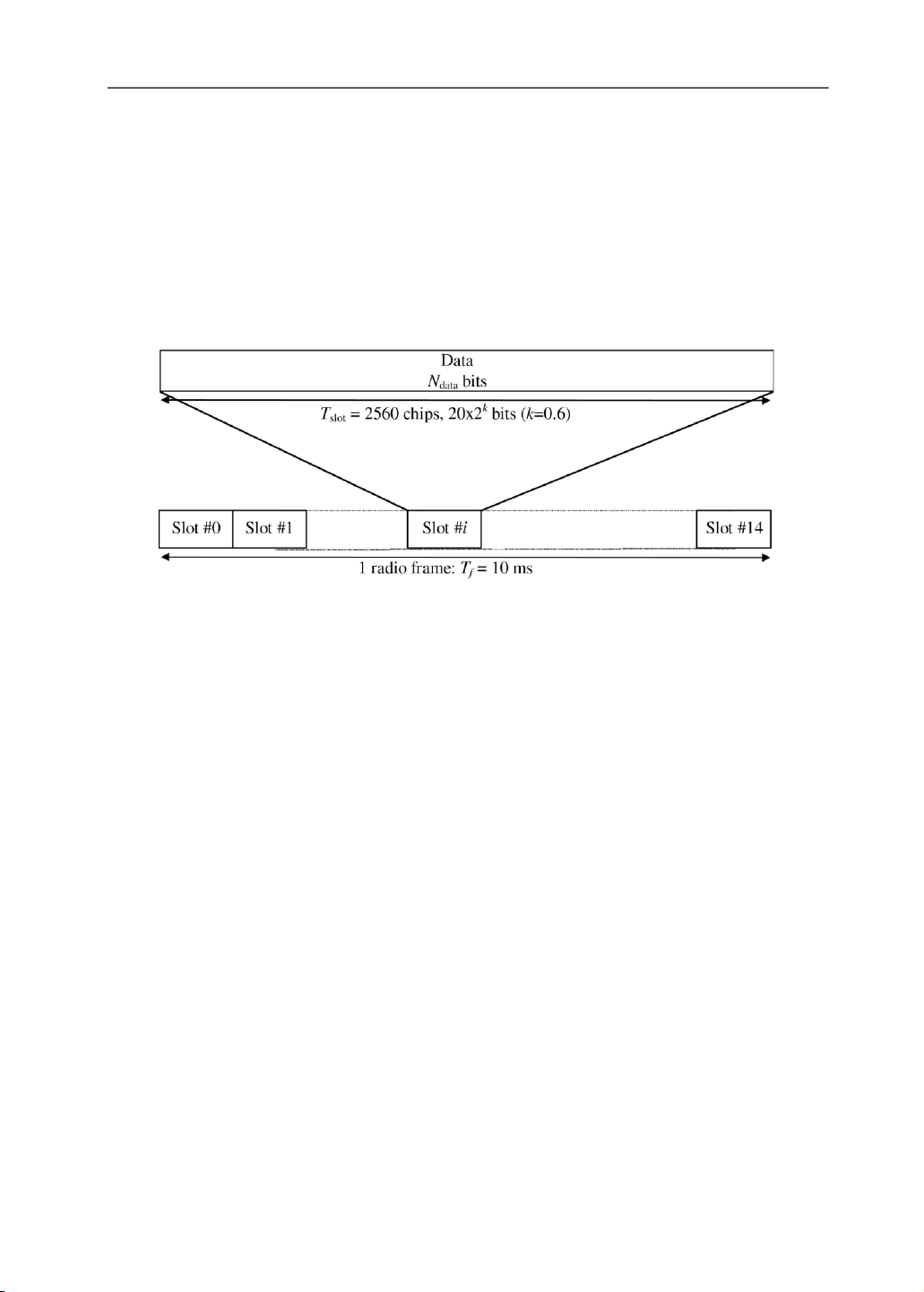
The physical downlink shared channel is used to carry the downlink shared
channel. It is shared by users based on code multiplexing. The structure of the PDSCH
is shown in Figure 6.14. As the DSCH is always associated with a DCH, the PDSCH is
always associated with a downlink DPCH. For PDSCH the spreading factors may vary
from 256 to 4. If the spreading factor and other physical layer parameters can vary on a
frame-by-frame basis, the TFCI shall be used to inform the mobile stations of the
instantaneous parameters of PDSCH.
Figure 6.14 Frame structure for the PDSCH. (Source: [3], reproduced with permission from ETSI.)
The acquisition indicator channel (AICH) is a physical channel used to carry
acquisition indicators, which correspond to signature s on the PRACH or PCPCH.
The page indicator channel (PICH) is a fixed-rate (SF=256) physical channel
used to carry the page indicators. The PICH is always associated with a secondary
CCPCH to which a PCH transport channel is mapped. 6.5
MULTIRATE USER DATA TRANSMISSION
WCDMA has a flexible multirate transmission scheme that enables transmission of
different types of services using different data rates and quality of service parameters.
For example, channel coding type, interleaving depth, and data rate can be varied to
achieve the desired quality of service.
Figure 6.15 and Figure 6.16 show the multirate transmission and multiplexing
schemes for the uplink and downlink, respectively. Data from transport channels is
encoded and thereafter mapped to the physical channels and transmitted over the radio
transmission link. The channel coding scheme is a combination of error detection, error
correcting, rate matching, interleaving, and transport channels mapping onto physical channels.
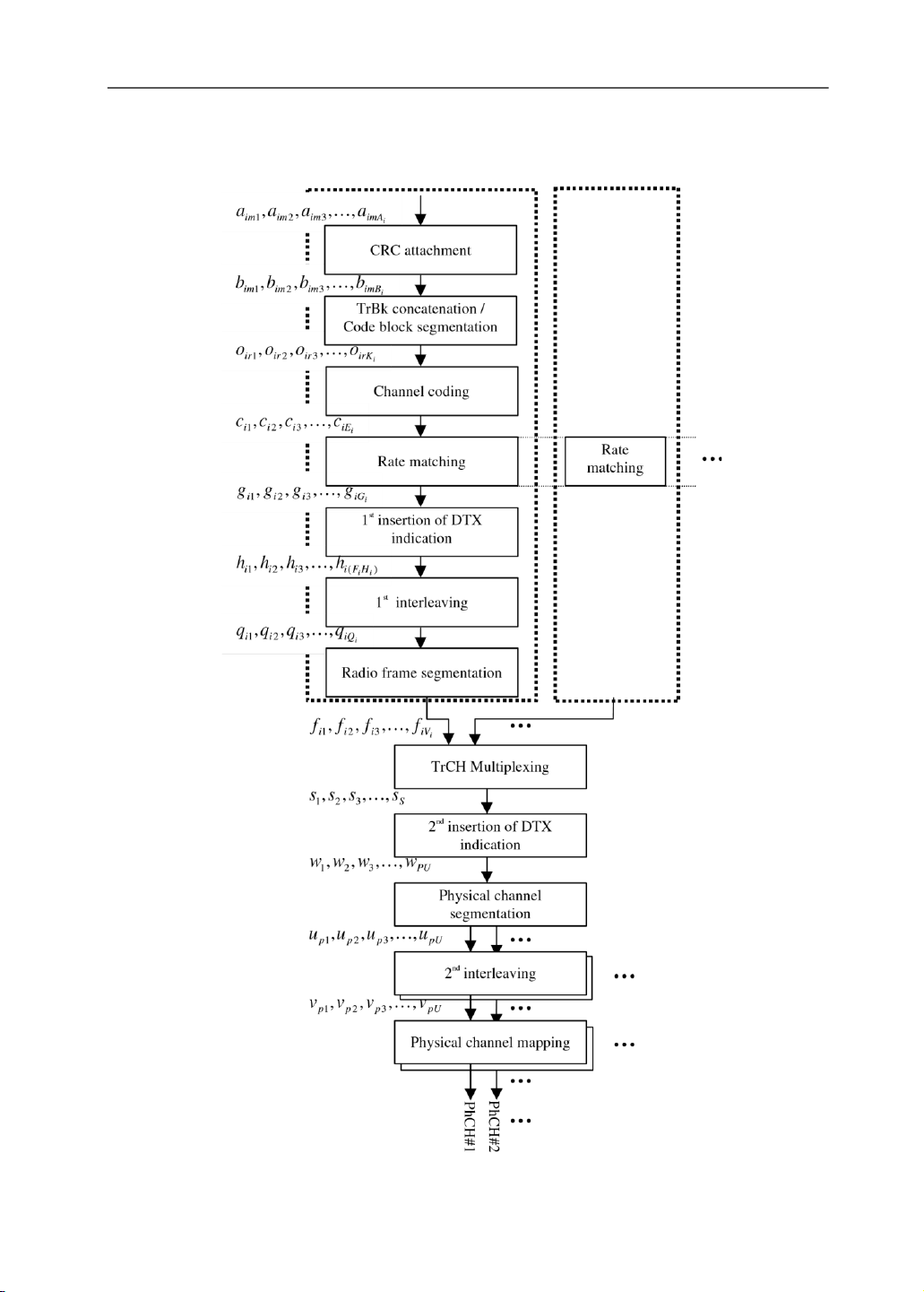
Data arrives to the coding/multiplexing unit in the form of transport block sets
once every transmission time interval, which is transport-channel specific and can be
10, 20, 40, or 80 ms. Multirate transmission consists of following steps: lOMoAR cPSD| 58977565 WCDMA 187
• Addition of cyclic redudancy check (CRC) to each transport block;
• Concatenation of transport block and segmentation of code block; • Channel coding; • Rate matching;
• Insertion of discontinuous transmission (DTX) indication bits; • Interleaving;
• Segmentation of radio frames;
• Multiplexing of transport channels; • Segmentation of physical channel;
• Mapping to physical channels.
Error detection is provided on transport blocks through CRC. The CRC is 24,
16, 12, 8, or 0 bits, and higher layers signal what CRC length should be used for each transport channel.
After CRC addition, transport block concatenation and code block segmentation
are performed. All transport blocks in are serially concatenated. If the number of bits in
the transmission time interval is larger the maximum size of the used code block, then
code block segmentation is performed after the concatenation of the transport blocks.
The maximum size of the code blocks depends on whether convolutional coding, turbo
coding, or no coding is used. The maximum code block sizes are:
• Convolutional coding: 504; • Turbo coding: 5114;
• No channel coding: unlimited.
Radio frame size equalization is padding the input bit sequence in order to ensure
that the output can be segmented in consecutive radio frames of the same size. Radio
frame size equalization is only performed in the uplink. In the downlink, rate matching
output block length is already suitable for radio frame segmentation.
When the transmission time interval is longer than 10 ms, the input bit sequence
is segmented and mapped onto consecutive radio frames. This enables interleaving over
several radio frames improving spectrum efficiency.
Because WCDMA provides flexible data rates, the number of bits on a transport
channel can vary between different transmission time intervals. The rate matching
adapts this resulting symbol rate to the limited set of possible symbol rates of a physical
channel. Rate matching means that bits on a transport channel are repeated or punctured
according to the defined rate matching attribute, which is semistatic and can only be
changed through higher layer signaling.
In the downlink the transmission is interrupted if the number of bits is lower than
maximum (i.e., DTX is used to fill up the radio frame with bits). The insertion point of
DTX indication bits depends on whether fixed or flexible positions of the transport
channels in the radio frame are used. It is up to the network to decide for each transport
channel whether fixed or flexible positions are used during the connection. DTX lOMoAR cPSD| 58977565 WCDMA 188
indication bits only indicate when the transmission should be turned off, they are not transmitted.
One or more physical channels can be used to transmit the result. When more
than one physical channel is used, physical channel segmentation divides the bits among
the different channels. After the second interleaving, physical channel mapping is performed. lOMoAR cPSD| 58977565 WCDMA 189 Figure 6.15
Multirate scheme for uplink. (Source: [4], reproduced with permission from ETSI.) lOMoAR cPSD| 58977565 WCDMA 190 Figure 6.16
Multirate scheme for downlink. (Source: [4], reproduced with permission from ETSI.) 6.5.1
Transport Format Detection
Transport format detection can be performed both with and without transport format
combination indicator (TFCI). If a TFCI is transmitted, the receiver detects the transport
format combination from the TFCI. When no TFCI is transmitted, so-called blind
transport format detection may be used (i.e., the receiver side detects the transport
format combination using some information, for example, received power ratio of
DPDCH to DPCCH or CRC check results). 6.5.2 Channel Coding
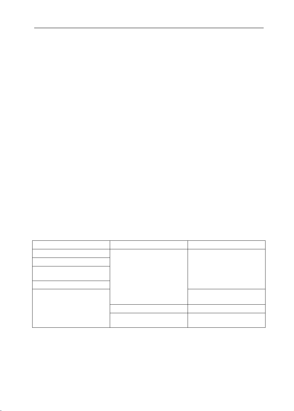
Table 6.7 lists the channel coding parameters for different transport channel types. The
following channel coding schemes can be applied:
• Convolutional coding with constraints length 9 and coding rate 1/3 or 1/2; • Turbo coding; • No channel coding.
The first and second interleaving are both block interleavers with intercolumn permutations. Table 6.7
Error Correction Coding Parameters Transport channel type Coding scheme Coding rate BCH Convolutional code 1/2 PCH RACH CPCH, DCH, DSCH, FACH 1/3, 1/2 Turbo code 1/3 No coding
The turbo coding scheme is a parallel concatenated convolutional code (PCCC)
with eight-state constituent encoders.
The initial value of the shift registers of the PCCC encoder shall be all zeros (see
Figure 6.17). The output of the PCCC encoder is punctured to produce coded bits
corresponding to the desired code rate. For rate 1/3, none of the systematic or parity bits are punctured.
Tài liệu liên quan:
-
Bài tập quy hoạch mạng hệ thống thu phát vô tuyến môn Thu phát vô tuyến | Học viện Công Nghệ Bưu Chính Viễn Thông
121 61 -
Tài liệu về RF transceiver architectures for W-CDMA systems like UMTS môn Thu phát vô tuyến | Học viện Công Nghệ Bưu Chính Viễn Thông
118 59 -
Tài liệu về Transmit diversity in 3G CDMA systems môn Thu phát vô tuyến | Học viện Công Nghệ Bưu Chính Viễn Thông
119 60 -
Tài liệu về Introduction to UMTS device testing môn Thu phát vô tuyến | Học viện Công Nghệ Bưu Chính Viễn Thông
120 60