Tài liệu về Transmit diversity in 3G CDMA systems môn Thu phát vô tuyến | Học viện Công Nghệ Bưu Chính Viễn Thông
The World Wide Web and increasing demand for wireless services (e.g., voice and data) are driving the demand for increased system capacity, data rates, and multimedia services. Tài liệu được sưu tầm gồm 9 trang, giúp các bạn nắm vững kiến thức, rèn luyện kỹ năng và đạt được kết quả tốt trong học tập. Mời các bạn đón xem!
Môn: Thu phát vô tuyến (TEL1416) 10 tài liệu
Trường: Học viện Công Nghệ Bưu Chính Viễn Thông 1.8 K tài liệu
Tác giả:


Preview text:
lOMoAR cPSD| 58977565
Transmit Diversity in 3G CDMA Systems
R. Thomas Derryberry, Steven D. Gray, D. Mihai Ionescu, Giridhar Mandyam, and Balaji Raghothaman,
Nokia Research Center contributing technologies to addressing this problem in these proposed 3G CDMA systems. 0163- ABSTRACT 6804/02/$17.00 © 2002 IEEE
Transmit diversity (TD) is one of the key
Multiple antennas can improve the performance
contributing technologies to defining the ITU
of a wireless communication system in a fading
endorsed 3G systems W-CDMA and cdma2000.
environment [1]. Although multiple antennas may be
Spatial diversity is introduced into the signal by
employed at either the base station, mobile station,
transmitting through multiple antennas. The
or both, it is most cost effective and practical to
antennas are spaced far enough apart that the
employ multiple antennas at the base station. Hence,
signals emanating from them can be assumed to
the topic matter of this article is restricted to the case
undergo independent fading. In addition to diversity
of employing multiple antennas at the base station.
gain, antenna gain can also be incorporated through
The spacing of the antennas also affects the
channel state feedback. This leads to the
degree of correlation between the channels from
categorization of TD methods into open loop and
the antennas to the mobile. Large antenna spacing,
closed loop methods. Several methods of transmit
on the order of several carrier wavelengths, leads to
diversity in the forward link have been either under
uncorrelated fading, which leads to maximum
consideration or adopted for the various 3G
performance gain due to spatial diversity.
standards. This article describes the concept of
Beamforming methods, on the other hand, utilize
transmit diversity and explains the features of
antenna spacing less than the carrier wavelength, selected TD techniques.
typically half the wavelength.
The rest of this article is organized as follows. We
provide the reader with an introductory overview of INTRODUCTION
diversity in general. We describe the different classes
The World Wide Web and increasing demand for
of TD and make summary remarks.
wireless services (e.g., voice and data) are driving
the demand for increased system capacity, data
TRANSMIT DIVERSITY BASICS
rates, and multimedia services. The International
Mobile Telecommunications in 2000 (IMT-2000) THE CHANNEL
standards development process, within the
Most mobile communication channels must combat
International Telecommunication Union (ITU), is
the effects of fading caused by multipath
driving the development of enhanced third-
propagation. An important way of quantifying
generation (3G) standards in order to address
fading is in terms of a measure called the coherence
current and future wireless service needs.
bandwidth which indicates the amount of
Particularly the Third Generation Partnership
bandwidth that will fade in a correlated fashion at
Project (3GPP) and Third Generation Partnership
any instant in time. To define this correlation,
Project Two (3GPP2) are developing the wideband
consider a linear model of a communication
code-division multiple access (WCDMA)
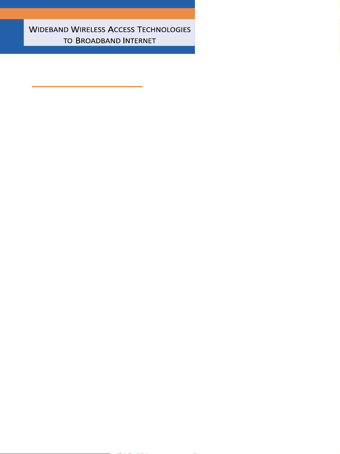
channel; Fig. 1a illustrates what is termed the delay
technologies and CDMA2000, respectively.
spread of the channel. Figure 1 offers a model
Improvement of downlink capacity is one of the
where the multipath arrivals decrease in power as a
main challenges facing the effort toward 3G
function of a discrete time index and Td is the
evolution. Many of the proposed services are
maximum duration of the mobile communication
expected to be downlink-intensive, and moreover
channel. The time index is a measure of the time of
likely to be used in low-mobility environments
arrival relative to the first multipath component at
under single-path conditions. Poor performance
time 0. Often, the “direct path” arrives first, and
due to prolonged deep fading of the channel is one
subsequent paths represent paths reflected at
of the problems associated with this model.
increasing distances from the receiver. Given Fig. 1,
Transmit diversity (TD) is one of the key
the coherence bandwidth is approximated by lOMoAR cPSD| 58977565
(typically path powers less than 5–10 percent of the total power are ignored)
antenna transmits without delay and the second
■ Figure 1. a) Delay profile; b) single-path envelope; c) two-path envelope. B ª
sends b[n] after a delay of one or more sample c 1 .
instants. The resulting waveform at the input to the 2 π pf c2 t 2 π pf c1 t
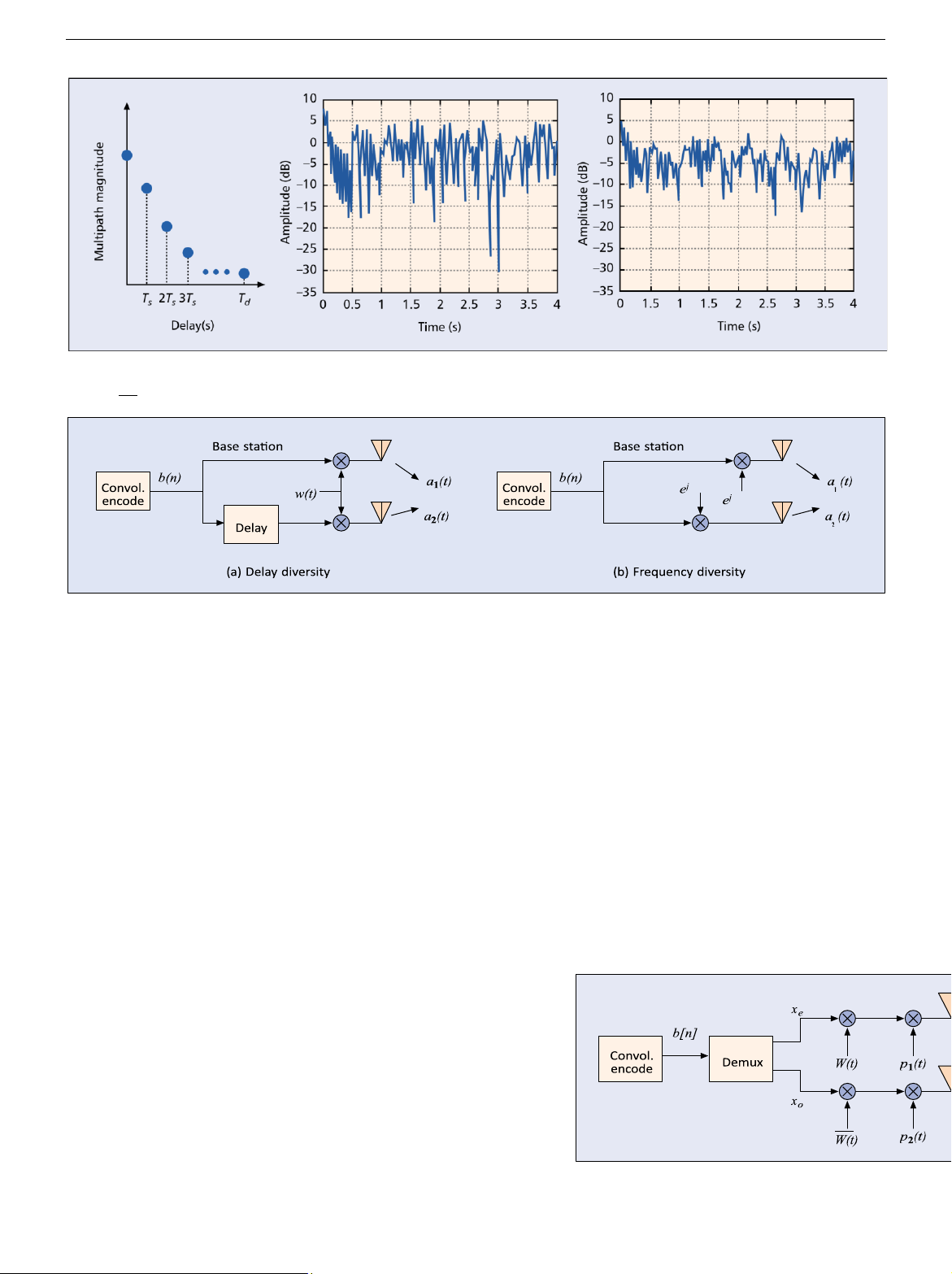
■ Figure 2. Delay diversity and frequency diversity. Td receiver is
Considering a communication system with bandwidth Bw, if Bc > Bw, the Xd( )t
channel between the transmitter and receiver is called a flat fading channel and
if Bc < Bw the channel is called a frequency selective channel.
= a t1( )Âb n w t[ ] ( -nT)+ a2( )t Âb n[ -1] (w t -nT)+g(
Flat fading channels are problematic for systems without TD, because a deep )t
fade can result in a received signal that is below the background noise level, n n
making communication unreliable. The worst type of channel conditions for many
communication systems are slowly changing flat fading channels; this is due to the
= Âb n a t w t[ ]{ 1( ) ( -nT)+ a2( ) (t w t - +(n1) )}T +g( )t
length of time the receiver cannot reliably demodulate the bits sent by the ,
transmitter. Using a simple model of the complex baseband communication signal n
S(t), the signal at a receiver from a flat fading channel is given by
where ak is the fading coefficient for an independent
X(t) = a(t) S(t) + g(t), where a(t) represents the channel coefficient subject to
flat fading channels, w(t) is the modulating
fading, and g(t) is an additive noise process. Figure 1b offers an example of a flat
waveform for each bit, and T is the amount of time
Rayleigh fading channel where a(t) is a complex Gaussian random process and
each bit is transmitted before moving to the next bit.
Ía(t)Í is Rayleigh distributed. When ÚÍa(t)Í2 dt < ÚÍg(t)Í2 dt, the strength of the
The effect of delay diversity on a slowly fading
communication signal is less than the background noise, making it difficult, in
channel is to allow the receiver to coherently add the
many cases, to recover S(t).
two independent fading channels together to aid in
Transmit diversity can improve the receiver performance in the presence of
demodulation. Typically, unique pilot symbols are
flat fading. It reduces the impact of fading by offering multiple independent sent on each antenna,
copies of the digitally modulated waveform at the receiver, where the chance
that all copies are simultaneously in a fade is very small. Common methods of TD
employing spatially separated antennas utilize either temporal or frequency
techniques, or combinations of these techniques.
TEMPORAL (DELAY) DIVERSITY
Delay diversity for two antennas, shown in Fig. 2, is a simple TD scheme that helps
combat flat fading. Bits in Fig. 2 are generated by a source consisting of
information from a computer, a digitized speech signal, or after being encoded by
a channel encoder. The bits are numbered such that a bit at time instant n is
denoted b[n]. The original bits are transmitted using two antennas, where the first
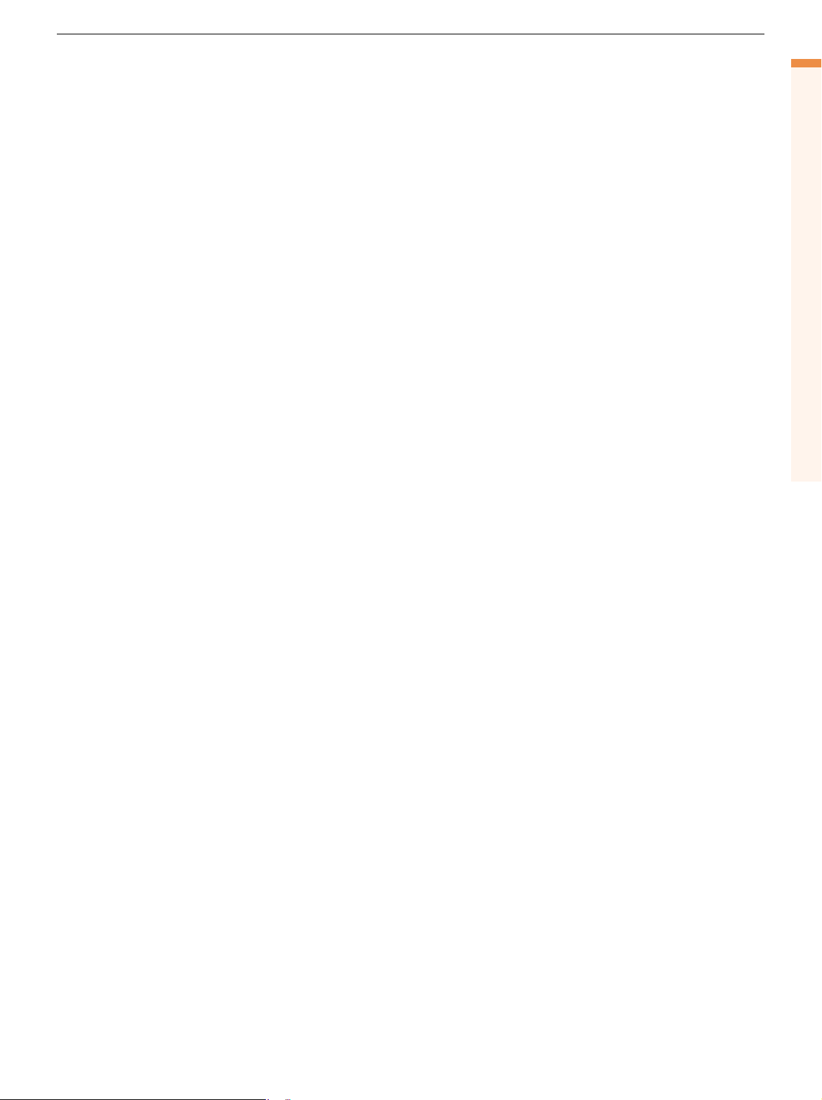
■ Figure 3. OTD transmitter. lOMoAR cPSD| 58977565
allowing the receiver to characterize the two
The most obvious disadvantage is that the channel
channels formed between each antenna and the
environment information is not utilized; that is, open
mobile. Considering a case where a1(t) and a2(t) are
loop techniques are a one-size fits all approach to
identically distributed complex Gaussian random
achieving TD for all mobile users.
processes, Fig. 1c shows the response of a(t)
The earliest open loop diversity techniques were =(Ía
simple in their configuration, for example, phase-
1(t)Í2 + Ía2(t)Í2)1/2. The fade depth, difference
between the peaks and valleys, is less in Fig. 1c than
switched TD (PSTD) and time-switched TD (TSTD).
that experienced in Fig. 1b. Thus, the resultant
PSTD introduces a known periodically varying phase
channel is more reliable from a communication
difference between the symbols transmitted through perspective.
different antennas to simulate fast fading. In TSTD
This approach suffers from reduced throughput
the transmission is switched among the different
due to multiple transmissions of the same symbol
antennas with a known periodicity. All antennas
over time. Another instance of temporal diversity
transmit the same symbol simultaneously at reduced
may be achieved in multipath channels where the
power, so the total power remains unchanged. Each
signal bandwidth is larger than the coherence
of these methods has been proposed at one time or
bandwidth of the channel; in this case the multipaths
another in the 3G CDMA standards bodies. TSTD was
are resolvable and may be recovered by a rake
adopted for use on the synchronization channel in
receiver. Frequency diversity methods similarly can
3GPP. However, PSTD was not adopted in favor of
improve the receiver performance in the presence of
other techniques such as orthogonal TD (OTD) [2], flat fading.
space-time TD (STTD) [3], and space-time spreading (STS) [2]. FREQUENCY DIVERSITY
Frequency diversity methods (Fig. 2b) employ
ORTHOGONAL TRANSMIT DIVERSITY
transmission of multiple symbol replicas over
Orthogonal TD [2] is an open loop method in which
multiple carriers, each separated in frequency by a
coded interleaved symbols are split into even and
sufficiently large amount to ensure independent
odd symbol streams and transmitted using two
fading. To ensure independent fading employing this
different Walsh codes. The length of the Walsh code
technique, the difference between the two carriers,
is doubled so that the total number of Walsh codes f
available is not reduced as a result of splitting the
c1 and fc2, must be greater than the coherence bandwidth (i.e., Íf Í ≥
data, and the data rate will remain more constant c1 – fc2 Bc).
Using notation as described in the previous
than is the case with no data splitting. Consider the
section, the resulting waveform at the input to the
two-antenna case. Let xo and xe be the odd and even receiver is
symbols, respectively. Then the symbols transmitted
over the two antennas, S1 and S2, are given by Xd ( )t S1 = xeW, = a t ( ) t  — 1
b n e[ ] j2pfc1(t-nT ) + a2( )
b n e[ ] j2pfc2(t-nT ) n n S2 = xoW, +g — ( )t
where W, W are complementary Walsh codes used {
(same chip rate, covering twice as many chips as in =Âb n a t e[ ]
1( ) j2pfc1(t-nT ) +a2( )t e j2pfc2(t-nT )¸˝˛+g( ).t n
the absence of OTD, but in the same number). The
signal received at the mobile receiver will be
r = h1s1 + h2s2 + g,
Similar to TD, the effect of frequency diversity for
where h1, h2 are the channels from the two antennas
a slowly fading channel is to allow the receiver to
to the MS, and p1(t) and p2(t) are the antenna-
coherently add the two independent fading channels
specific pilot signals, as shown in Fig. 3. The time
together to aid in demodulation. This approach is
subscripts have been left out for brevity. The
accompanied by the additional cost of increased
received signal from the two antennas is despread
complexity at both the transmitter and receiver,
using the same Walsh codes, and then combined to
along with the fact that it may be difficult to
recover the original symbol stream.
implement in bandwidth-limited systems. Given this
brief overview of TD basics, our attention focuses
TRANSMIT DIVERSITY VIA SPACE-TIME
more specifically on the issues of TD in the context of CODING 3G CDMA evolution.
Several methods of TD have been proposed for
Space-time coding is a means of enhancing the level
3G CDMA evolution. These can be broadly
of diversity presented to a receiver in a wireless link,
categorized into open loop and closed loop
via the addition of TD and in order to more efficiently techniques.
combat the signal fading inherent to wireless
OPEN LOOP TRANSMIT DIVERSITY IN 3G
communication channels. Motivated by the
information-theoretic results by Foschini and Gans
In open loop diversity methods, a predetermined form of diversity is introduced
[4] and Telatar [5], early ideas on TD schemes (e.g.,
using multiple antennas. Advantages of this class of methods include:
delay diversity, in which a second antenna transmits
• Signaling overhead is not required toachieve this form of diversity.
a delayed replica of another transmit antenna’s
• The mobile station (MS) receiver complexity is kept relatively low.
signal) have been refined by the work of Tarokh et al.
[6]. Since it is advantageous to separate the problem lOMoAR cPSD| 58977565
of combating fades from that of channel equalization, the criteria for designing
takes advantage of the uncorrelated fading across
spacetime codes are usually derived in the context of narrowband modulation and
the L transmit antennas without incurring any
frequency nonselective fading. The noteworthy fact about this approach is that it bandwidth expansion. STTD is an open-
isolates TD from those forms of diversity associated with the radio channel (e.g.,
In the case of full rate transmission, L = l. In this loop
due to multipath). Nevertheless, spread spectrum systems in frequency selective
situation, an orthogonality property for the square
channels can benefit equally from coding with space and time redundancy, as
space-time block code matrices [6], allows easy technique in which outlined below.
recovery of the symbols arriving from different the
In general, coding with space and time redundancy is accomplished by finding
transmit antennas despite their superposition (in
an efficient way to allocate different symbols to different antennas while adding,
time) at the receiver’s input. For complex modulator symbols are
jointly across antennas, some type of time redundancy for implementing forward
constellations the only known rate one constructions modulated using
error correction. For each of the symbol streams associated with different
are 2 ¥ 2 (i.e., for two transmit antennas). The
antennas, the system can then resort to other means to combat frequency
construction for two transmit antennas was first the technique
selective fading. For example, orthogonal frequency-division multiplexing (OFDM)
proposed by Alamouti in [3] and is defined by the
naturally lends itself to being used in conjunction with TD; likewise, when the described in. simple 2 ¥ 2 pattern,
excess delay is small, space-time block coding (see below) can easily be used in a This type of open-
maximal ratio combining receiver for frequency selective channels.
Space-time coding can be implemented in either block [3, 6], or trellis form [7]. È xo xe ˘ loop
Irrespective of form, transmission over L transmit antennas can be represented by transmit diversity a code matrix, ÍÍÎ- ˙˙ x* * ˚ e xo , has been adopted È c( )k1 c( )k2 where x by the 3GPP, due
o, xe are valid complex symbols from the Í
signal constellation (same on both antennas). ˘ to the fact that c ˙
( )k2+1 c( )kL
Matrices like this are unitary, cover two symbol c Í c( )k1+1
epochs, and allow easy recovery of xo, xe at the this type of D = Í Í
c( )kL+1 ˙˙,
receiver given the channel state [3, 6]. Alamouti’s
Î k+ -l 1 k+ -l 1 k+ -l 1 ˚ transformation
idea, based on the Hurwitz-Radon transform, was ( )2 ˙
further refined by Tarokh et al. [6]. maximizes
where the columns represent antennas Í ( )1 ( )L ˙ diversity gain. an
d the rows correspond to modulator
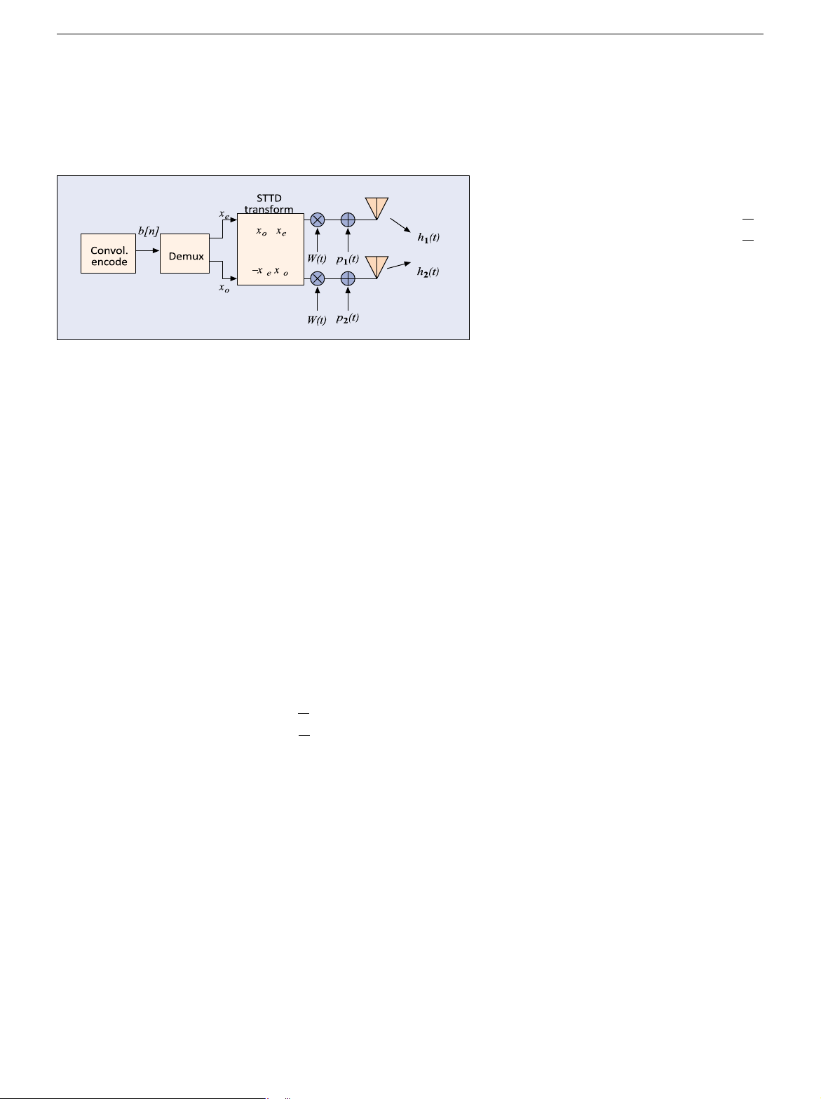
Space-Time Transmit Diversity — STTD is an open c c c
symbol epochs; here, c(1)n is the complex
loop technique in which the symbols are modulated
symbol, transmitted at symbol epoch n, from the modulator constellation used
using the technique described in [3]. This type of
on the ith transmit antenna, and c refers to the vector obtained by reading Dc
open loop TD has been adopted by the 3GPP because
row-wise. A code matrix covers l symbol epochs, starting with the kth symbol
this type of transformation maximizes diversity gain.
and ending with the one indexed by (k + l – 1); here, l is a meaningful number of
STTD is defined for two antennas. Assume once
epochs. For example, in a trellis-based implementation, l could cover a again that x
codeword or frame forced to start and end in the zeroth state; in a block space-
o and xe are the odd and even symbols,
respectively. Then the transmissions over the two
time code, l spans a block of symbols that are processed together during antennas, s detection [6]. 1 and s2 are given by
Space-time block codes of rate one are based on constructing code matrices
of size L ¥ L, such that each complex symbol (arising from a group of encoder
s1e = x Wo ,
output symbols after mapping to the relevant modulator constellation) is
s2e = x We ,
transmitted by any one antenna only once (possibly complex conjugated and/or scaled by ± —
1, ±j; here j denotes ÷–1). In effect, this implements a
s1o = - x W*e, modulator that
s2o = x W*o ,
where W is the orthogonal Walsh code used (Fig. 4).
The received symbol is decoded over two
consecutive time epochs. The received symbol may
be represented in vector form as Í
È re ˘˙ = ÈÍ h x W1 o*+-h x Wh x W22 e*o
˙˘˚˙ + ÍÍÎÈgg oe ˙˙˚˘.
ÎÍro ˚˙ ÍÎ-h x W1 e
Neglecting the Walsh codes, an estimate of the
transmitted symbols may be formed as
È ˆxe ˘˙ = ÈÍh2*re - h r1 o* ˘˙. Í lOMoAR cPSD| 58977565
ÍΈxo ˙˚ÍÎh1*re + h r2 o* ˙˚ channels, thereby experiencing diversity
The STTD scheme is particularly simple, in the sense that it implements due to lack of fading
Alamouti’s spacetime block code (2 ¥ 2 code matrices, see above) and follows it correlation across
by separate spreading and scrambling, as in the nondiversity mode. The transmit antennas and
orthogonality property of the code matrices allows the symbols from the two independent of
transmit antennas to be separated at the receiver front-end. There is no need for interleaving.
separate Walsh codes on the two trans- The recovery of the symbol stream is as shown below: ˆ x * * o = r
■ Figure 4. STTD transmitter. W
mit antennas for the traffic channel because the h
orthogonality between space-time code matrices is
realized in the time domain, just as in frequency 1
nonselective fading. However, separate Walsh codes *
are needed for the antenna pilot signals in order to distinguish the channels. +
Space-Time Spreading — STS [2] is another open- (
loop technique in which the symbols are spread
using multiple Walsh codes. It differs slightly from r
STTD, as explained below. Of course, apart from
Walsh spreading, the symbols are spread by a long W
spreading code, but this will be self-understood and h
omitted here for simplicity. The differences from
STTD arise in the need for STS to be compatible with 2
certain details of the IS-2000 specifications, in
particular OTD. This was not the case within the *
3GPP standard, which made the implementation of
STTD much more straightforward. *
Using similar notation as in an earlier section, the
symbols transmitted over the two antennas are ) , s = - 1 x Wo x W*e, ˆ s = + 2 x We x W*o , x
where (.)* stands for the conjugate operator. STS is e
another simple implementation of Alamouti’s
construction [3], based on the Hurwitz-Radon trans- =
— form [6]. If one views W, W as playing the roles of
the two transmit antennas, the Alamouti pattern in r
terms of xe, xo is easily recognizable; this is no sur-—
prise since W, W are, de facto, associated with the W
two antennas. The trick is that although the symbols
in the even and odd streams completely overlap in h
time (just as in OTD), they are distinguishable due to spreading by the orthogonal 2
— Walsh codes W, W. In
other words, we do not need two symbol epochs to *
implement the orthogonal space-time block pattern;
orthogonality of two disjoint time epochs has been -
replaced by orthogonality in the spreading code
domain. The result is that any symbol in both the (
even and odd streams is exposed to both fading lOMoAR cPSD| 58977565 rWh * * 1 ) .
from the two antennas are so closely spaced in time
of arrival at the MS that they are indistinguishable.
Now ^xe, ^xo are concatenated and input to the decoder for demodulation. We
Ignoring the time subscripts, the signal received at
stress that the advantage of STS over OTD is that all symbols are transmitted over the MS will be
all antennas; hence, it provides the addition of temporal diversity in the form of
repetition coding prior to the decoding process.
SCHEMES FOR MORE THAN TWO ANTENNAS
[ ]Èw1 ˘˙b + g y
Theoretically, the number of antenna elements through which independent
channels can be transmitted bound the achievable order of spatial diversity. A few = h Í 1 h2
open loop schemes have been proposed for four antennas: ÍÎw2 ˙˚
• A concatenation of the OTD scheme men-tioned earlier and the STS scheme
has been proposed as a diversity technique using four antennas [8]. = hwb + g ,
• An extension of the Alamouti scheme in anearlier section for three or four
antennas called ABBA has been proposed [9]. It has been proven that
where g refers to the additive noise. In order to
orthogonal designs do not exist for complex channels for four antennas.
maximize the received signal power, the optimal
Hence, this is a suboptimal construction, which involves some interference
transmit weights are given by w = hH/hhH.
cancellation along with space-time decoding.
The weights are normalized so that the total
transmitted power is not altered. In the case of
multipath channels emanating from each antenna (if C
h were a matrix instead of a vector), the optimal
LOSED LOOP TRANSMIT DIVERSITY IN 3G
weights will be given by the principal eigenvector of
Closed loop diversity techniques are adaptive in nature. The BS obtains knowledge
the channel correlation matrix hHh.
of the downlink channel from the MS via feedback signaling, and uses this
Thus, the MS calculates the weights at periodic
knowledge to its advantage. The use of feedback in transmit antenna arrays was
intervals from the information h obtained through
first proposed by Gerlach and Paulraj [10] as transmit beamforming. They
the two strong pilot signals P1 and P2. These weights
proposed that training signals be transmitted periodically on the downlink and the
are quantized and then fed back to the BS on the
responses of the various MSs fed back to the BS. This information is used to
reverse link control channel. It is also worth noting
calculate the optimal transmit weights for each mobile such that the received
that the STD method described previously is actually
power at the desired MS is maximized and interference to other MSs is minimized.
a subset of TXAA, with the weights being [0 1] or [1
These TD techniques can be described as customized to fit the channel conditions 0]. for each mobile user.
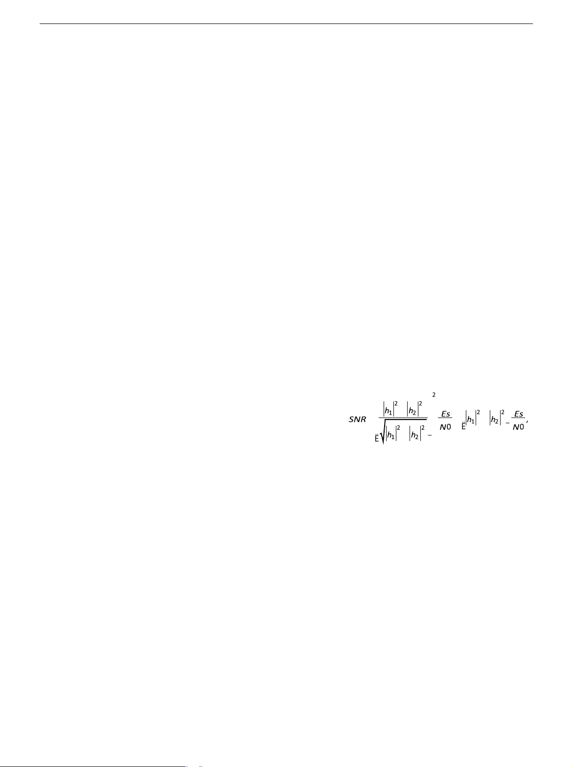
If one assumes that the feedback mechanism in
As explained at the beginning, the goal of inducing diversity runs somewhat
TXAA perfectly tracks the channel conditions of the
contrary to that of inducing directionality using beamforming in that the antennas
downlink, the signal-to-noise ratio (SNR) after
have to be spaced far apart. But the problem formulation for calculating the
demodulation and channel estimation is bounded as
antenna weights remains the same if one recognizes the fact that knowledge of Ê ˆ
the different channel coefficients is equivalent to knowledge of the directional Á + ˜
array manifold vector in the case of beamforming. In this sense, the closed loop Ê ˆ £ Á ˜ = Á + ˜
diversity techniques considered in the 3G standards are variants of the approach Á ˜ Ë ¯
in [10]. In fact, correlated fading models for multiple antennas and closed loop Á + Ë ˜ ¯
solutions for the same have been considered recently in these fora, arising when
operators are constrained by considerations of space from placing antennas close to each other at the BS.
SWITCHED TRANSMIT DIVERSITY
Switched TD (STD) is an extension of the open loop technique, TSTD. In this
scheme, the symbols are transmitted over one antenna at any given time. The MS
uses the average received power from the common pilots from each antenna, and
makes a decision as to from which antenna it would like the BS to transmit. This
decision is then conveyed to the BS through a feedback channel. This technique
has been proposed in the 3G CDMA standards bodies, but a more general and
aggressive form of STD was adopted by 3GPP: TXAA.
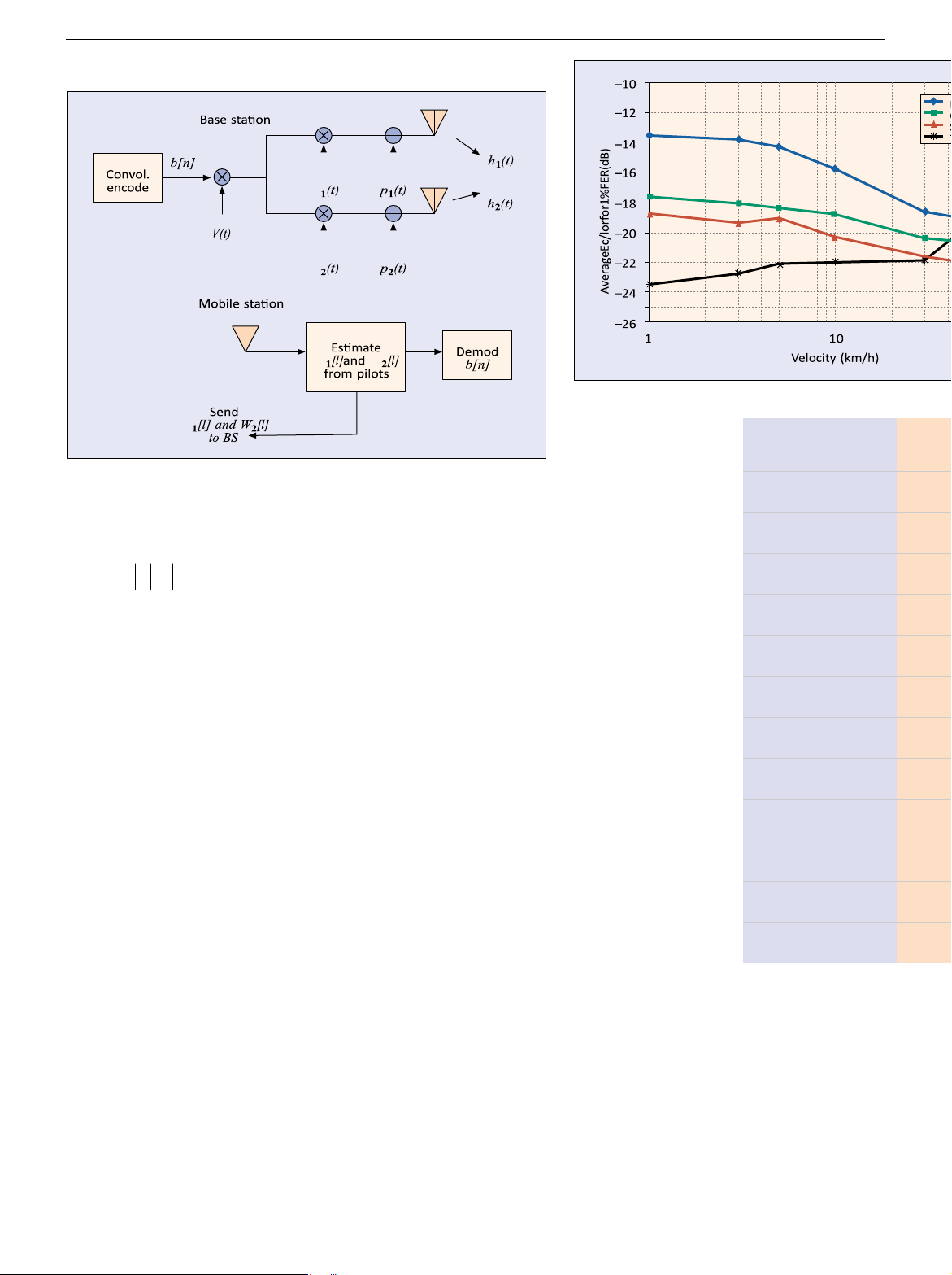
TRANSMIT ADAPTIVE ARRAY
Transmit adaptive array (TXAA) is a technique in which the MS periodically sends
quantized estimates of the optimal transmit weights to the BS via a feedback
channel The transmitter weights are optimized to deliver maximum power to the
MS. Figure 5 depicts the concept of TXAA.
Proceeding into more detail, consider a channel model with a single path
channel emanating from each of the two BS antennas denoted h1(t), h2(t) and
depicted in Fig. 5. The discussion can also easily be extended to the case of M
antennas (M > 2). Since artificially induced diversity is most advantageous in the
case of flat fading, we will consider the one path case here. Results can also be
demonstrated for multipath channels. Let the transmitter antenna weights for the
current instant be w1 [l], w2 [l]. Let b[n] be the data symbol at the current instant
and v(t) the user’s specific spreading sequence. The discrete time subscripts on w
and b are different since their periodicities are different. We assume that the paths lOMoAR cPSD| 58977565
where Es/N0 is the symbol SNR based solely on transmitted signal energy. In W W W W
■ Figure 6. Performance of TD methods. W Number of base statio n 2 antennas
comparison, from ■ Figure 5. Transmit adaptive array method. Carrier frequency 2 GHz
an earlier section it can be shown that the maximum achievable SNR of STTD after channel estimation is Bit bate 9600 b/s 2 2 Chip rate 1.2288 Mchip/s h1 + h2 Es SNR £. Walsh code length 128 chips 2 N0
Clearly, the maximum SNR of STTD cannot be greater than the maximum SNR Convolutional code Rate 1/4, K = 9
of TXAA. Details of TXAA may be found in [11] and its associated references. I Frame duration 20 ms. SSUES AND SOLUTIONS
Precision — Under the ideal conditions of infinite precision instantaneous
feedback, closed loop schemes with feedback offer a substantial performance Pilot Ec/Ior –7 dB
advantage over schemes without feedback under slow flat fading conditions.
However, several issues arise in the practical implementation of these schemes. Power control On
Limited availability of feedback capacity makes the precision of the feedback an
important factor. In fact, in WCDMA, a feedback capacity of 1500 b/s is assumed, Channel estimation
which amounts to 1 b/slot. Several methods have been used to convey channel Windowed (nonideal) information at this bit rate:
• Quantize the complex feedback coefficientto 1 bit of magnitude and 3 bits of Channel model Flat Rayleigh fading
phase and send them over successive slots [12].
• Feedback only the phase information forthe complex coefficients. Set Fading correlation 0
partitioning is done on the phase constellation, and the transmit weighting
is calculated by filtering over multiple feedback bits [12]. Feedback error rate 4%
Feedback Error — The feedback bits are not protected through FEC; hence, the
weights applied at the BS transmitter antennas might be different from the
■ Table 1. Simulation
weights the MS expects it to apply. This causes the composite channel estimate at parameters.
the MS receiver to be in error. In order to avoid this situation, verification of the
weights is necessary at the MS. Using the channel esti- mates from the common pilots as well as the dedicated pilot symbols embedded in the traffic channels, the applied weight may be estimated using hypothesis testing. lOMoAR cPSD| 58977565
Another solution proposed for the feedback error
beamforming with transmit diversity are some
problem was to use a decision-directed method
other technology areas that are promising for future
wherein, in case of a frame error, the erroneous evolution.
output bits are used to create a replica of the frame
and compared with the received frame in order to REFERENCES
determine the weights used in each slot in the frame
[1] W. C. Jakes, Microwave Mobile Communications, New York: [11]. IEEE Press, 1974.
[2] TIA/EIA IS-2000 Physical Layer Specification for CDMASpread
Feedback Delay — The MS using channel state
Spectrum Communications System, June 2000.
[3] S. M. Alamouti, “A Simple Transmit Diversity Techniquefor
information available to it at any given instant
Wireless Communications,” IEEE JSAC, vol. 16, Oct. 1998, pp.
estimates the required feedack. But there is a 1451–58.
definite delay involved in transmitting the
[4] G. J. Foschini, and M. J. Gans, “On Limits of
information back to the BS. In fast fading conditions,
WirelessCommunications in a Fading Environment When Using
Multiple Antennas,” Wireless Pers. Commun., Mar. 1998, pp.
this delay causes the transmit weights to be 311–35.
outdated by the time they are applied at the BS [13].
[5] E. I. Telatar, “Capacity of Multi-Antenna Gaussian Channels,”
One possible solution to this problem is to use the
AT&T Bell Labs. tech. rep., June 1995.
[6] V. Tarokh, H. Jafarkhani, and A. R. Calderbank, “SpaceTime
fact that the fading channel can be modeled as an
Block Codes from Orthogonal Designs,” IEEE Trans. Info.
auto-regressive (AR) process [14]. Linear prediction
Theory, vol. 45, July 1999, pp. 1456–67.
techniques can be used to estimate the AR
[7] S. Bäro, G. Bauch, and A. Hansmann, “Improved Codesfor
Space-time Trellis-coded Modulation,” IEEE Commun. Lett.,
coefficients and also to predict the future state of the
vol. 4, Jan. 2000, pp. 20–2.
channel. The mobile can calculate the feedback
[8] M. Harrison and K. Kuchi, “Open and Closed LoopTransmit
based on the predicted future channel state, thus
Diversity at High Data Rates on 2 and 4 Elements,” 3GPP2-C30-
reducing the effect of feedback delay.
19990817-017, Portland, OR, 1999.
[9] B. Raghothaman et al., “Performance of Simple Space Time
Block Codes for More than Two Antennas,” Proc. Allerton
SCHEMES FOR MORE THAN TWO ANTENNAS
Conf. Commun., Control and Comp., Oct. 2000.
The same principles discussed so far for two antenna elements can be used for
[10] D. Gerlach and A. Paulraj, “Adaptive TransmittingAntenna
Arrays with Feedback,” IEEE Sig. Proc. Lett., vol. 1, no. 10,
extensions of closed loop schemes to more than two transmit antennas. One Oct. 1994, pp. 150–52.
method being contemplated is the direct extension of the filtered phase
[11] B. Raghothaman, R. T. Derryberry, and G. Mandyam,“Transmit
feedback scheme in a previous section with a lower feedback rate per antenna.
Adaptive Array without User-Specific Pilot for 3G CDMA,” Proc.
ICASSP 2000, Istanbul, Turkey. [12] TS 25.214 3GPP TSG RAN
There is a question about the feasibility of placing many antennas spaced far
WG4, v. 3.2.0, Physical Layer Procedures (FDD), 2000-03.
enough to provide independent fading paths due to space constraints. Closer
[13] B. Raghothaman, G. Mandyam, and R.T. Derryberry,
spacing can induce partial correlation between diversity paths. A method called
“Performance of Closed Loop Transmit Diversity with Feedback
the eigen-beamformer has been proposed by Siemens to take advantage of the
Delay,” Proc. Asilomar Conf. Sig., Sys. Comp., 2000.
[14] T. Eyceoz, A. Duel-Hallen, and H. Hallen, “Deterministic
quasi-stationary property of this correlation. The eigenvectors of the correlation
Channel Modeling and Long Range Prediction of Fast Fading
matrix are fed back at a slow rate. The short-term feedback indicates to the BS
Mobile Radio Channels,” IEEE Commun. Lett., vol. 29, Sept.
some linear combination of the vectors to be used as the antenna weights. A 1998, pp. 254–56.
[15] “Enhancing the Beamforming Feature of the MultipleAntenna
similar concept involving multiple banks of beamforming antenna arrays has been
Tx Diversity,” TSGR1 #15(00)-1065, Fujitsu cont. to 3GPP.
proposed by Fujitsu. Details of the schemes briefly described in this subsection BIOGRAPHIES
may be found in [15] and its associated references.
R. THOMAS DERRYBERRY (tom.derryberry@nokia.com) earned his B.S. Polarization
(1985) and M.S. (1987) in electrical engineering from the University
of Arkansas and his Ph.D. (1995) in electrical engineering from diversity, space-
A COMPARISON OF TRANSMIT DIVERSITY
Southern Methodist University. From 1988 to 1998 he held positions
with Texas Instruments and Raytheon Systems. In 1998 he joined time trellis coding M
Nokia Research Center, Dallas, Texas, where he is currently an ETHODS
assistant research manager. He served as the chair of the Adaptive and modulation,
This section compares the performance of different OL and CL methods. The
Antennas Ad Hoc group within the 3GPP2, and remains active in
3GPP2. He is a member of Eta Kappa Nu.
results were generated in a symbol-level simulation environment for the and the
CDMA2000 standard. The simulation parameters are given in Table 1. Figure 6
STEVEN GRAY earned his B.S. with high honors (1985) and M.S. (1986) combination of
shows the average power per chip required to transmit at a given frame error
in electrical engineering from Texas A&M University, and his Ph.D.
(1995) in electrical engineering from Northeastern University. From
rate with power control. It can be seen that the open loop methods are robust at intelligent
1986 to 1996 he held positions with Sandia National Laboratories,
higher velocities, while TXAA provides the biggest benefit at the lower velocities.
E-Systems, and The MITRE Corporation. In 1996 he joined Nokia to beamforming with
To optimize the system performance the curves in Fig. 6 suggest that a mixture
develop CDMA and broadband wireless systems. Currently, he is
of open and closed loop diversity could be entertained to combat fast and slow
head of the Radio Communications Laboratory within Nokia transmit
Research Center. He is a member of Eta Kappa Nu and Tau Beta Pi.
fading, but this would require Doppler estimation at either the BS or MS as well diversity are
as additional signaling overhead to facilitate dynamic switching between open
D. MIHAI IONESCU received his M.S. in E.E. (1986) from the Technical and closed loop TD.
University of Iasi, Romania, and his Ph.D. in E.E. (1996) from the technology areas
University of Colorado. After working for the Omnipoint
Corporation in Colorado Springs, he joined Nokia Research Center that are
in Irving, Texas, in 1998, where he has been conducting research in CONCLUSIONS
the area of modulation and coding. Currently, he serves as program promising for
chair for the IEEE Telecommunications Chapter in Fort Worth,
An attempt has been made to capture the essential elements of transmit Texas. future evolution.
diversity in 3G CDMA systems as they are evolving. An overview of the various
transmit diversity methods is provided. Performance comparisons are given, and
GIRIDHAR MANDYAM received his B.S.E.E. degree (Magna Cum Laude)
from Southern Methodist University in 1989, his M.S.E.E. degree
issues related to these methods were discussed.
from the University of Southern California in 1993, and his Ph.D. in
More recently, MIMO technology, which is the use of multiple antennas at
electrical engineering from the University of New Mexico in 1996.
both the transmitter and the receiver, is being considered. Polarization diversity,
From 1989 to 1998 he held positions with Rockwell International,
University of Southern California, Qualcomm International, and
space-time trellis coding and modulation, and the combination of intelligent
Texas Instruments. In 1998 he joined Nokia Research Center
(Dallas, Texas) where he is currently a research manager. lOMoAR cPSD| 58977565
BALAJI RAGHOTHAMAN completed his Bachelor’s degree in electronics and communication engineering
(1994) at Coimbatore Institute of Technology, India, and received his M.S. (1997) and Ph.D. (1999) in
electrical engineering from the University of Texas at Dallas. He joined Nokia Research Center in 1999.
He is currently the chair of the IEEE Signal Processing Chapter, Dallas, Texas. He is also a member of Sigma Xi.
Tài liệu liên quan:
-

Bài tập quy hoạch mạng hệ thống thu phát vô tuyến môn Thu phát vô tuyến | Học viện Công Nghệ Bưu Chính Viễn Thông
120 60 -
Tài liệu về RF transceiver architectures for W-CDMA systems like UMTS môn Thu phát vô tuyến | Học viện Công Nghệ Bưu Chính Viễn Thông
118 59 -
Chapter 6 WCDMA môn Thu phát vô tuyến | Học viện Công Nghệ Bưu Chính Viễn Thông
138 69 -
Tài liệu về Introduction to UMTS device testing môn Thu phát vô tuyến | Học viện Công Nghệ Bưu Chính Viễn Thông
119 60