Tài liệu về Introduction to UMTS device testing môn Thu phát vô tuyến | Học viện Công Nghệ Bưu Chính Viễn Thông
3G mobile communications has its roots in a project set up initially in 1985 by the International Telecommunication Union (ITU) called International Mobile Telecommunications 2000 (IMT-2000). Tài liệu được sưu tầm gồm 64 trang, giúp các bạn nắm vững kiến thức, rèn luyện kỹ năng và đạt được kết quả tốt trong học tập. Mời các bạn đón xem!
Môn: Thu phát vô tuyến (TEL1416) 10 tài liệu
Trường: Học viện Công Nghệ Bưu Chính Viễn Thông 1.8 K tài liệu
Tác giả:


Preview text:
lOMoAR cPSD| 58977565
Introduction to UMTS Device Testing
Transmitter and Receiver Measurements for WCDMA Devices Introduction to UMTS Device Testing
Transmitter and Receiver Measurements for WCDMA Devices
Table of Contents lOMoAR cPSD| 58977565
Introduction to UMTS Device Testing
Transmitter and Receiver Measurements for WCDMA Devices
1. UMTS: from WCDMA to HSPA+ ............................................................................................ 3
2. Overview of the UMTS Standard ............................................................................................. 4
Bands and Frequency Definitions .......................................................................................................... 5
Wideband Code Division Multiple Access Technology ......................................................................... 8
Modulation Schemes ............................................................................................................................. 11
MIMO and Carrier Aggregation ........................................................................................................... 13
Physical and Logical Channels ............................................................................................................. 15
UMTS Physical Layer Testing ............................................................................................................. 19
3. WCDMA Transmitter Measurements .................................................................................... 19
Transmitter Test Setup Configuration .................................................................................................. 20
Power Measurements ............................................................................................................................. 21
Uplink Output Power Dynamics .......................................................................................................... 24
Spectrum Measurements ....................................................................................................................... 32
Occupied Bandwidth Measurement ..................................................................................................... 33
Spectrum emission mask ...................................................................................................................... 34
Adjacent Channel Leakage Ratio (ACLR) ........................................................................................... 36
Spurious Emissions .............................................................................................................................. 39
Transmit Intermodulation ..................................................................................................................... 39
Transmit Modulation Quality ............................................................................................................... 41
Frequency Error .................................................................................................................................... 41
Error Vector Magnitude (EVM) ........................................................................................................... 42
Peak Code Domain Error...................................................................................................................... 45
4. WCDMA Receiver Characteristics ........................................................................................ 46
Measuring Receiver BER ..................................................................................................................... 47
Reference Sensitivity Level .................................................................................................................... 48
Maximum Input Level ........................................................................................................................... 49
Adjacent Channel Selectivity (ACS)..................................................................................................... 50
Blocking Characteristics ........................................................................................................................ 52
In-Band Blocking ................................................................................................................................. 53
Out-of-Band Blocking .......................................................................................................................... 54
Narrowband Blocking .......................................................................................................................... 56
Spurious Response ................................................................................................................................. 57
Intermodulation Characteristics .......................................................................................................... 59
Spurious Emissions ................................................................................................................................ 61
5. References ................................................................................................................................. 62 lOMoAR cPSD| 58977565
Introduction to UMTS Device Testing
Transmitter and Receiver Measurements for WCDMA Devices
1. UMTS: from WCDMA to HSPA+
3G mobile communications has its roots in a project set up initially in 1985 by the International Telecommunication
Union (ITU) called International Mobile Telecommunications 2000 (IMT-2000). For a number of years, the
European Communications had been sponsoring research that resulted in a number of key technologies (Direct
Sequence - CDMA) in UMTS. In parallel, other regions also did a significant amount of research on DS-CDMA. For
example, NTT DoCoMo in Japan developed the first experimental network of DS-CDMA in the late 1990’s. IMT-
2000 identifed various potential radio interfaces based on time division multiple access (TDMA), frequency division
multiple access (FDMA) and code division multiple access (CDMA). This parallel research eventually led to
regional development of CDMA technologies such as IS-136 in the United States and TD-CDMA in China.
The third-generation partnership project (3GPP), established in 1998, was formed with the charter of creating a
global application 3G mobile communications system. The 3GPP included organizational partners from Asia,
Europe and North America, and included representatives of regional standards organizations such as the Alliance for
Telecommunications Industry Solutions (ATIS) in USA, the European Telecommunications Standards Institute
(ETSI) in Europe, the Association of Radio Industries and Businesses (ARIB) and the Telecommunication
Technology Committee (TTC) in Japan, the China Communications Standards Association (CCSA) in China, and
the Telecommunication technology Association (TTA) in Korea.
The 3GPP successfully released their first third generation 3G cellular standard as part of 3GPP Release 99 in 2000.
The new standard was known as Universal Mobile Telecommunications Systems (UMTS). UMTS was based on the
wideband code division multiple access (WCDMA) air interface and as a result, the terms ‘UMTS’ and WCDMA
are often used interchangeably to refer to 3G.
The WCDMA air interface is fundamentally a spread spectrum modulation technique that uses a channel bandwidth
that is much greater than that of the transmission data. WCDMA is a wideband Direct-Sequence Code Division
Multiple Access (DS-CDMA) system in which user information bits are spread over a wide bandwidth by
multiplying the user data with quasi-random bits derived from Walsh-Hadamard code. Instead of each connection
being granted a dedicated frequency channel as in GSM, multiple UMTS devices share common uplink and
common downlink channels. Transmissions from both the handset and the base station are orthogonal via a
spreading code, which delineates who the transmission is intended for, and who the transmission is coming from.
UMTS boasts increased capacity over GSM for high bandwidth applications and features, which includes enhanced
security, quality of service (QoS), multimedia support, and reduced latency. UMTS was also designed to use a core
network derived from that of GSM, which ensures backward compatibility of services and allows seamless handover
between GSM access technology and UMTS. UMTS operators can use a common core network that supports
multiple radio-access networks, including GSM, EDGE, WCDMA, HSPA as well as evolutions of these
technologies. This provides the operators flexibility in providing different services across their coverage areas.
Evolution of UMTS
Although the transmissions defined by the UMTS standard originally used QPSK modulation, demands for higher
data rates introduced new technologies such as higher order modulation schemes, multiple-input multiple-output lOMoAR cPSD| 58977565
Introduction to UMTS Device Testing
Transmitter and Receiver Measurements for WCDMA Devices
(MIMO), and eventually carrier aggregation. The maximum uplink (UL) and downlink (DL) data rates between
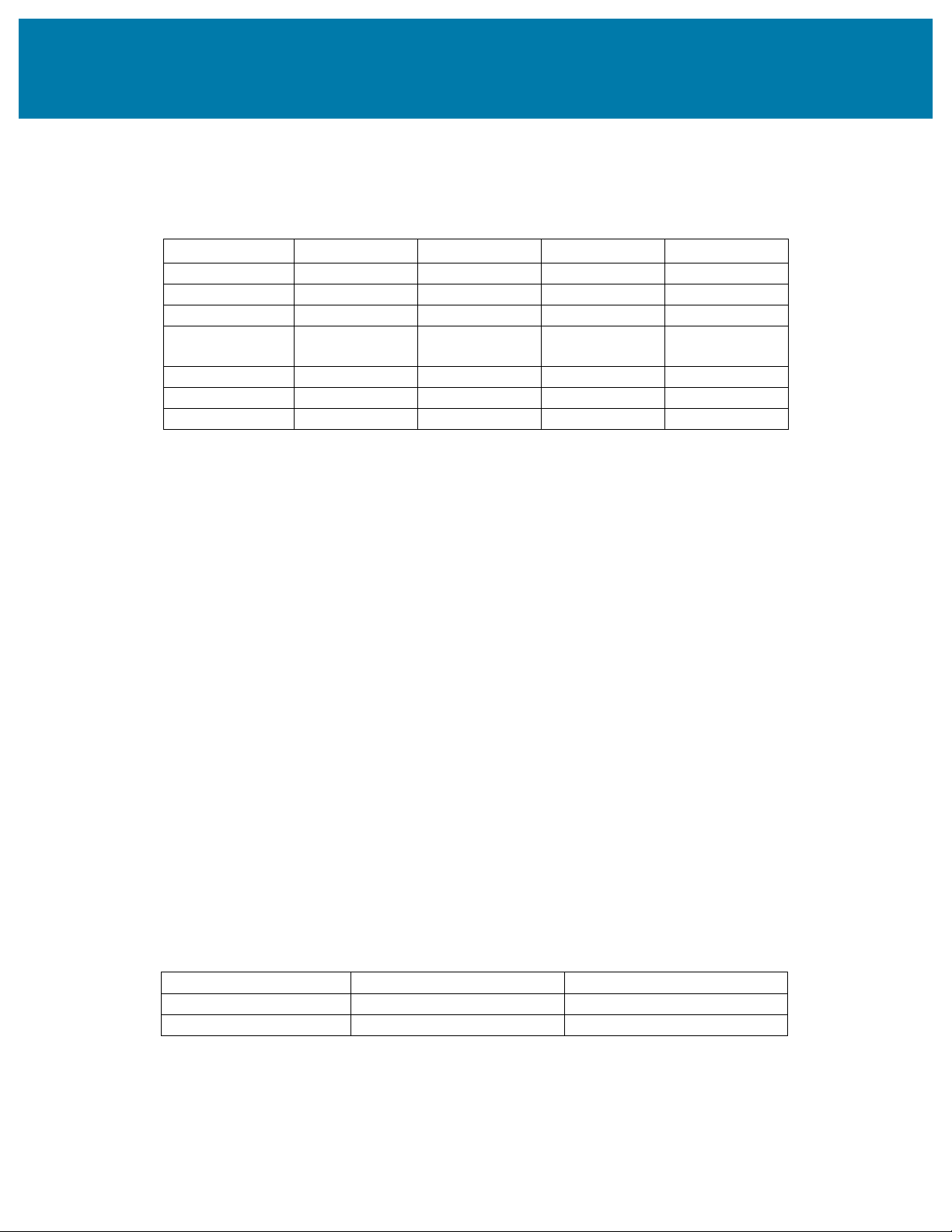
GSM, GPRS, EDGE, UMTS and UMTS evolutions are shown in Table 1.1. Standard 3GPP Release Year
Peak DL Speed Peak UL Speed GSM Release 96 1997 43.2 kbps 14.4 kpps GPRS Release 97 1998 80 kbps 40 kbps EDGE Release 98 1999 296 kbps 118.4 kbps UMTS WCDMA Release 99 2000 384 kbps 384 kbps (FDD and TDD) HSDPA Release 5 2002 1800 kbps 384 kbps HSUPA Release 6 2004 3.6-7.2 Mbps 5.76 Mbps HSPA+ Release 7 and 8 2007/2008 28-42 Mbps 11.5 Mbps
Table 1.1 Performance Evolution of 3GPP standards
Table 1.1 shows that the initial UMTS network deployment was based on 3GPP Release 99 specifications, which
included voice and data capabilities. 3GPP Release 5 introduced High Speed Downlink Packet Access (HSDPA) in
2002. HSDPA used higher order modulation schemes (16-QAM) to downlink transmissions but did not modify the
uplink. In 2004, 3GPP Release 6 introduced Enhanced Up Link (UL) - also referred to as High Speed UL Packet
Data Access (HSUPA). HSUPA improved data rates through more efficient spectrum utilization and lower latency.
The combination of HSDPA and HSUPA technologies is referred to simply as High Speed Packet Access (HSPA).
The next evolution of the UMTS standard was HSPA evolution, which is also known as HSPA+ or evolved HSPA.
HSPA+ brings improved support and performance for real-time conversational and interactive services such as push-
to-talk over cellular, picture and video sharing, and video and voice over internet protocol (VoIP). HSPA+ was first
introduced in 2007 with 3GPP Release 7, though the HSPA+ term is used to describe new features introduced in all
later versions of the UMTS standard (3GPP Release 7 and later). HSPA+ introduced new downlink features
including the 64-QAM modulation scheme and multiple-input-multiple-output (MIMO) antenna technology. In the
uplink, HSPA+ added the 16-QAM modulation scheme. The standardization of HSPA+ has continued through to
Release 11 and continues to push HSPA peak data rates. In fact, future releases of the UMTS standard will likely
utilize some of the techniques developed for Long Term Evolution (LTE) - extending the life of UMTS networks.
2. Overview of the UMTS Standard
The UMTS and WCDMA specifications are a joint standardization project of Europe, Japan, Korea, USA and China.
As a result, UMTS allows both Frequency Division Duplex (FDD) and Time Division Duplex (TDD) for operating
with paired and unpaired bands respectively. The possibility to operate in either FDD or TDD mode allows for
efficient utilization of the available spectrum and depends on a wide range of regionally-varying spectrum scenarios.
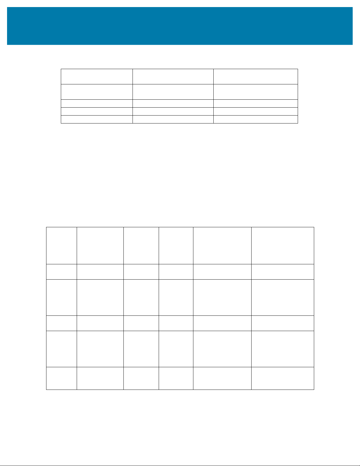
The key differences between UMTS FDD and TDD are outlined in Table 2.1. Parameter UMTS-TDD UMTS FDD Multiple access method TDMA, CDMA CDMA Duplex method TDD FDD lOMoAR cPSD| 58977565
Introduction to UMTS Device Testing
Transmitter and Receiver Measurements for WCDMA Devices Channel spacing 1.6 MHz, Typical 5 MHz 5 MHz, Optional Carrier chip rate 1.28 Mcps, Typical 3.84 Mcps 3.84 Mcps, Optional Frame length 10 ms 10 ms Detection Coherent based on midamble
Coherent based on pilot symbols Spreading factors 1 .. 16 4 .. 512
Table 2.1 Differences and Similarities Between UMTS TDD and FDD
Table 2.1 shows that the physical layer transmissions are quite similar between TDD and FDD modes – although
this document will mainly focus only on testing for FDD. The chip rate of 3.84 Mcps produces a transmission
bandwidth of approximately 5 MHz. DS-CDMA systems with a bandwidth of about 1 MHz, such as IS-95, are
commonly referred to narrowband CDMA system. The inherently wide bandwidth of WCDMA supports higher user data rates.
Bands and Frequency Definitions
The radio interface of UMTS is known as the UMTS Terrestrial Radio Access (UTRA) and the 3GPP defines a
number of paired frequency bands in which a UMTS terminal can operate. The operating bands are specified
according to the center frequency at which the user equipment (UE) either transmits or receives data. These bands
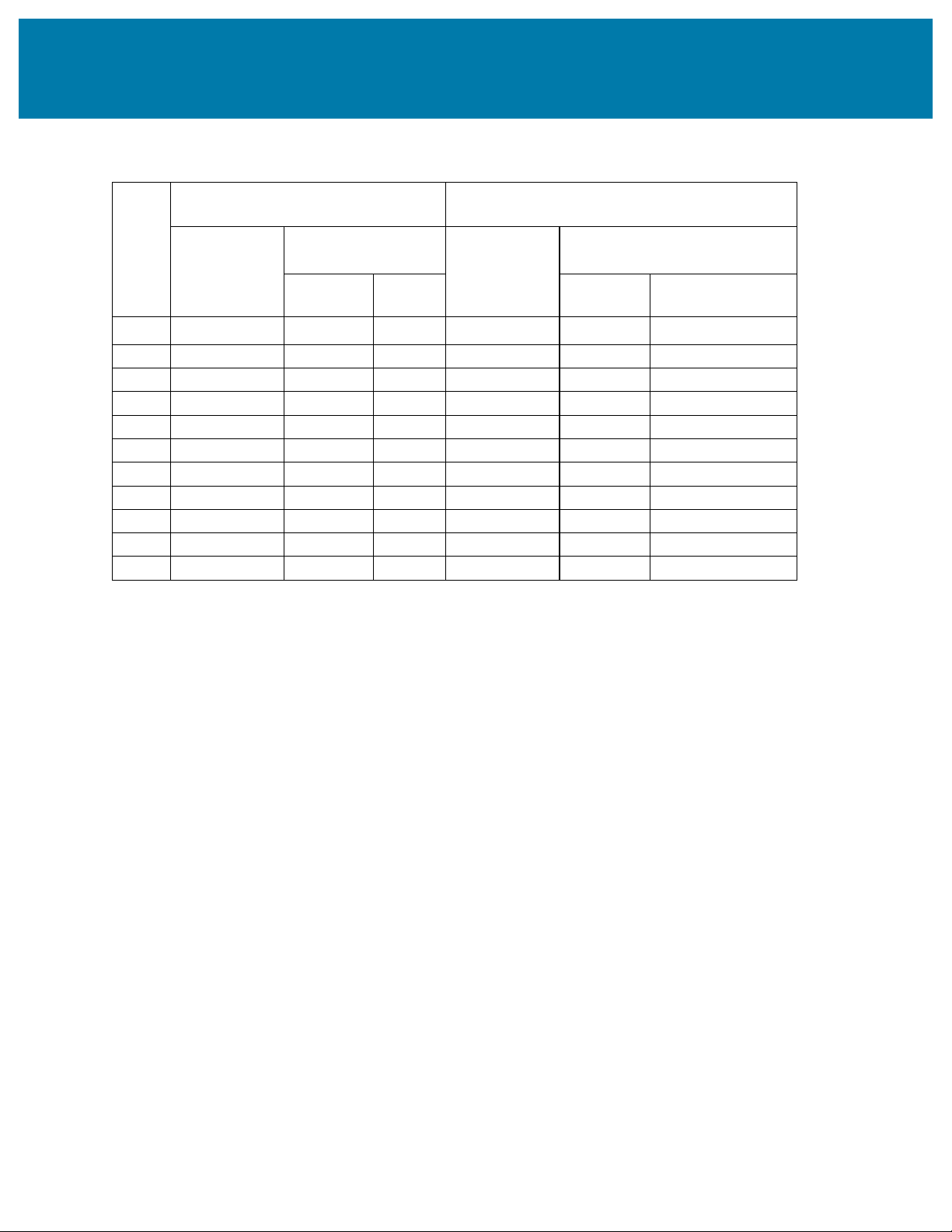
are described in Table 2.2.
Operating UL Frequencies DL TX-RX ARFCN Range UL ARFCN Range DL Band UE transmit,
frequencies frequency
Node B receive UE receive, separation Node B transmit 2110 - 2170 I 1920 - 1980 MHz 190 MHz 9612 to 9888 10562 to 10838 MHz 9262 to 9538 9662to 9938 additional additional 12, 37, 62, 1930 - 1990 412, 437, 462, 487, 512, II 1850 -1910 MHz 80MHz 87, 112, 137, 162, MHz 187, 212, 237, 262, 537, 562, 587, 612, 637, 287 662, 687 1805 - 1880 III 1710 -1785 MHz 95 MHz 937 to 1288 1162 to 1513 MHz 1312 to 1513 1537 to 1738 additional additional 1662, 1687, 2110 - 1887, 1912, 1937, 1962, IV 1710 -1755MHz 400 MHz 1712, 1737, 1762, 2155MHz 1787, 1812, 1837, 1987, 2012, 2037, 2062, 2087 1862 4132 to 4233 4357 to 4458 additional 869 - V 824 - 849MHz 45 MHz
additional 782, 787, 1007, 1012, 1032, 1037, 894MHz 807, 812, 837, 862 1062, 1087 lOMoAR cPSD| 58977565
Introduction to UMTS Device Testing
Transmitter and Receiver Measurements for WCDMA Devices 875 - 885 4162 to 4188 4387 to 4413 additional VI 830 - 840 MHz 45 MHz MHz additional 812, 837 1037, 1062 2012 to 2338 2237 to 2563 additional
additional 2362, 2387, 2587, 2612, 2637, 2662, 2620 - 2690 2412, 2437, 2462, 2687, 2712, 2737, 2762, VII 2500 - 2570 MHz 120 MHz MHz 2487, 2512, 2537, 2787, 2812, 2837, 2862, 2562, 2587, 2612, 2887, 2912 2637, 2662, 2687 925 - 960 VIII 880 - 915 MHz 45 MHz 2712 to 2863 2937 to 3088 MHz 1749.9 - 1784.9 1844.9 - IX 95 MHz 8762 to 8912 9237 to 9387 MHz 1879.9 MHz 2887 to 3163
additional 3187, 3212, 3112 to 3388 additional 2110 - 2170 3237, 3262, 3287, 3412, 3437, 3462, 3487, X 1710 - 1770 MHz 400 MHz MHz 3312, 3337, 3362, 3512, 3537, 3562, 3587, 3387, 3412, 3437, 3612, 3637, 3662, 3687 3462 1427.9 - 1447.9 1475.9 - XI 48 MHz 3487 to 3562 3712 to 3787 MHz 1495.9 MHz
Table 2.2 3GPP Designated FDD Frequency Bands for UTRA
A typical handset supports a certain subset of the bands in Table 2.2 depending on the desired market, since
supporting all would be challenging for the transceiver especially for front-end components such as power
amplifiers, filters, duplexers, and antennas. As a result of the band allocations illustrated in Table 2.2, the frequency
spacing between uplink and downlink bands varies according to the bands supported by the device. Although the
UMTS standard was original designed with bands I and II, subsequent 3GPP releases have defined additional bands.
In all bands, the nominal channel spacing is 5 MHz with each channel’s center frequency an inter multiple of 200
kHz, but this can be adjusted to optimize performance in a particular deployment scenario by a minimum of 4.4
MHz. Channel numbers can be defined by the UTRA Absolute Radio Frequency Channel Number (UARFCN). For
each operating band, the values of the UARFCN are defined in Equation 2.1 and Equation 2.2.
NU = 5 x (FUL - FUL_Offset), for the carrier frequency range FUL_low ≤ FUL ≤ FUL_high
Equation 2.1. Uplink UARFCN as a Function of Frequency Band
ND = 5 x (FDL - FDL_Offset), for the carrier frequency range FDL_low ≤ FDL ≤ FDL_high
Equation 2.2. Downlink UARFCN as a Function of Frequency Band
In Equation 2.1 and Equation 2.2, NU and ND are the UARFCN for the uplink and the downlink. For example,
consider the UARFCN calculation for channels in operating band II in North America. In order to calculate
UARFCN, you must first determine characteristics such as the high and low uplink and downlink frequencies as
specified in Table 2.3. lOMoAR cPSD| 58977565
Introduction to UMTS Device Testing
Transmitter and Receiver Measurements for WCDMA Devices UPLINK (UL) DOWNLINK (DL)
UE transmit, Node B receive
UE receive, Node B transmit UARFCN Carrier frequency UARFCN Carrier frequency
Band formula offset (F formula offset
UL) range [MHz]
(FDL) range [MHz]
FUL_Offset [MHz] FUL_low
FUL_high FDL_Offset [MHz] FDL_low FDL_high I 0 1922.4 1977.6 0 2112.4 2167.6 II 0 1852.4 1907.6 0 1932.4 1987.6 III 1525 1712.4 1782.6 1575 1807.4 1877.6 IV 1450 1712.4 1752.6 1805 2112.4 2152.6 V 0 826.4 846.6 0 871.4 891.6 VI 0 832.4 837.6 0 877.4 882.6 VII 2100 2502.4 2567.6 2175 2622.4 2687.6 VIII 340 882.4 912.6 340 927.4 957.6 IX 0 1752.4 1782.4 0 1847.4 1877.4 X 1135 1712.4 1767.6 1490 2112.4 2167.6 XI 733 1430.4 1445.4 736 1478.4 1493.4
Table 2.3 UARFCN Definition 1 1 3GPP TS 34.121, Section 4.4
Table 2.3 shows that channels in Band II have the following definitions: FUL_Offset = FDL_Offset = 0 FUL_low =1852.4 MHz FUL_high =1907.6 MHz FDL_low = 1932.4 MHz FDL_high = 1987.6 MHz
You can calculate the corresponding UARFCN number (NU) for uplink and downlink channels based on center
frequency by applying Equation 2.1 and Equation 2.2. For example, an uplink transmission at a center frequency
of 1852.4 MHz would have the following UARFCN definition:
NU = 5 x (1852.4 MHz - 0) = 9262 lOMoAR cPSD| 58977565
Introduction to UMTS Device Testing
Transmitter and Receiver Measurements for WCDMA Devices
Similarly, a downlink transmission at a center frequency of 1987.6 MHz would have the following UARFCN definition:
NU = 5 x (1987.6 MHz - 0) = 9938
You can use Equation 2.1 and Equation 2.2 to calculate the UARFCN number for any channel.
Wideband Code Division Multiple Access Technology
Spread spectrum communication systems have been in existence for decades. They are used in areas where the need
for signals displaying anti-jam and low probability-of-intercept characteristics is paramount. Thus, they have been
typically designed to be wideband, and those that employed direct sequence (DS) to achieve multiple access
capability were the original forerunners of WCDMA. CDMA is based on direct sequence spread spectrum (DSSS),
which utilizes a unique “spreading code” and applies it to a transmitted signal. In a spread spectrum system, the
processing gain is the ratio of the spread bandwidth to the unspread bandwidth, which can be calculated using Equation 2.3 below.
𝐶ℎ𝑖𝑝 𝑟𝑎𝑡𝑒
𝑃𝑟𝑜𝑐𝑒𝑠𝑠𝑖𝑛𝑔 𝑔𝑎𝑖𝑛 =10 log 𝐵𝑖𝑡 𝑟𝑎𝑡𝑒
Equation 2.3. Processing Gain of a CDMA Signal.
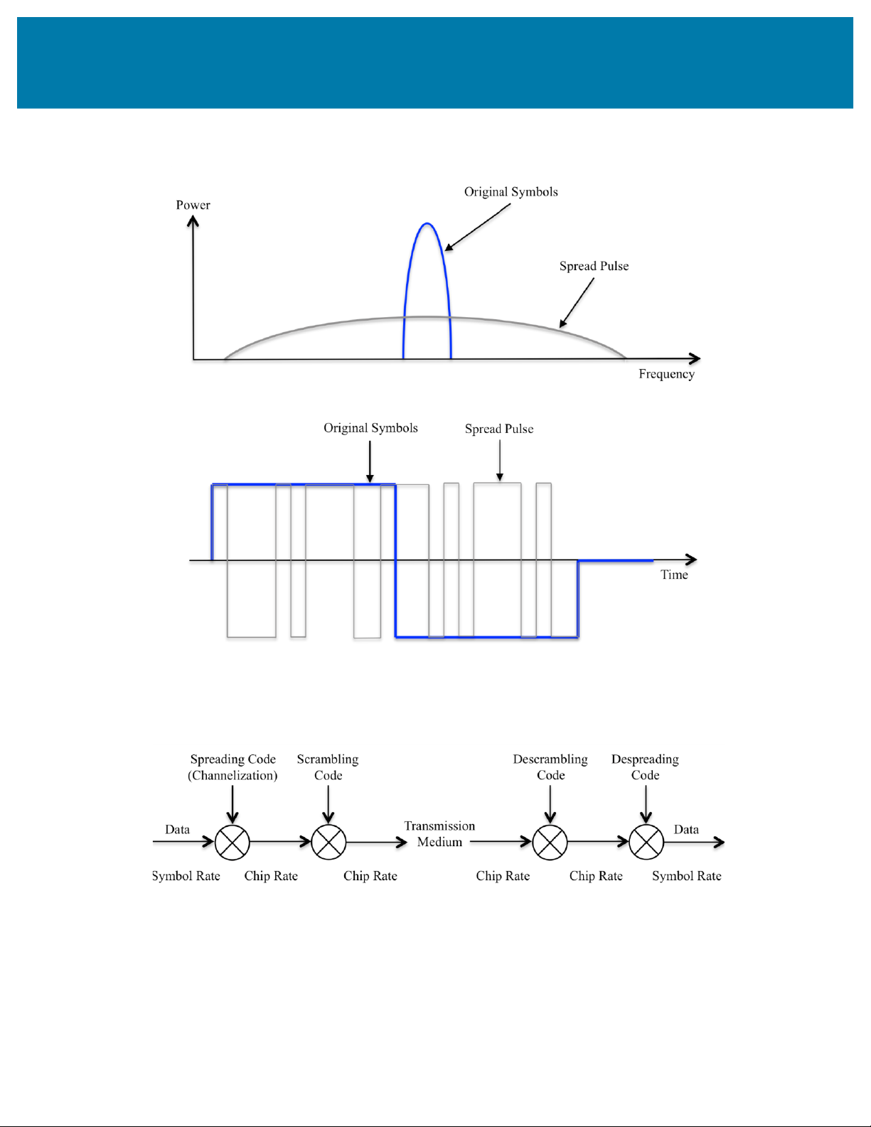
Although the spreading code increases the bandwidth of the transmission, it also enables the channelization of the
transmission. Figure 2.1 shows that applying a spreading code spreads the signal in the frequency domain and as a
result, we refer to DSSS and CDMA as spread spectrum techniques. lOMoAR cPSD| 58977565
Introduction to UMTS Device Testing
Transmitter and Receiver Measurements for WCDMA Devices
Figure 2.1. CDMA in the Time and Frequency Domain.
In order to demodulate a CDMA transmission, the receiver applies the same spreading code used in the transmission
in order to demodulate the signal. This is illustrated in Figure 2.2. lOMoAR cPSD| 58977565
Introduction to UMTS Device Testing
Transmitter and Receiver Measurements for WCDMA Devices
Figure 2.2. Processing of a CDMA signal
Applying spread spectrum modulation techniques to cellular communications allows for multiple users to share
common spectrum. In addition, the transmitter encodes each channel in such a way that a decoder with the
spreading code can pick out the wanted signal from other signals using the same band.
Channelization codes used in UMTS are based on orthogonal variable spreading factor (OVSF) techniques for
downlink transmission. The use of OVSF codes allows for the use of spreading codes of varying lengths while still
allowing for orthogonality between each spreading code. Because the spreading code length is variable, the base
station can therefore adjust the robustness of the transmission according to the channel conditions. For example, a
shorter spreading code (with lower robustness but higher data rates) might be desirable for a handset that is close to
the base station. By contrast, a longer spreading code (with higher robustness and lower data rates) might be
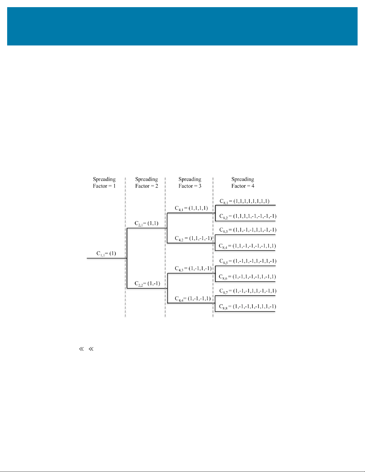
desirable for a handset that is farther from the base station. The code tree in Figure 2.3 defines the OVSF codes.
Figure 2.3. Code tree for generation of orthogonal variable spreading factor (OVSF) codes
Figure 2.3 uniquely describes the channelization codes as CSF,k, where SF is the spreading factor of the code andk is the
code number, 0 k SF-1. Each level in the code tree defines channelization codes for a given spreading factor; a code in
the tree is orthogonal to all other codes except for those that are below it.
Synchronization between each channel is required to preserve orthogonality between each channel. While
synchronization is easy to achieve in the downlink, because all channels are transmitted by a common radio, this is
not the case in the uplink. In the uplink, challenges with synchronizing receivers and varying distances from the
handset to the base station make channel synchronization much more challenging. As a result, uplink transmissions lOMoAR cPSD| 58977565
Introduction to UMTS Device Testing
Transmitter and Receiver Measurements for WCDMA Devices
are designed such that base stations can still demodulate the transmissions even if transmissions between multiple handsets are not orthogonal. Power Statistics
Finally, observe that that the number of channels supported in a downlink transmission has a significant impact on
the peak to average power ratio (PAPR) of the signal. For example, transmissions with a large number of channels
will produce a scenario where power from each channel will constructively or destructively interfere. Thus,
transmissions with a large number of channels with have a higher PAPR than those with a small number of channels.
Table 2.5 compares PAPR characteristics of a wide range of downlink signal configurations. Signal Type Typical PAPR (dB) Test Model 1 (4 DPCH) 10.8 Test Model 1 (64 DPCH) 11.5 Test Model 2 9.2 Test Model 3 (32 DPCH) 12.7
Table 2.5 PAPR of Various UMTS Downlink Test Signals
Table 2.5 illustrates that the number of channels and the modulation scheme both have a significant impact on the
PAPR of the downlink waveform.
Modulation Schemes
Modern implementations of UMTS use various modulation schemes to vary the data rate of a physical channel.
Transmissions defined by the UMTS standard originally used the QPSK modulation scheme. However, demands for
higher data rates pushed future revisions of the standard to higher order modulation schemes. In 2002, 3GPP Release
5 introduced High Speed Down Link (DL) Packet data Access (HSDPA). This evolution introduced the 16-QAM
modulation scheme to downlink transmission, although it still used QPSK for uplink transmissions. Figure 2.5
illustrates a constellation diagram for a 16-QAM symbol map. lOMoAR cPSD| 58977565
Introduction to UMTS Device Testing
Transmitter and Receiver Measurements for WCDMA Devices
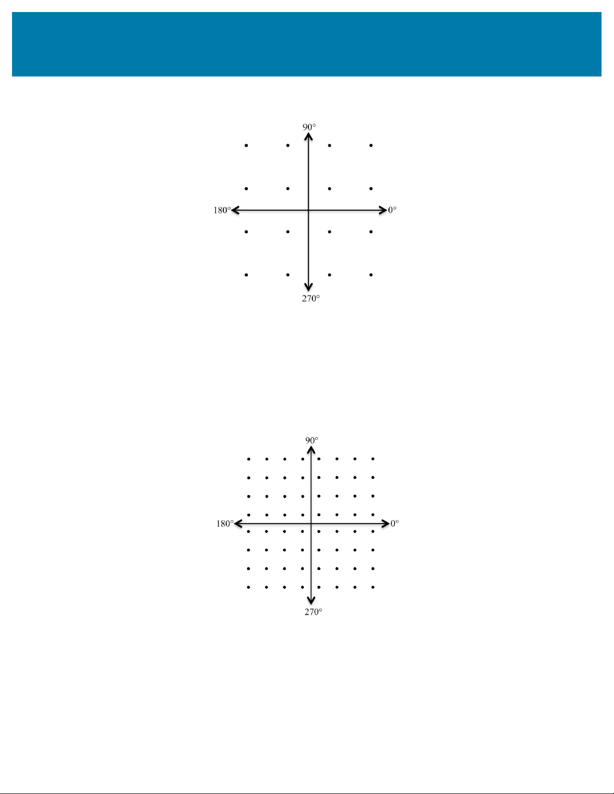
Figure 2.5. Constellation Diagram of 16-QAM
Figure 2.5 shows that 16-QAM uses 16 discrete combinations of phase and magnitude to represent digital data. The
16-QAM scheme is capable of 4 logical bits per symbol.
3GPP Release 7, also known as HSPA+, introduced 16-QAM to the uplink transmissions and 64-QAM to the
downlink. 64-QAM utilizes 64 discrete combinations of phase and magnitude, and each symbol represents 6 logical
bits. Figure 2.6 illustrates a constellation diagram for a 64-QAM symbol map.
Figure 2.6. Constellation Diagram of 64-QAM.
Table 2.6 illustrates which modulation schemes are supported in various 3GPP releases. lOMoAR cPSD| 58977565
Introduction to UMTS Device Testing
Transmitter and Receiver Measurements for WCDMA Devices Peak DL Peak UL Standard 3GPP Release Notes
Modulation Modulation UMTS Release 4 QPSK QPSK Commonly referred to as WCDMA HSDPA Release 5 16-QAM QPSK HSUPA Release 6 16-QAM QPSK HSPA+ Release 7 64-QAM 16-QAM Downlink MIMO HSPA+ Release 8 and Later 64-QAM 16QAM
Carrier Aggregation in Release 9
Table 2.6. Performance Evolution of 3GPP Standards
Later revisions of the UMTS standard such as 3GPP Release 7 and later also allow for a base station and handset to
use multiple concurrent channels, which is known as carrier aggregation. Carrier aggregation, in addition to the
inclusion of 2x2 MIMO in Release 7, enable substantially higher data rates than the original UMTS specification.
MIMO and Carrier Aggregation
Starting with 3GPP Release 7, multiple-input-multiple-output (MIMO) and carrier aggregation are key features of
HSPA+ that allow for continued increase in transmission data rates. MIMO increases the overall data rate through
the transmission of two or more unique data streams through multiple antennas. This process, known as spatial
multiplexing, uses the same channelization codes at the same time.
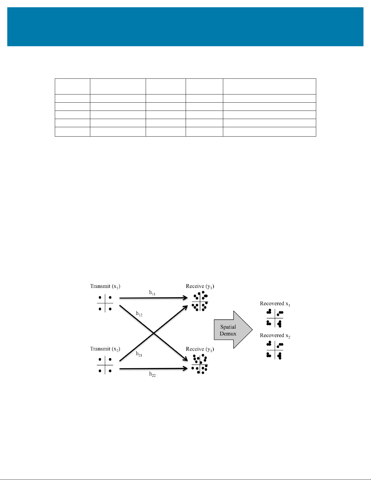
Figure 2.7illustrates that MIMO schemes enable the transmission of unique data streams on different antennas at the
same time. In theory, the transmissions would seem to interfere with one another. However, through of combination
multiple receive antennas and knowledge of the channel, the receiver is able to reconstruct each of the unique
transmissions and demodulate them independently. As a result, a 2x2 MIMO system with two transmit and two
receive antennas is theoretically capable of a double the bandwidth scheme with only 1 transmit and 1 receive antenna. lOMoAR cPSD| 58977565
Introduction to UMTS Device Testing
Transmitter and Receiver Measurements for WCDMA Devices
Figure 2.7. Simplified 2x2 MIMO Using Spatial Multiplexing
HSPA+ allows for up to two transmit and two receive antennas for a 2x2 MIMO configuration in the downlink.
Note, however, that in 3GPP Release 7, MIMO cannot be used in combination with the 64-QAM modulation
scheme. Use of 64-QAM in conjunction with 2x2MIMO is enabled in Release 8 and later.
The combination of MIMO technology with higher order data rates produces a significant increase in maximum data
rates. For example, Release 7 allows for data rates of up to 28 Mbps with the combination of both 16-QAM and 2x2
MIMO. In addition, Release 8 allows for data rates of up to 42 Mbps with the combination of both 64-QAM and 2x2 MIMO.
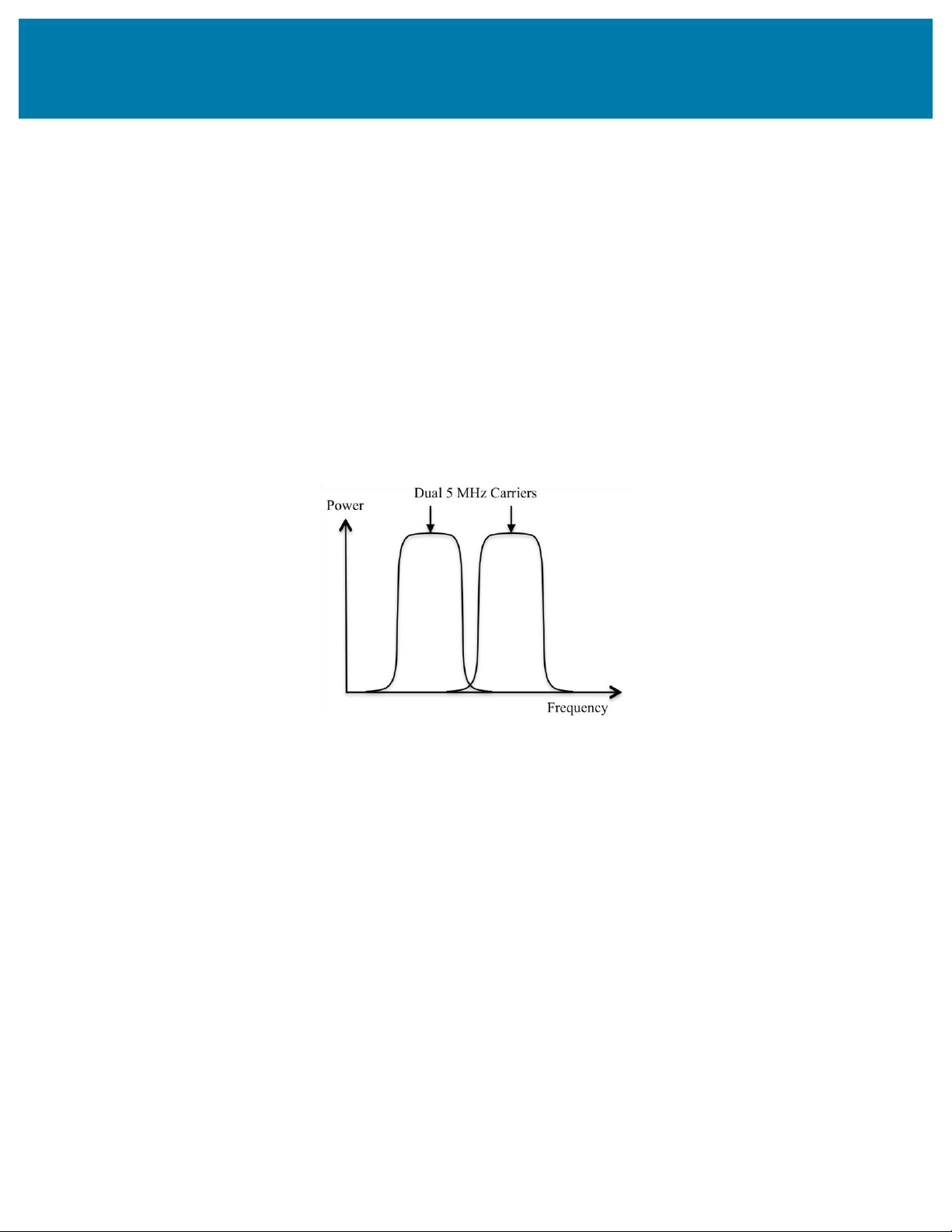
In addition to enhanced MIMO support, Release 8 also adds carrier aggregation to downlink transmissions. In
HSPA, the use of two adjacent carriers in downlink transmission is known as dual cell HSDPA (also referred to as
Dual Carrier-HSDPA or DC-HSDPA). In DC-HSDPA, each of the two carriers is generated in two adjacent 5 MHz
bands, as Figure 2.8 shows.
Figure 2.8 Dual Carriers in DC-HSDPA
The benefit of DC-HSDPA results in increased data transmissions rates, but at the direct expense of larger spectrum
utilization. 3GPP Release 9 extends the carrier aggregation to uplink transmissions as well. Dual-carrier uplink
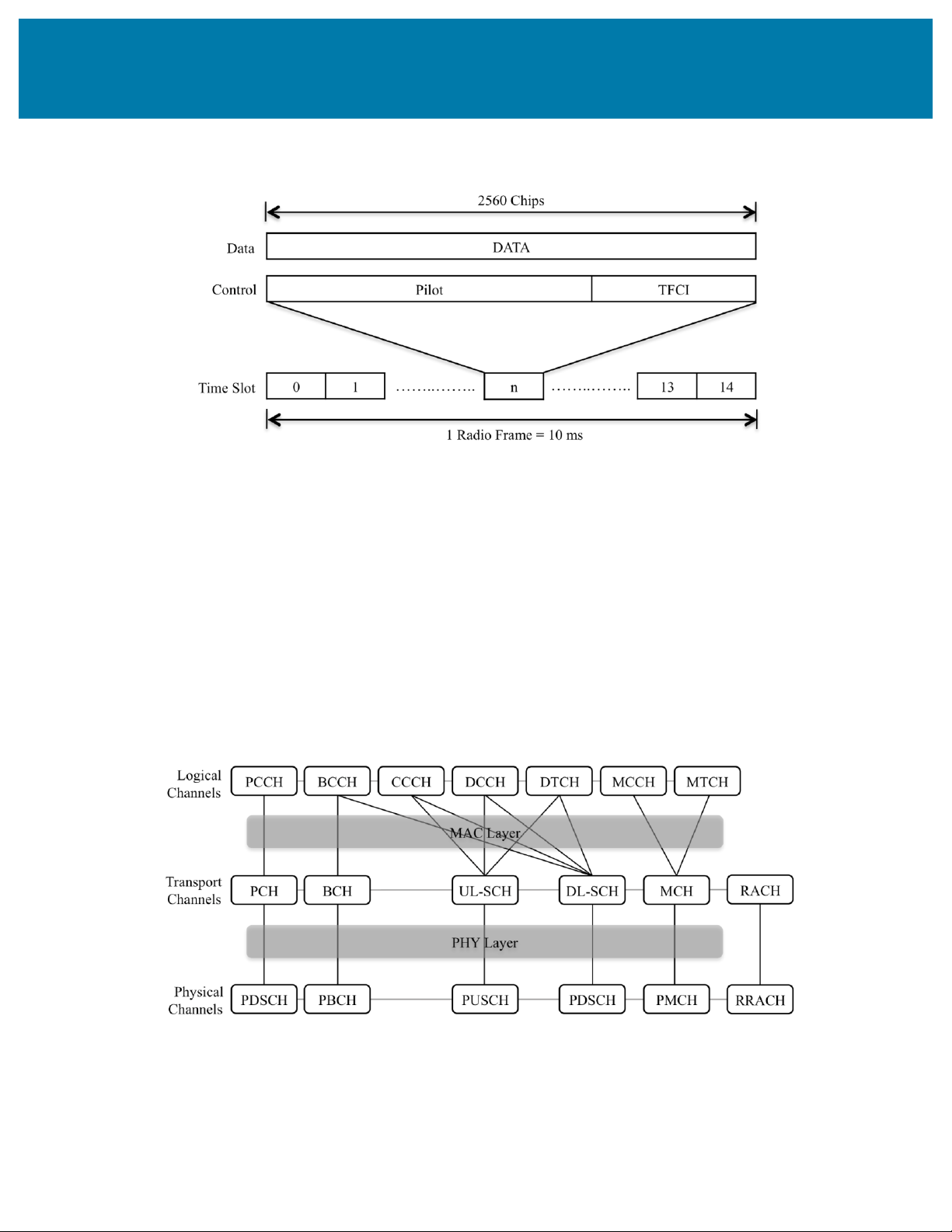
transmissions are known as DC-HSUPA. UMTS Frame Structure
WCDMA transmissions are divided into radio frames and slots. Figure 2.9 shows a 10 ms frame divided into 15
slots (666 us length each). Based on the WCDMA chip rate of 3.84 Mcps, there are 2,560 chips in a time slot and
38,400 chips fit a single radio frame. On the downlink, the time is further subdivided so that the time slots contain
fields that contain either user data or control messages. Figure 2.9 shows the radio frame structure. lOMoAR cPSD| 58977565
Introduction to UMTS Device Testing
Transmitter and Receiver Measurements for WCDMA Devices
Figure 2.9 Radio Frame and Time Slots
The frame is the fundamental unit of time associated with channel coding and interleaving processes. In uplink
transmission, WCDMA uses two different spreading codes to transmit data and control information.
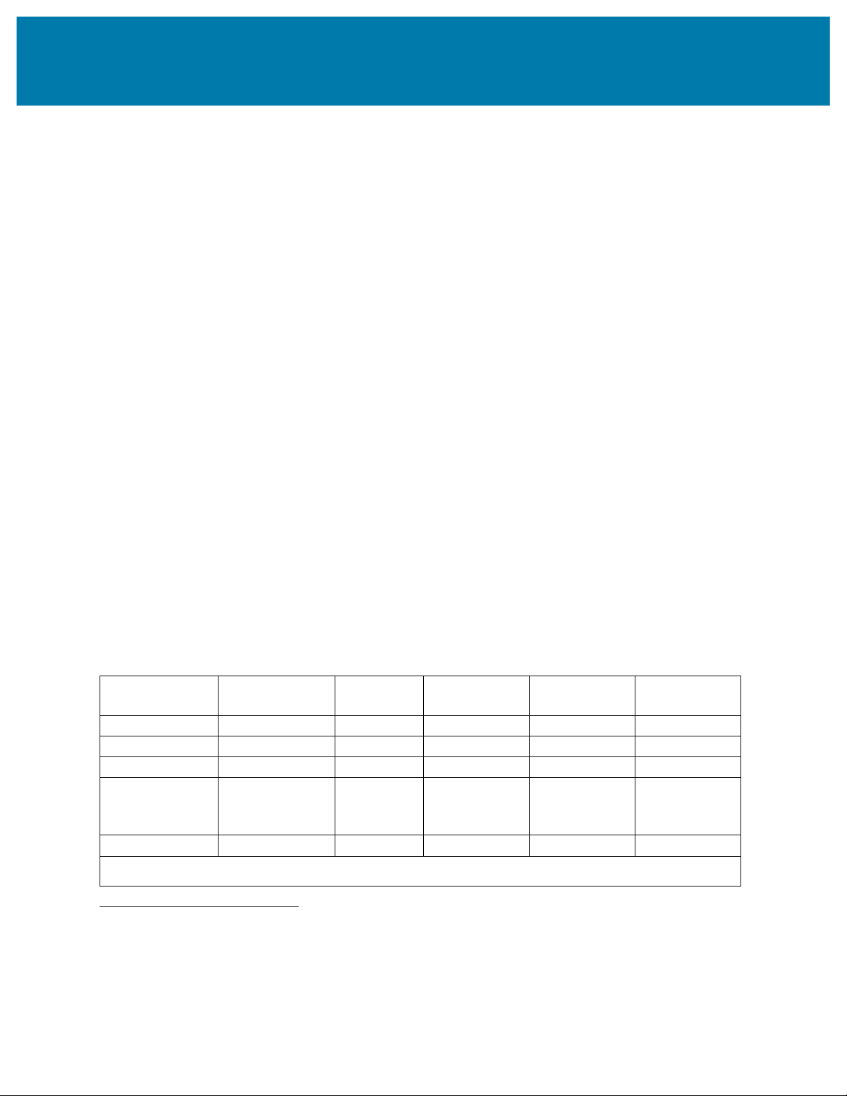
Physical and Logical Channels
Similar to GSM, UMTS defines the notion of logical and physical channels. However, UMTS also adds a new
intermediate channel layer – the transport channel. In UMTS, the physical channels carry the payload data and
govern the physical characteristics of the signal. By contrast, the logical channels define the way in which the data
will be transferred and also serve as a mechanism to categorize the various types of transmissions. Finally, the
transport channels define the way in which the data is transferred and allow for the sharing of resources between the
uplink and downlink. This document primarily describes the physical channels, and does not explicitly explain the
naming conventions of the transport and logical channels. Figure 2.10 shows a graphical representation of the
relationship between each of these layers. lOMoAR cPSD| 58977565
Introduction to UMTS Device Testing
Transmitter and Receiver Measurements for WCDMA Devices
Figure 2.10 Mapping Logical, Transport, and Physical Channels
Figure 2.10 also shows that the nomenclature surrounding the physical, transport, and logical channels of UMTS.
Note that although the nomenclature of these channels is complex, it is important to understand the naming
conventions of the physical channels in order to configure RF test equipment for either transmitter or receiver testing. UMTS Physical Channels
Unlike GSM, which separates physical channels by time slot, physical channels in UMTS are primarily defined by
their unique scrambling/spreading code used in downlink generation1. As a result, the base station is capable of
transmitting multiple physical channels simultaneously through the use of unique codes. Physical channels are
named according to their function and both uplink and downlink transmissions contain multiple physical channels.
In addition, each of these channels can be either dedicated to one particular user or shared between multiple users.
Downlink Physical Channels
In the downlink, there are a wide range physical channels that are either “common” or “dedicated”. The common
downlink physical channels are broadcast to all UEs. By contrast, dedicated channels are intended to be received by
a single UE and no contention for access should occur. Given the wide range of physical channels, it is useful to
understand them in the context of testing UMTS devices. For example, Table 2.7 illustrates various downlink
physical channels that are specifically described by UMTS test model 1. Number of Fraction of Level setting Channelization Timing offset Type Channels Power (%) (dB) Code (x256Tchip) P-CCPCH+SCH 1 10 -10 1 0 Primary CPICH 1 10 -10 0 0 PICH 1 1.6 -18 16 120 S-CCPCH containing PCH 1 1.6 -18 3 0 (SF=256) DPCH (SF=128) 4*/8*/16/32/64 76.8 in total See table 6.2 See table 6.2 See table 6.2
Note*: Only applicable to Home BS 1 ETSI TS 125.211, Section 5 lOMoAR cPSD| 58977565
Introduction to UMTS Device Testing
Transmitter and Receiver Measurements for WCDMA Devices
Table 2.7 Structure of Downlink Test Model 12
As Table 2.7 illustrates, testing UMTS devices requires you to configure test signals that include specific physical
channels. Some of the most important downlink physical channels are described below. •
Primary Common Control Physical Channel (P-CCPCH): The P-CCPCH carries the broadcast
channel, which is a transport channel that carries information about the network and specific cells. •
Primary Common Pilot Channel (CPICH): The CPICH carries a timing reference used by the base
station to enable demodulation by the UE. •
Paging Indication Channel (PICH): The PICH carries a bit mask of reduced paging information to alert
the UE of a forthcoming page message. The PICH allows the handset to sleep more of the time thereby
conserving battery. The PICH does not carry any higher-layer data. •
Secondary Control Physical Channel (S-CCPCH): The S-CCPCH carries several transport channels
including forward access channels (FACH) and the paging channel (PCH). The base station uses the FACH
to relay various information to the UE and uses the PCH to relay message alerts of incoming calls. •
Access Indication Channel (AICH): The AICH indicates the base station's reception of the physical
random access channel (PRACH) preamble, which is an uplink physical channel. •
Dedicated Physical Channel (DPCH): The DPCH carriers both control and data information to the user,
and because of this is possibly the most important of the downlink channels. As Table 2.7shows, each user
is allocated a dedicated DPCH, and test model 1 can be configured to have 4, 8, 16, 32, or 64 channels. The
main benefit of separating control and data information in the DPCH is that higher data rates can be
achieved by simply adding more dedicated physical data channels and still maintaining one dedicated physical control channel.
Although the UMTS standard originally defined test models 1 through 4 for base station testing, 3GPP Release 5
added test models 5 and 6 to account for new physical channels that were added as part of the HSDPA standard.
Physical channels that apply only to HSDPA are given the “HS” qualifier before the physical channel description.
Table 2.8 shows the physical channel naming descriptions. Number of Fraction of Level Setting Channelization Timing offset Type Channels Power (%) (dB) Code (x256Tchip) P-CCPCH+SCH 1 7.9 -11 1 0 Primary CPICH 1 7.9 -11 0 0 PICH 1 1.3 -19 16 120 S-CCPCH containing 1 1.3 -19 3 0 PCH (SF=256)
2 Recreated from Table 6.1 of the ETSI TS 125.151 Specifications lOMoAR cPSD| 58977565
Introduction to UMTS Device Testing
Transmitter and Receiver Measurements for WCDMA Devices DPCH (SF=128) 30/4* 27.1 in total See table 6.6F See table 6.6F See table 6.6F HS-SCCH 2 4 in total See table 6.6G See table 6.6G See table 6.6G HS-PDSCH (64QAM) 8/4* 50.5 in total See table 6.6H See table 6.6H See table 6.6H
Note*: 8 HS-PDSCH shall be taken together with 30 DPCH, and (for Home BS only) 4 HS-PDSCH shall be taken with 4 DPCH
Table 2.8. Test Model 6 Active Channels3
Table 2.8 shows that test model 6 adds two channels, which are discussed below. •
High Speed Shared Control Channel (HS-SSCH): The HS-SSCH provides downlink signaling
information that is specific to HSDPA transmissions. •
High Speed Physical Downlink Shared Channel (HS-PDSCH): The HS-PDSCH is multiplexed both in
time and in code, and is used to carry user data. This channel was introduced in 3GPP Release 5 to carry
QPSK or 16-QAM transmissions, and was updated in 3GPP Release 7 to carry 64-QAM transmissions as well.
Uplink Physical Channels
The two most commonly used dedicated uplink physical channels are the dedicated physical data channel (DPDCH)
and the dedicated physical control channel (DPCCH). •
Dedicated Phyical Data Channel (DPDCH): The DPDCH contains voice or message data from the user to the base station. •
Dedicated Physical Control Channel (DPCCH): The DPCCH contains physical link control information
such as power control bits and the transport format combination indicator.
In addition to dedicated uplink physical channels, uplink transmissions also use shared or common channels. The
most common uplink channels are the Physical Random Access Channel (PRACH) and the Physical Common Packet Channel (PCPCH). •
Physical Random Access Channel (PRACH): The PRACH carries the random access request (RACH)
from the UE to the base station. The UE uses it to request connection to the network as well as for
intermittent services such as low duty cycle packet data.
3 Recreated from Table 6.6E of the ETSI TS 125.151 Specifications lOMoAR cPSD| 58977565
Introduction to UMTS Device Testing
Transmitter and Receiver Measurements for WCDMA Devices •
Physical Common Packet Channel (PCPCH): The PCPCH carries common packet channels and includes
information such as access preambles, collision detection preambles, and power control preambles.
UMTS Physical Layer Testing
Certifying a cellular device for consumer use requires a series of transmitter, receiver, and even compliance
certification. Understanding the physical layer measurements is a critical part not only of the device manufacturing
process, but also the design process. For RF designers who are experienced with GSM systems, WCDMA introduces
several new concepts that affect both the complexity and performance of the measurement system. For example, the
use of more complex modulation schemes such as 64-QAM introduces unique modulation quality metrics and performance characteristics.
Physical layer measurement focuses on the lowest layer of the air interface and determines conformance with the key
parameters essential to the successful transmission of a signal over the air. Transmitter power, modulation quality, and
frequency accuracy of the transmitted signal are all key to a UE’s performance. On the receiver side, the ability of the
UE to successfully decode the received signal at the lowest and highest signal levels defines its operation in the
network. The specifications for both UE and base station performance for UMTS operation are defined by the following specifications: •
3GPP TS 34.121-1: User Equipment (UE) conformance specification; radio transmission and reception
(FDD); Part 1: Conformance specification. •
3GPP TS 34.121-2: User Equipment (UE) conformance specification; radio transmission and reception
(FDD); Part 2: Implementation Conformance Statement (ICS). •
3GPP TS 34.141 – Base station conformance testing specification
The 3GPP WCDMA specifications provide RF conformance criteria to ensure appropriate interoperability between each device.
3. WCDMA Transmitter Measurements
The RF transmitter must be designed in such a way to generate a signal with a given modulation quality while
minimizing interference. The receiver likewise must reliably demodulate a WCDMA signal at relatively low power
levels, while also rejecting a wide range of interference sources. Performance requirements for these RF aspects aim
to ensure that equipment authorized to operate in a WCDMA band meets certain minimum standards.
Similar to GSM transmitter characterization, we can generally divide WCDMA transmitter measurements into the
broad categories of power measurements, spectrum measurements, and modulation quality measurements. Although
the UMTS specifications define these measurements for both the TDD and FDD mode, the measurements are quite
similar between both modes and as a result, this document focuses exclusively on FDD mode. Handset transmitter
measurements are defined by Section 5 of the 3GPP TS 34.121 specifications, as illustrated in Table 3.1. Category Description
3GPP TS 34.121 Section Power
Maximum Output Power 5.2 lOMoAR cPSD| 58977565
Introduction to UMTS Device Testing
Transmitter and Receiver Measurements for WCDMA Devices Measurements
Output Power Dynamics 5.4 Transmit ON/OFF Power 5.5 Occupied Bandwidth 5.8 Spectrum emissions Mask 5.9 Spectrum
Adjacent Channel Leakage Ratio 5.10 Measurements Spurious Emissions 5.11 Transmit Intermodulation 5.12 Modulation Frequency Error 5.3 Quality Transmit Modulation 5.13
Table 3.1. Transmitter measurements of WCDMA
Although the full suite of UMTS transmitter measurements are essential to characterize the performance of a
handset, only a subset of these measurements are relevant when testing RF components, such as power amplifiers
(PAs) or diplexers. In general, only modulation quality (error vector) and spectral measurements (adjacent channel
leakage ratio and spectral emissions mask) are the primary figures of merit for RF components. Because these
measurements describe the influence of non-ideal components, they are excellent metrics for component performance.
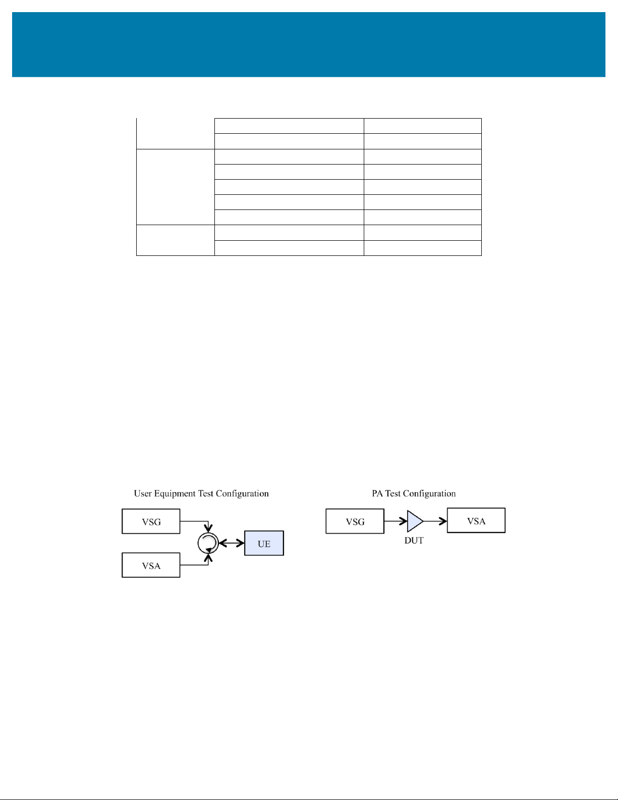
Transmitter Test Setup Configuration
The test and measurement of fully integrated WCDMA handsets typically requires a combination of vector signal
generators (VSGs) and vector signal analyzers (VSAs). When characterizing a WCDMA transmitter, a VSA is the
preferred instrument, because of its ability not only to make modulation quality measurements, but also to make
accurate power and spectrum measurements. When testing these devices, a VSG is also required to source the
modulated signal to the device under test. Two example transmitter test setups are illustrated in Figure 3.1. In the
power amplifier (PA) test configuration, the device under test (DUT) is a PA.
Figure 3.1. Test Setup Configuration for Handset and PA
Figure 3.1 shows that UE test setup requires a circulator to connect both the VSG and VSA to the antenna port.
Tài liệu liên quan:
-
Bài tập quy hoạch mạng hệ thống thu phát vô tuyến môn Thu phát vô tuyến | Học viện Công Nghệ Bưu Chính Viễn Thông
120 60 -
Tài liệu về RF transceiver architectures for W-CDMA systems like UMTS môn Thu phát vô tuyến | Học viện Công Nghệ Bưu Chính Viễn Thông
118 59 -
Tài liệu về Transmit diversity in 3G CDMA systems môn Thu phát vô tuyến | Học viện Công Nghệ Bưu Chính Viễn Thông
119 60 -
Chapter 6 WCDMA môn Thu phát vô tuyến | Học viện Công Nghệ Bưu Chính Viễn Thông
138 69