Đề cương môn Truyền động điện - Trường Đại học bách khoa - Đại học đà nẵng.
In the performed simulation, certain stator flux and torque references are compared to the values calculated in the driver and errors are sending to the hysteresis comparators.Theoutputsofthefluxandtorquecomparators areusedinordertodetermine theappropriatevoltage vector
Đề cương môn Truyền động điện - Trường Đại học bách khoa - Đại học đà nẵng.
Tài liệu gồm 25 trang , giúp bạn tham khảo, ôn tập và đạt kết quả cao.
Môn: Truyền động điện (TDD) 47 tài liệu
Trường: Trường Đại học Bách khoa, Đại học Đà Nẵng 1.7 K tài liệu
Tác giả:

Preview text:
See discussions, stats, and author profiles for this publication at: https://www.researchgate.net/publication/224199155
Performance analysis of Direct Torque Control (DTC) for synchronous
machine permanent magnet (PMSM)
Conference Paper · October 2010
DOI: 10.1109/SIITME.2010.5649125 · Source: IEEE Xplore CITATIONS READS 27 1,188 4 authors: Badre Bossoufi Mohammed Karim
Faculty of Sciences; Sidi Mohamed Ben Abdel ah University
Sidi Mohamed Ben Abdel ah University
194 PUBLICATIONS 2,892 CITATIONS
118 PUBLICATIONS 1,672 CITATIONS SEE PROFILE SEE PROFILE Ahmed Lagrioui Silviu Ionita
National High School of Arts and professions in Meknes (ENSAM) University of Pitesti
63 PUBLICATIONS 1,233 CITATIONS
74 PUBLICATIONS 601 CITATIONS SEE PROFILE SEE PROFILE
Al content fol owing this page was uploaded by Badre Bossoufi on 26 February 2015.
The user has requested enhancement of the downloaded file.
2010 IEEE 16th International Symposium for Design and Technology in Electronic Packaging (SIITME)
Performance Analysis of Direct Torque Control
(DTC) for Synchronous Machine Permanent Magnet (PMSM)
Badre Bossoufi, Mohammed Karim, Ahmed Lagrioui
Badre Bossoufi, Silviu Ioniţă (Membre IEEE)
Laboratory of Data processing, Imagery and Analyzes
Center of Modeling and simulation of the systems, Faculty
Numerical (LIIAN), Faculty of Sciences Dhar El Mahraz.
of Electronics, Communications and Computers, University Fez, Morocco of PITEŞTI
Badre_isai@hotmail.com, karim_lessi@yahoo.fr, PITEŞTI, Romania lagrioui71@gmail.com
Badre_isai@hotmail.com, silviu.ionita@upit.ro
Abstract -- The Direct Torque Control is a technique increasingly
Elimination of rotor position sensor.
used for the ordering of the invertors and synchronous machine.
This system can be regarded as a hybrid dynamic system whose
The amplitude and the frequency of the controlled variables
continuous component is the permanent magnet synchronous
are considered. In the controlling of vector the amplitude and
machine and the discrete component, the inverter of tension. In
the position of a controlled vector of space are considered.
this article, we propose a modeling of this whole by a system with
These reports are valid even during cuts which are essential discrete events. This model is then simulated on
for the precise ordering of couple and speed. Matlab/Simulink.
Keywords- Direct Torque Control (DTC), Permanent Magnet II.
MODELING OF THE SYNCHRONOUS PERMANENT
Synchronous Machine (PMSM). MAGNET MACHINE (PMSM):
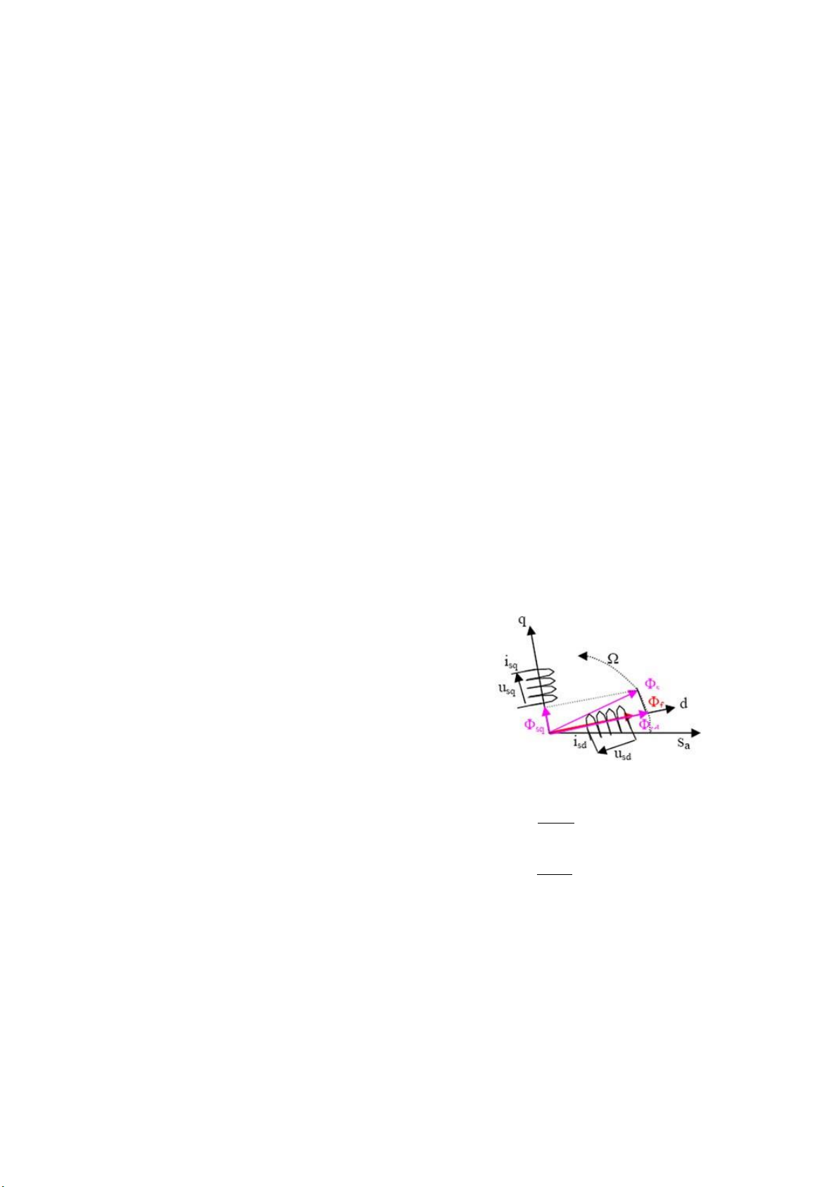
The motor considered in this paper is an interior PMSM I. INTRODUCTION
which consists of a three phase stator windings and a PM rotor.
Permanent magnet synchronous motor drives (PMSM)
The voltage equations in a synchronous reference frame can be
offers many advantages over the induction motor, such as derived as follows,
overall efficiency, effective use of reluctance torque, smaller
losses and compact motor size. In recent years many studies
have been developed to find out different solutions for the
PMSM drive control having the features of quick and precise
torque response, and reduction of the complexity of field
oriented control algorithms [1-3]. The DTC technique has been
recognized as viable and robust solution to achieve these requirements.
In the existing literature, many algorithms have been
suggested for the DTC control [1, 4-6]. The eight voltage-
vector switching scheme seems to be suitable only for high
Figure 1. scheme of the synchronous machine
speed operation of the motor while at low speed the six
voltage-vector switching scheme, avoiding the two zero d
voltage-vectors, seems to be appropriate for the permanent u sd .
sd r .i (1)
magnet synchronous motor drive The voltage vector strategy s sd dt sq
using switching table is widely researched and commercialized, dsq
because it is very simple in concept and very easy to be
u r .i . (2)
implemented. The stator fluxes linkages are calculated from sq s sq
voltage and current models PMSM drive. The DTC is dt sd
increasingly drawing interest because of,
Where the direct and quadrate axis flux linkages are,
Simplicity of its structure.
L .i (3) sd d sd f
Elimination of the current controllers. L .i (4) Inherent delays. sq q sq
978-1-4244-8122-4/10/$26.00 ©2010 IEEE 275
23-26 Sep 2010, Pitesti, Romania
2010 IEEE 16th International Symposium for Design and Technology in Electronic Packaging (SIITME)
The electromagnetic torque of the motor can be evaluated
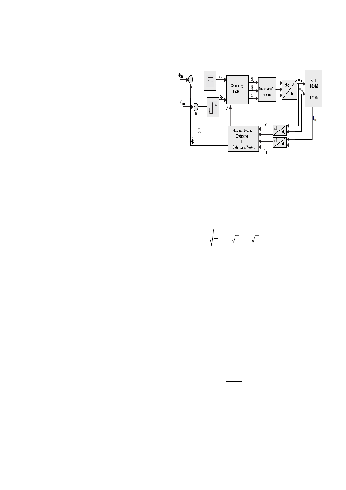
the output states of the hysteresis controller change. Therefore, as follows,
the switching frequency is usually not fixed; it changes with
the rotor speed, load and bandwidth of the flux and torque 3
Ce p.I L ).I controllers. (5) q (Ld q d .I 2 f q
The motor dynamics can be simply described by the equation (6). d Ce C J . f . (6) r dt With:
Ω: rotation's speed mechanical of the PMSM
ω: rotation's speed electric. P: Number of pairs of poles.
J : Total moment of inertia brought back on the tree of the PMSM.
f : Coefficient of viscous friction. Figure 2. Control of DTC C r: Resistive torque.
A. Transformation abc-αβ (Clark):
f: flux produced by the permanent magnet.
As control DTC is a vectorial control, it is necessary to
sd: d axis stator magnetic flux,
have the components of Concordia of the currents and stator
tensions of the PMSM. One thus breaks up the three stator
sq: q axis stator magnetic flux,
currents isabc and the three stator tensions vsabc into components L direct (v
sd: d axis stator leakage inductance,
s) and quadratic (vs) such as: L
sq: q axis stator leakage inductance, x
1 0.5 0.5xsa r s 2 s: stator winding resistance, x (7) x 3 3 sb C 3 0 e: electromagnetic torque, s 2 2 x sc III.
CONTROL DTC (DIRECT TORQUE CONTROL): With x = Vs or is.
Since Depenbrock and Isao Takahashi proposed
Since the model of the PMSM is expressed in the reference
Direct Torque Control for induction machines in the middle of
mark (d-q), a passage of the two-phase system (α -β ) to the
1980's [9, 11], more than one decade has passed. The basic
two-phase system (d-q) (Concordia) proves to be essential:
idea of DTC for induction motor is slip control, which is based
on the relationship between the slip and electromagnetic i cos( ) sin( ) sd is
torque [2]. In the 1990's, DTC for Permanent Magnet . (8)
Synchronous Machines was developed [7, 12, 13]. Compared
isq sin( )
cos( ) is
with Rotor Field Oriented Control, the DTC has many
advantages such as less machine parameter dependence, B. Estimator:
simpler implementation and quicker dynamic torque response. 1) Flux Estimator :
There is no current controller needed in DTC, because it
The stator electric equations of the PMSM, in the reference
selects the voltage space vectors according to the errors of flux mark (α-β) are given by:
linkage and torque. The most common way to carry out the
DTC is a switching table and hysteresis controller, as in [8, d s
14]. Fig. 2 is a typical DTC system. It includes flux and torque V r .i s s s
estimators, flux and torque hysteresis controllers and a dt (9) switching table.
V r .i d s
Usually a DC bus voltage sensor and two output current s s
sensors are needed for the flux and torque estimator. Speed s dt
sensor is not necessary for the torque and flux control. The What:
switching state of the inverter is updated in each sampling time.
Within each sampling interval, the inverter keeps the state until
978-1-4244-8122-4/10/$26.00 ©2010 IEEE 276
23-26 Sep 2010, Pitesti, Romania
2010 IEEE 16th International Symposium for Design and Technology in Electronic Packaging (SIITME) t
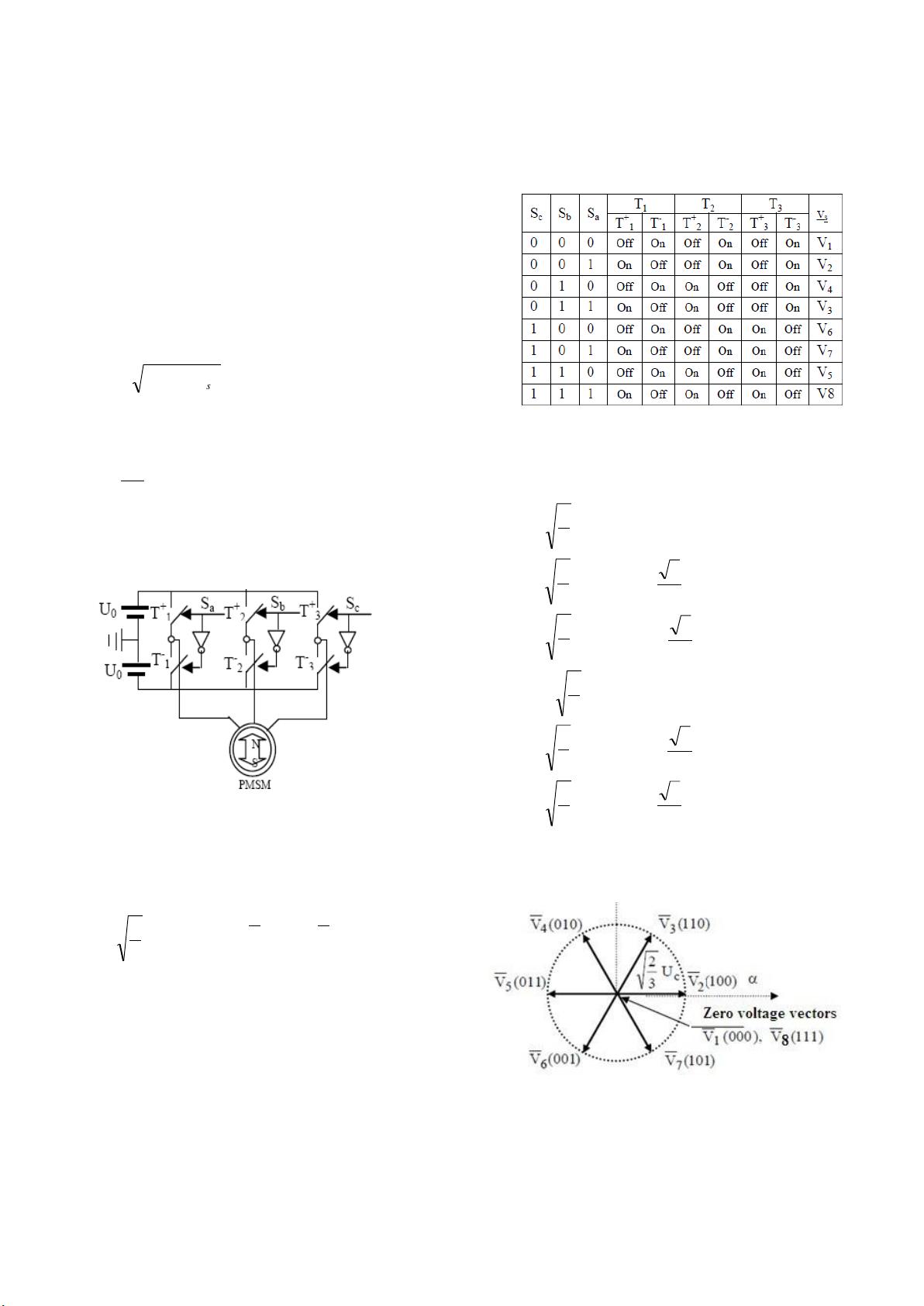
thus 23 = 8 possibilities for the Vs vector. 2 vectors (V1 and ˆ V
(V r .i ).dt
8) correspond to the null vector: (Sa,Sb,Sc) = (0,0,0) et s s s s 0 (S ,S ,S ) = (1,1,1) t a b c ˆ s
(V r .i ).dt (10) s s s
Different configuration from the interrupters 0
ˆ ˆ j.ˆ s s s
For raised speeds, one neglects the voltage drop the equations become:
ˆ t V .dt s s t ˆ t
V .dt (11) s s t 2 s 2 s s 2) Torque Estimator : What:
The electromagnetic couple is given by: 3 p Ce ( .i .i )
V V 0 s s s s (12) 2 1 8
With p: Number of pairs of poles 2 V .U 2 0 3
C. Control switches of the inverter: 2 3 V .U ) 3 0.(0.5 j 3 2 2 3 V .U ) (14) 4 0.(0.5 j 3 2 2 V5 .U 0 3 2 3 V .U ) 6 0.(0.5 j 3 2 V 2 3 .U ) Figure 3. Inverter of tension 0.(0.5 j 7 3 2
The switches of the inverter of tension (Fig.3) must be
ordered so as to maintain the flow and the couple of the
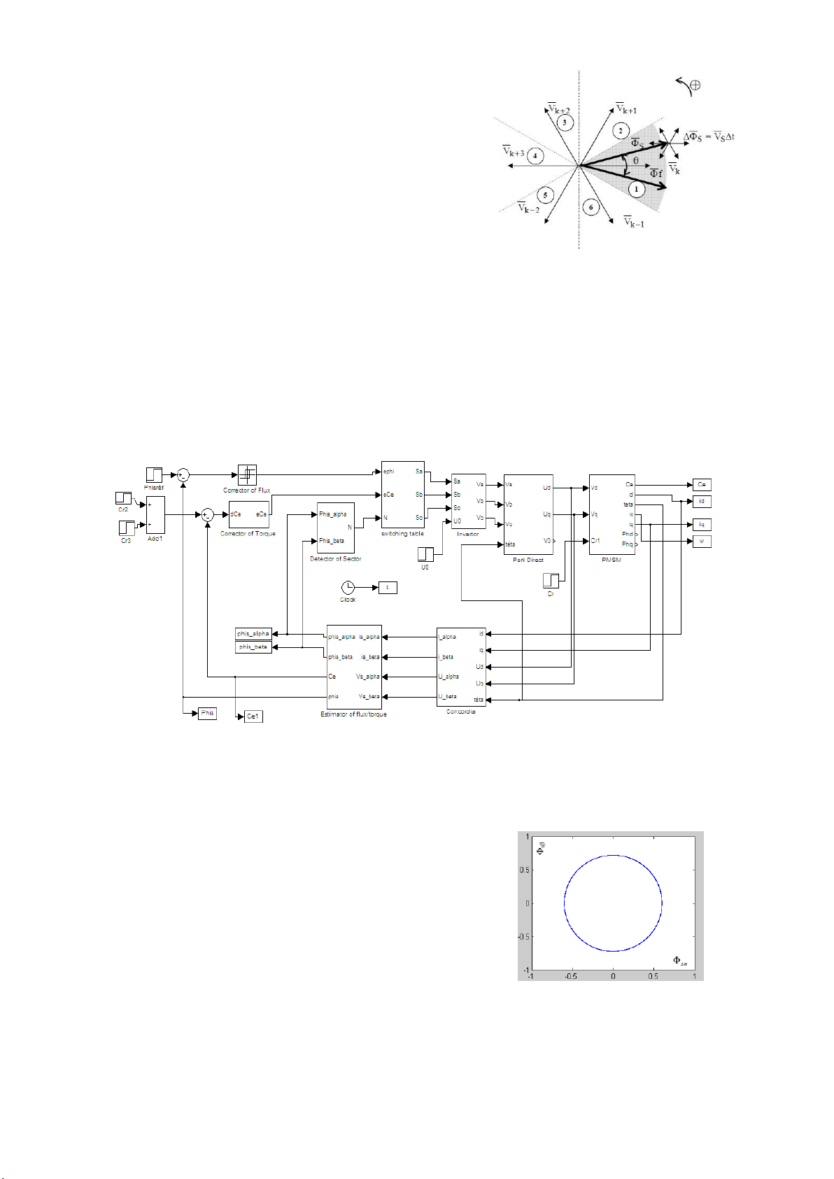
The eight tensions Vi can be represented on the plan
machine. The vector of the stator tension can be written in the complexes as follows: form: 2 4 j j 2 V
.U .(S S .e 3 S .e 3 ) (13) s 0 a b c 3
Where (Sa, Sb, Sc) represent the logical state of the 3
switches: Si = 1 means that the high switch is closed and the
low switch is open (Vi = +U0) and Si = 0 mean that the high
switch is opened and the low switch is closed (Vi = -U0).
One will thus seek to control flow and the couple via
the choice of the vector of tension which will be done by a
configuration of the switches. As we have 3 switches, there are
Figure 4. Vectors tensions and sectors of detection
978-1-4244-8122-4/10/$26.00 ©2010 IEEE 277
23-26 Sep 2010, Pitesti, Romania
2010 IEEE 16th International Symposium for Design and Technology in Electronic Packaging (SIITME)
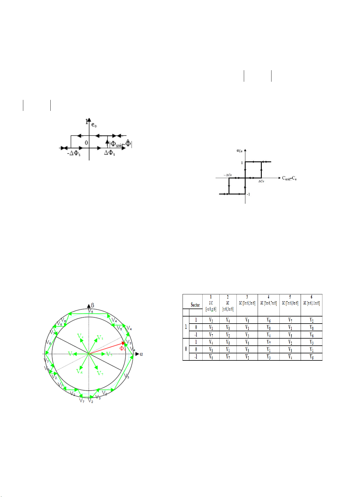
D. Control Vector flux: E. Control Couple:
So as to obtain very good dynamic performances, the
The corrector on three levels. He makes it possible to
choice of a corrector with hysteresis with two navels seems to
control the engine in the two directions of rotation that is to say
be the simplest solution and best adapted to the studied control.
for a positive or negative couple. The exit of the corrector,
Indeed, with this type of controller, one can easily control and
represented by the Boolean variable eCe what must limit the
maintain the end of the vector flux Φs in a circular ring.
couple to a value such as C
Cˆ C , e eref e e Ce can take 3
The exit of the corrector represented by a Boolean variable values:
eΦ (=0 or 1) must indicate if the module of flow must decrease
(eΦ=0) or increase (eΦ=1) by such kind to always maintain
If the error of the couple Ceréf Ce >0, it is necessary to ˆ increase the couple eCe=1 ; sref s
If the error of the couple Ceréf Ce<0, the couple should be decreased eCe=-1 ;
If the error of the couple -∆C e ≤
Ceréf Ce ≤ ∆Ce it is
necessary to keep the same value of the couple
Figure 5. Corrector Flow with Hysteresis on 2 Levels
The practical realization of order DTC is generally done on
charts DSP, FPGA or with microcontrollers having one period
of sampling for the period you to you, the vector tension
chooses does not change what allows, starting from the equation (11), to write: ˆ T
Figure 7. Corrector of the Couple with Hysteresis on 3 levels e
V .dt V .T s s e ˆ 0 s T F. Law of control: e s
V .dt V .T 0 s s e (15)
According to the sector determined by the phase (δ=Arctang(Φ ˆ
β/Φα)) of estimated flow and the evolution ˆ j.ˆ s s s V .T
magnitude of this last as well as the evolution of the estimated s e
couple one can choose the tension Vs to be applied so as to
respect the instructions of flow and the couple. There are thus
The direction of the vector flow Φ s is thus given by the
3 parameters for the choice of vector V selected vector of tension V S, allow choosing the i the figure below shows the adequate vector.
sequence of the vectors tensions maintaining flow in a crown
thickness equal to the width of hysteresis.
In the example of figure 7, flow is in sector 1, If flow Φ s
increases (eΦ=1) and if the couple also increases (eCe=1), the
vector tension to be applied to the PMSM will be V3 this
choice will make it possible to make decrease.
The magnitude of flux Φ s and the couple bus when the
angle of flux Φ s increases (∆w>0) the couple also increase
Figure 6. Sequence of the Vectors Tensions
whereas when (∆w<0) the couple decreases.
978-1-4244-8122-4/10/$26.00 ©2010 IEEE 278
23-26 Sep 2010, Pitesti, Romania
2010 IEEE 16th International Symposium for Design and Technology in Electronic Packaging (SIITME)
If V6 is then selected flow must decrease (eΦ=0) and also couples it (eCe=-1).
If V1 or V8 is selected flow must remain constant (eΦ=
the preceding state) and the couple decreases (e Ce=0).
If V3 is then selected flow must increase (eΦ=1) and also couples it (e Ce=1).
If V7 is then selected flow must increase (e Φ =1) and
the couple must decrease (eCe=-1).
If V4 is then selected flow must decrease (eΦ=0) and
Figure 8. Detection of the Vector Tension when it Vector Flux is Located in the couple must increase (e the Sector Ce=1). IV. SIMULATION AND RESULTS:
A. Diagram of control DTC applied to a PMSM.
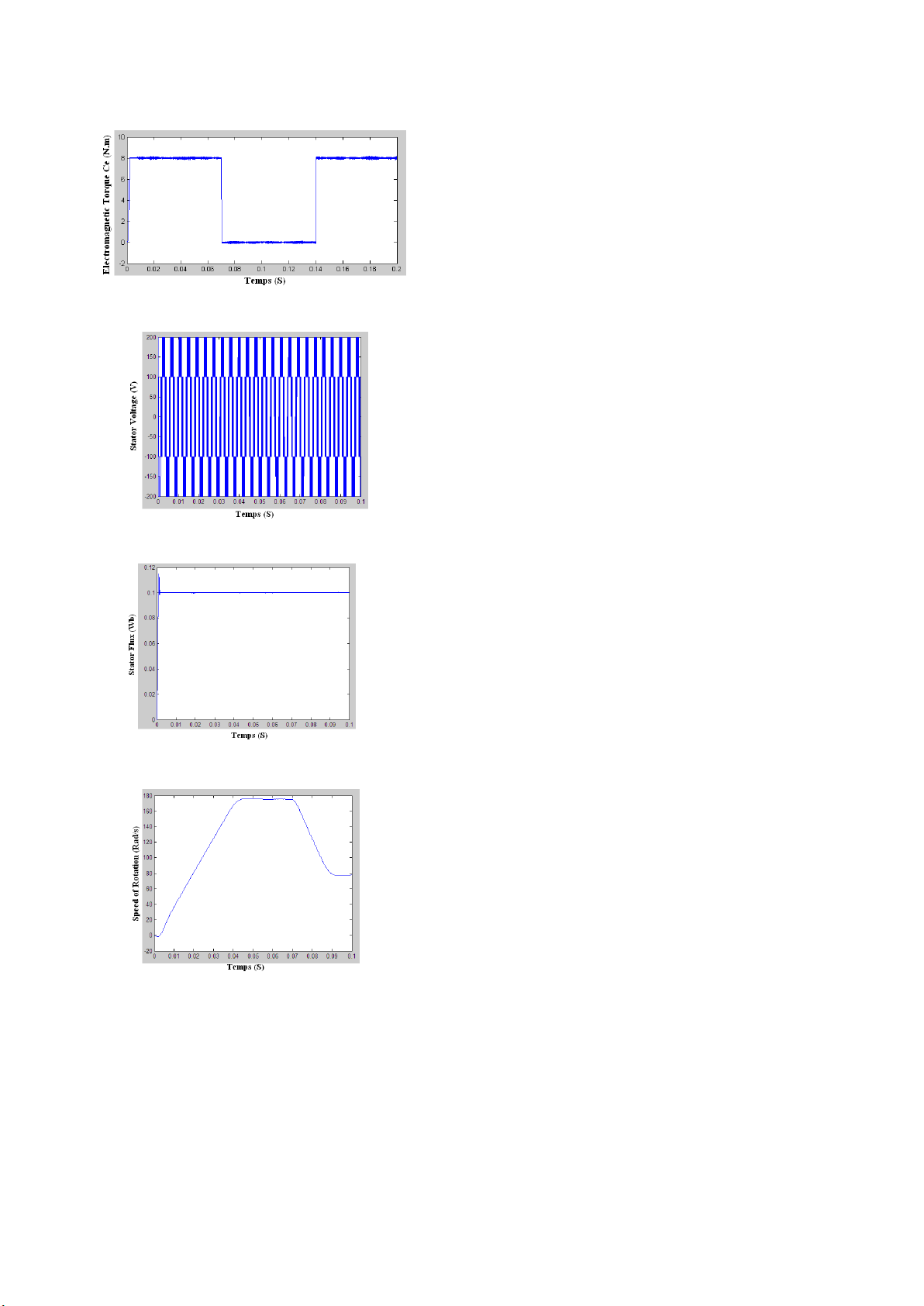
Here the MATLAB/Simulink model of the permanent magnet synchronous motor is developed according to the dq model. In
the simulation, the stator magnetic flux amplitude value is assumed to be the same as the value of the permanent magnet flux. The
inverter dc bus voltage is 300V. Also at t=0.07s, a differential step from 8Nm to 0Nm and at t=0.14s from 0Nm to 8Nm is applied
to the referents torque value. Motor parameters are; p=4, rs=0.4578Ω, Φf=0.171Wb, Lsd=3.34mH, Lsq =3.58mH, J = 0.001469kgm2,
Figure 9 shows the Simulink diagram of the direct torque control for PMSM.
Figure 9. Blocks for the simulation of the DTC under Matlab/Simulink 1) Princip :
and Vsq are applied in average values at the boundaries of
The figure 9 presents the general diagram of the structure
the phases stator of the PMSM.
of the Direct Torque Control DTC of the PMSM in the
2) Results of Simulation:
reference mark dq, the currents isd, isq, Vsd and Vsq are
subjected to the transformation of Clark in order to obtain
the components isα, isβ, Vsα and Vsβ its components are
applied has a block of estimator of couple and flow as well
as the detector of sector, these values estimated thereafter
are compared with values of reference to be included in
correctors of hysteresis to 2 and has 3 levels, to introduce its
errors into a table of commutation which functions by report
sector to generate the impulses of the inverter which will
generate the tension three-phase current thereafter which will
be transformed into co-ordinates dq, the output voltages Vsd
978-1-4244-8122-4/10/$26.00 ©2010 IEEE 279
23-26 Sep 2010, Pitesti, Romania
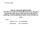
2010 IEEE 16th International Symposium for Design and Technology in Electronic Packaging (SIITME) Figure 10. Trajectory of flux
and stator flux space vector. Vector locations are shown in Figure 10. CONCLUSION:
In this article we presented a modeling under
Matlab/Simulink of unit PMSM, inverter of tension and
order known as DTC. The latter allows uncoupled control
from the torque and flux. This order has the following
advantages: an optimal response time, it controls almost
perfect undulation of the couple and flow, it does not have
mechanical sensors and sensitivity live with screw the
Figure 11. Electromagnetic Torque
variation of certain parameters of the machine, it allows to
obtain excellent dynamic performances. REFERENCES:
[1] [1] : A. Lagrioui, H. Mahmoudi “Modélisation et Simulation de la
commande directe du couple appliquée à une MSAP” ICEE’08, 2008.
[2] [2]: H. Bausch, W.Zeng K.Kanelis B.Lange “Torque Control of
current excited synchronous machines for electric vehicules” ICEMA
proceeding Vol2 septembre 1993.
[3] [3] : I. Boldea N. Muntean “Direct Voltage vector speed control of
surface permanent magnet synchronous motor drives” ICEM proceeding Vol2 septembre1994
[4] [4]: J. Thomas K. René A.A. Melkebeek “Direct Torque Of
Permanent Magnet Synchronous Motors- An Overview” 3RD IEEE – April 2006. Figure 12. Stator voltage (V)
[5] [5] : M. Kadjoudj1, S. Taibi “Modified Direct Torque Control of
Permanent Magnet Synchronous Motor Drives”, IJ-STA, Volume 1,
N° 2, December 2007, pp. 167−180.
[6] [6] : Carlos Canudas de Wit « Modélisation contrôle vectoriel et DTC
» , HERMES Science Europe Ltd,2000.
[7] [7]: M. W.Naouar, L. Charaabi, E. Monmasson, and I. Slama-
Belkhodja; "Realization of a library of FPGA reconfigurable IP-Core
functions for the control of electrical systems," in Proc EPE-
PEMC'04, Riga-Latvia September 2004.
[8] [8] : M. W.Naouar, E. Monmasson, and I. Slama-Belkhodja, "FPGA-
based torque controller of a synchronous machine," in Proc. IEEE-
ICIT'04, pp.8-10, Hammamet, Tunisia, Dec.2004.
[9] [9] : Zhong, L.; Rahman, M.F.; Hu, W.Y.; Lim, K.W. "Analysis of
direct torque control in permanent magnet synchronous motor drives"
Figure 13. Evolution of the Amplitude of Φ s
Power Electronics, IEEE Transactions on Volume: 12 Issue: 3 , May 1997 Page(s): 528 – 536
[10] [10]: Tang, P., Yang, G., Luo, M., Li, T., “A Current Control Scheme
with Tracking Mode for PMSM System”, Systems and Control in
Aerospace and Astronautics 1st International Symposium, pp. 872- 876, 2006
[11] [11]: Laurent, J., Jabbar, M. A.,Qinghua, L., “Optimization of the
Constant Power Speed Range of a Saturated Permanent-Magnet
Synchronous Motor”, IEEE Transactions on Ind. App., Vol.42, No.4, pp. 1024- 1030, 2006.
[12] [12]: M. Pacas and J. Weber, “Predictive direct torque control for the
PM synchronous machine,” IEEE Trans. Ind. Electron., vol. 52, no. 5, pp. 1350–1356, Oct. 2005.
[13] [13]: J. Luukko, M. Niemel¨a, and J. Pyrh¨onen, “Estimation of the
flux linkage in a direct-torque-controlled drive,” IEEE Trans. Ind.
Electron., vol. 50, no. 2, pp. 283–287, Apr. 2003. Figure 14. Rotor Speed
[14] [14]: M. Boussak, “Implementation and experimental investigation of
sensorless speed control with initial rotor position estimation for
interior permanent magnet synchronous motor drive,”
In the performed simulation, certain stator flux and IEEE Trans.
Power Electron., vol. 20, no. 6, pp. 1413–1422, Nov. 2005.
torque references are compared to the values calculated in
the driver and errors are sending to the hysteresis
comparators. The outputs of the flux and torque comparators
are used in order to determine the appropriate voltage vector
978-1-4244-8122-4/10/$26.00 ©2010 IEEE 280
23-26 Sep 2010, Pitesti, Romania View publication stats
Tài liệu liên quan:
-

Bài tập Chương 2 môn Truyền động điện | Trường Đại học Bách khoa, Đại học Đà Nẵng
30 15 -
BÁO CÁO CUỐI KỲ HỌC PHẦN: ĐIỀU KHIỂN TRUYỀN ĐỘNG ĐIỆN TRONG CÔNG NGHIỆP - môn truyền động điện –Trường Đại học bách khoa – đại học Đà Nẵng
69 35 -

Đề thi môn truyền động điện –Trường Đại học bách khoa – đại học Đà Nẵng
62 31 -
Tổng hợp câu hỏi ôn tập phần điện trong nhà máy điện- môn truyền động điện –Trường Đại học bách khoa – đại học Đà Nẵng
63 32 -
ĐỒ ÁN: TRUYỀN ĐỘNG ĐIỆN TÊN ĐỀ TÀI : Thiết kế hệ thống điều khiển truyền động điện dùng để điều khiển động cơ một chiều kích từ độc lập vận chuyển gạo có khối lượng 10kg di chuyển với tốc độ chính xác–Trường Đại học bách khoa – đại học Đà Nẵng
63 32