Lab Report 3 - Chemistry Laboratory | Trường Đại học Quốc tế, Đại học Quốc gia Thành phố HCM
Lab Report 3 - Chemistry Laboratory | Trường Đại học Quốc tế, Đại học Quốc gia Thành phốq HCM được sưu tầm và soạn thảo dưới dạng file PDF để gửi tới các bạn sinh viên cùng tham khảo, ôn tập đầy đủ kiến thức, chuẩn bị cho các buổi học thật tốt. Mời bạn đọc đón xem!
Môn: Chemistry Laboratory (CH012IU) 59 tài liệu
Trường: Trường Đại học Quốc tế, Đại học Quốc gia Thành phố Hồ Chí Minh 2 K tài liệu
Tác giả:


Preview text:
LAB REPORT 3 RLC CIRCUITS Date of Experiment: 8/12/2023 Date of Report: 14/12/2023 Members:
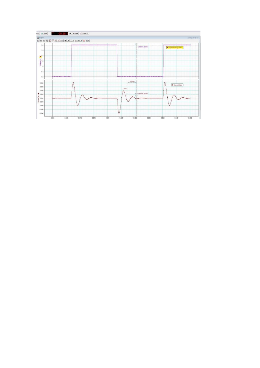
1. Nguyễn Hoàng Minh Phú – CECEIU21027 1. LC Oscillations Theoretical values: Inductance: 0.028 H Capacitance: 10uF
Angular frequency (theory): 1889.82 (rad/s) • Experimental data:
Time at max/min current: 0.0076s
Time at next max/min current: 0.0108s. Time difference: 0.0032s Period: T=0.0032s
Linear frequency: f = 312.5 Hz
Angular frequency (experiment): 1963.49 rad/s
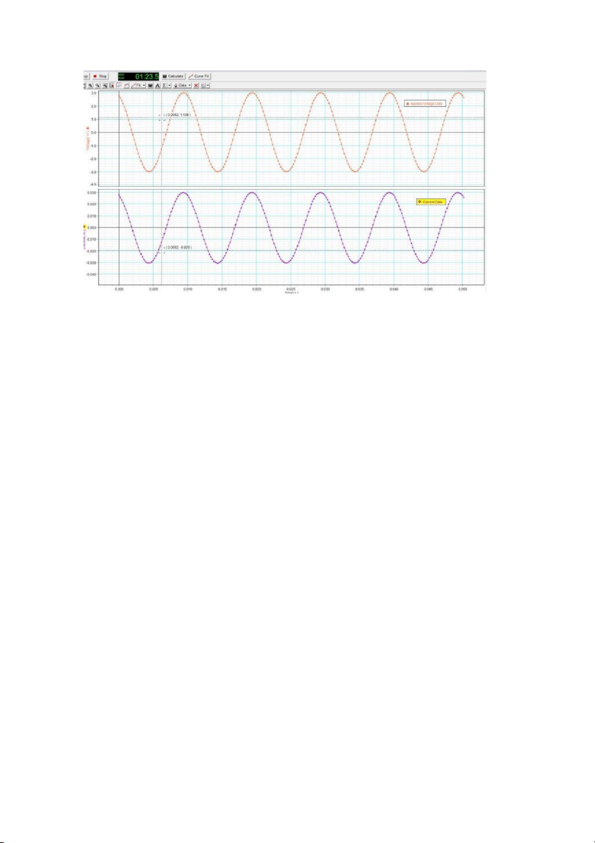
Compare the angular frequencies between theory and experiment: 3.9% 2. Resistive Circuit Resistance: 100 ohm
Period of the AC voltage: 0.01s
Time at max/min current: 0.0122s
Time at max/min voltage: 0.0122s Time difference: 0s Phase difference: 0
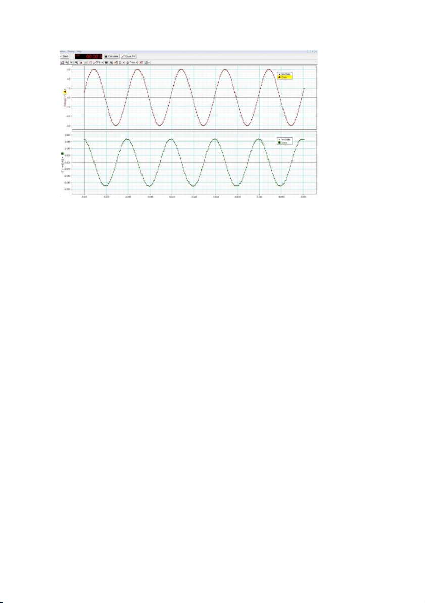
Compare the phase difference with the value predicted by theory: 0% 3. Capacitive Circuit Capacitance: 10 uF
Period of the AC voltage: 0.01 s
Time at max/min current: 0.0096s
Time at max/min voltage :0.0122s Time difference: -0.0026s Phase difference: -93.6
Compare the phase difference with the value predicted by theory: f = 1/0.01 = 100 Hz
f = 1/2π √LC => L = 0.253
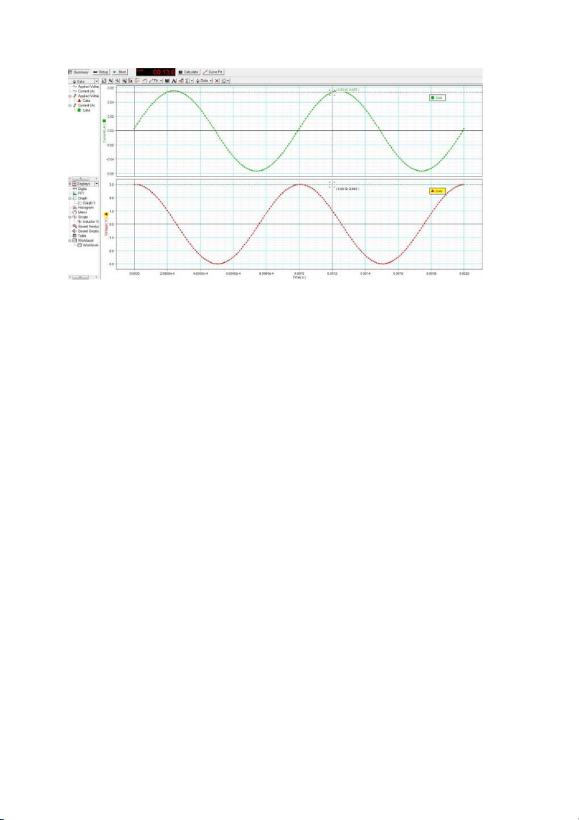
phase difference = arctan(2πfL)=1.565 rad = 89.639 4. Inductive Circuit Inductance: 0.028H
Period of the AC voltage: 0.001s
Time at max/min current: 0.00074s
Time at max/min voltage: 0.00051s Time difference: 0.00023s Phase difference: 82.8
Compare the phase difference with the value predicted by theory:
(frequency f = 1 / T = 1000 Hz)
Phase difference (θ) = arctan(2πfL)
θ = arctan(2π * 1000 * 0.028) θ ≈ 90
Comparing the given phase difference with the theoretical value: 82.8 < 90 radians
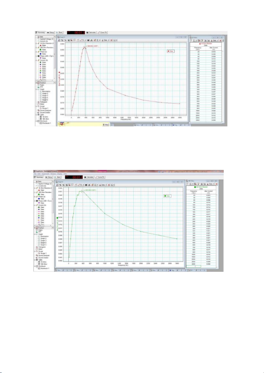
The given phase difference of 82.8 is smaller than the theoretical value of 90. 5. LRC Circuit a. Inductance: 0.028H Resistance: 10 ohm Capacitance: 10uF
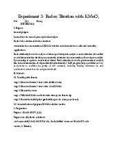
Frequency at which current reaches its max: 380Hz b. Inductance: 0.028H Resistance: 100 ohm Capacitance: 10 uF
Frequency at which current reaches its max: 400H z
Compare the angular frequency in RLC circuit with the one in LC Oscillations. Does the
frequency change when the resistance changes?
The angular frequency for the given RLC circuit: ω = 2π * 380 = 760π ω ≈ 2387.61 rad/s
The angular frequency for the IC oscillations: ω = 2π * 400 = 800π ω ≈ 2513.27 rad/s
The angular frequency changes when the resistance changes in both cases. The value of
resistance affects the behavior of the circuit, including the frequency response.
Does the resistance affect the high of the peak? If yes, show your experimental data and explain.
In RLC circuits, increasing the resistance tends to result in a drop in the peak amplitude of the
current or voltage oscillations. This can be explained by the fact that higher resistance leads to
increased energy dissipation in the circuit, causing the oscillations to have a faster decaying
speed. As a result, the amplitude of the oscillations decreases over time, leading to a lower peak height . Resistance: 10 ohm
Frequency at which current reaches its max: 380Hz Resistance: 100 ohm
Frequency at which current reaches its max: 400Hz
Tài liệu liên quan:
-
Experiment 3: Redox titration with KMnO4 | Bài báo cáo học phần Chemistry Laboratory | Trường Đại học Quốc tế, Đại học Quốc gia Thành phố Hồ Chí Minh
537 269 -
A Report - Laboratory experiment 1 : Chemical reactions | Bài báo cáo học phần Chemistry Laboratory | Trường Đại học Quốc tế, Đại học Quốc gia Thành phố Hồ Chí Minh
625 313 -
A Report - Laboratory experiment 3 : Redox titration | Bài báo cáo học phần Chemistry Laboratory | Trường Đại học Quốc tế, Đại học Quốc gia Thành phố Hồ Chí Minh
361 181 -
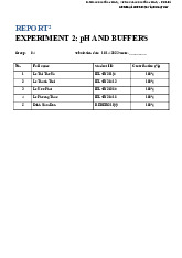
A Report - Laboratory experiment 2 : pH and Buffers | Bài báo cáo học phần Chemistry Laboratory | Trường Đại học Quốc tế, Đại học Quốc gia Thành phố Hồ Chí Minh
555 278 -
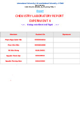
Chemistry laboratory report experiment 4 | Bài báo cáo học phần Chemistry Laboratory | Trường Đại học Quốc tế, Đại học Quốc gia Thành phố Hồ Chí Minh
663 332