Lab 2: Kirchhoff's Current and Voltage Laws | Môn Principles of EE 1 - Trường Đại học Quốc tế, Đại học Quốc gia Thành phố Hồ Chí Minh
Lab 2: Kirchhoff's Current and Voltage Laws Môn Principles of EE 1 .Tài liệu được sưu tầm gồm 8 trang, giúp bạn ôn tập tốt hơn. Mời các bạn đón xem.
Môn: Principles of EE 1 10 tài liệu
Trường: Trường Đại học Quốc tế, Đại học Quốc gia Thành phố Hồ Chí Minh 1.9 K tài liệu
Tác giả:

Preview text:
lOMoAR cPSD| 58097008
INTERNATIONAL UNIVERSITY
SCHOOL OF ELECTRICAL ENGINEERING (EE) EE052 PRINCIPLES OF EE1 LAB LAB 3
Kirchoof’s Current And Voltage Laws
Full name:………………………………..
Student’s ID:……………………….........
Class:……………………………………..
Date:……………………………………... lOMoAR cPSD| 58097008
INTERNATIONAL UNIVERSITY
SCHOOL OF ELECTRICAL ENGINEERING (EE) I. OBJECTIVES
1. To study again the relationship of Ohm's Law.
2. To learn and apply Kirchhoff's Current Law (KCL).
3. To learn and apply Kirchhoff's Voltage Law (KVL).
4. To obtain further practice in electrical measurements.
5. To become more familiar with both series and parallel circuits.
6. To learn how to determine "equivalent resistance" for both series and parallel circuits. II. INTRODUCTION
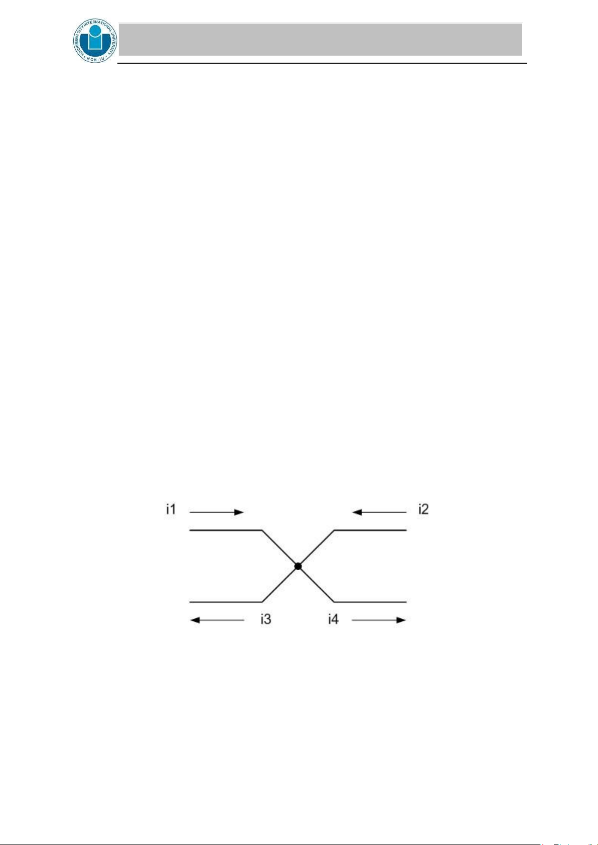
1. Kirchhoff's Current Law (KCL)
KCL states that the algebraic sum of currents leaving any node or the algebraic sum of currents
entering any node is zero, or: i1 + i2 + i3 ...in = 0
Also KCL can be stated as the sum of the currents entering a node must equal the sum of the currents leaving a node, or: i1 + i2 = i3 + i4 Figure 1
As you make a summation of currents, it is suggested that you use currents leaving the node as
positive and the currents entering node as negative, or: -i1 - i2 + i3 + i4 = 0
Kirchhoff's Voltage Law (KVL) states that the algebraic sum of voltages around a closed path is zero, or: lOMoAR cPSD| 58097008
INTERNATIONAL UNIVERSITY
SCHOOL OF ELECTRICAL ENGINEERING (EE) v1 + v2 + v3 ... vn = 0
As you make a summation of voltages, it is suggested that you proceed around the closed path
in a clockwise direction. If you encounter a positive (+) sign as you first enter the circuit
element, then add the value of that. Conversely, if you first encounter a negative sign as you
enter the circuit element, then subtract the value of that voltage.
2. Equivalent resistance
The equivalent resistance of resistors in series is expressed as: Req = R1 + R2 + R3 ... Rn
The equivalent resistance of resistors in parallel is expressed as:
Note: For only two resistors in parallel, the above equation reduces to:
Note also that for resistors of the same value in parallel this reduces to: Req = R1/2 for two resistors
Req = R1/3 for three resistors Req
= R1/4 for four resistors etc.
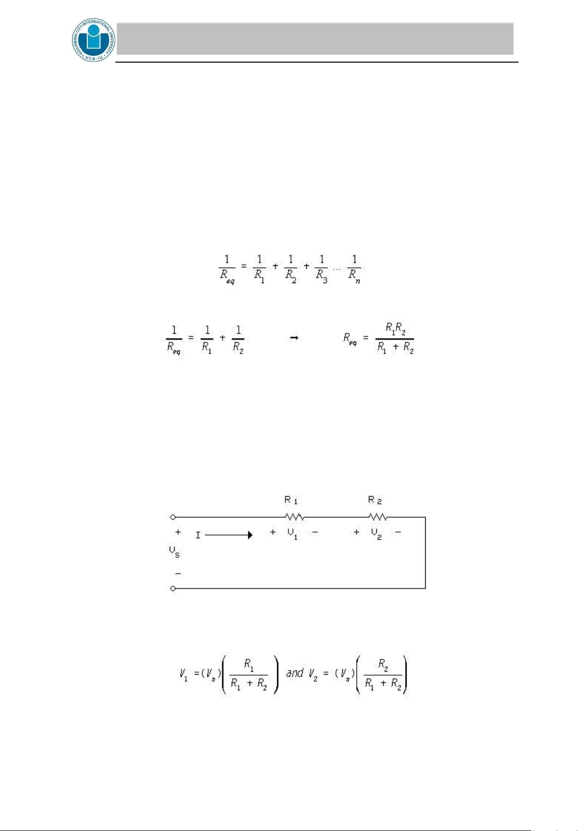
The principle of voltage division can be used for series circuits, and it is stated as follows: The
total voltage across a circuit of resistances in series will divide itself in the circuit in direct proportion the resistances. Figure 2
Using voltage division in the circuit shown in Figure 2:
Also the voltages in Figure 2 can be determined by using Ohm's Law, if you know I. V1 = R1I and V2 = R2I lOMoAR cPSD| 58097008
INTERNATIONAL UNIVERSITY
SCHOOL OF ELECTRICAL ENGINEERING (EE)
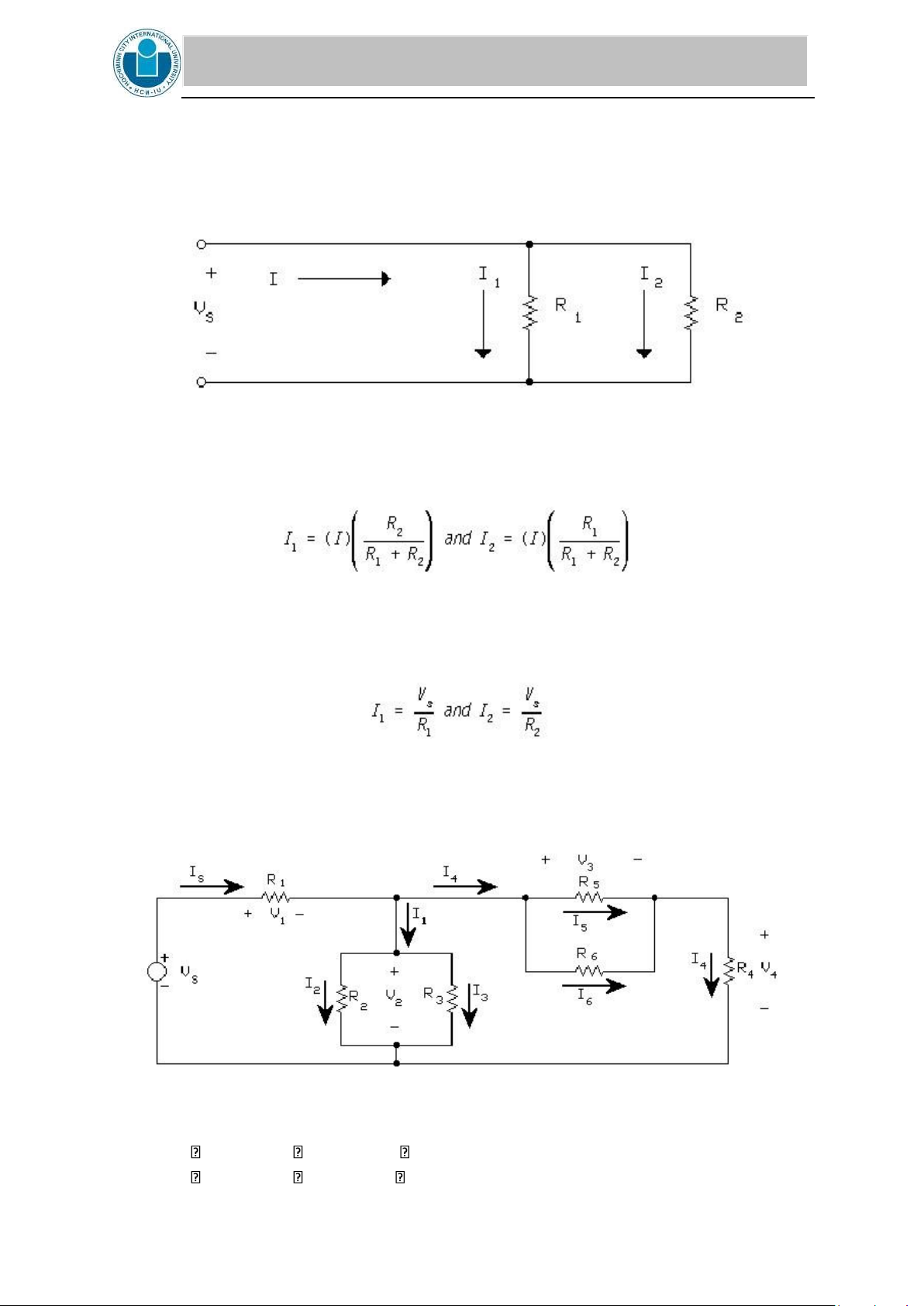
The principle of current division can be used for parallel circuits, and it is stated as follows:
The total current in a circuit of resistances in parallel will divide itself in inverse proportion to
the resistances. Using conductance instead of resistance Where G1 = 1/R1 and G2 = 1/R2 the
currents divide in direct proportion to the conductances. Figure 3
Using current division in the circuit shown in Figure 3:
or I1 = G1/(G1 + G2) and I2 = G2/(G1 + G2)
Also the currents in Fig. 2 can be determined by using Ohm's Law. PRE-LAB
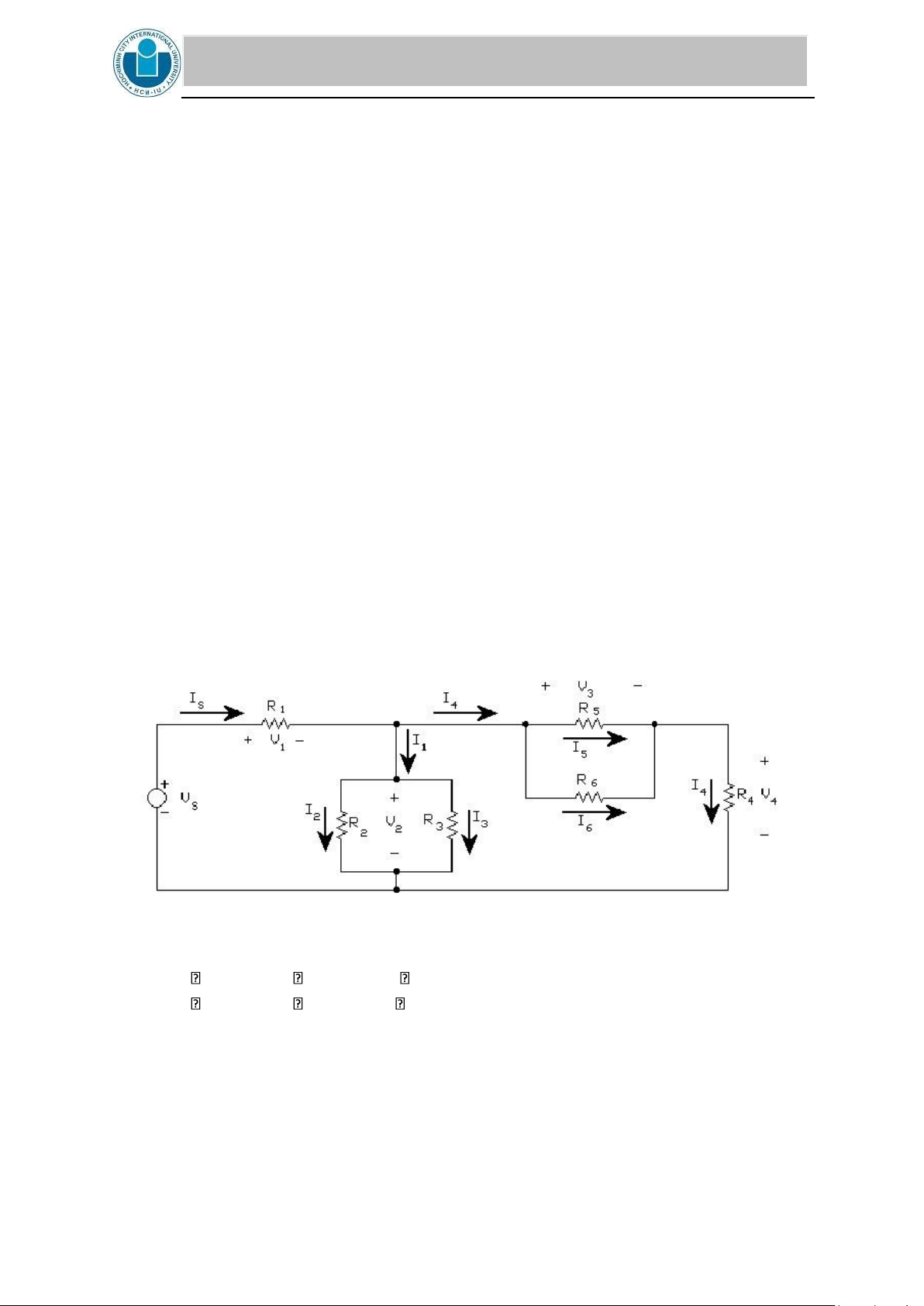
1. Given the circuit 3. Vs is 19V. Calculate Is, I1, I2, I3, I4, I5, I6 CIRCUIT 3
R1 = 1.2 k , R2 = 3.3k , R3 = 3.3 k ,
R4 = 2.7 k , R5 = 5.6 k , R6 = 4.7 k lOMoAR cPSD| 58097008
INTERNATIONAL UNIVERSITY
SCHOOL OF ELECTRICAL ENGINEERING (EE)
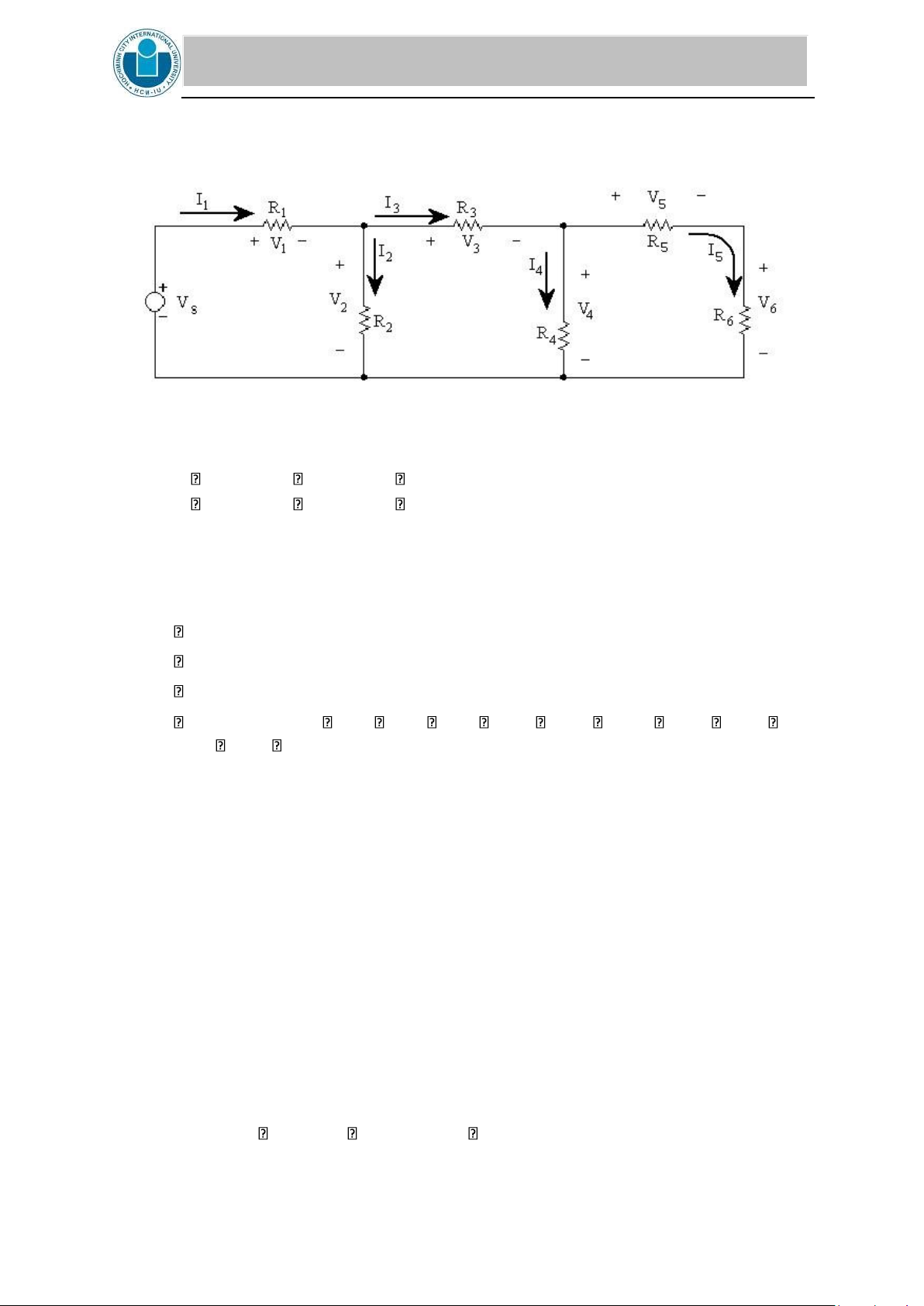
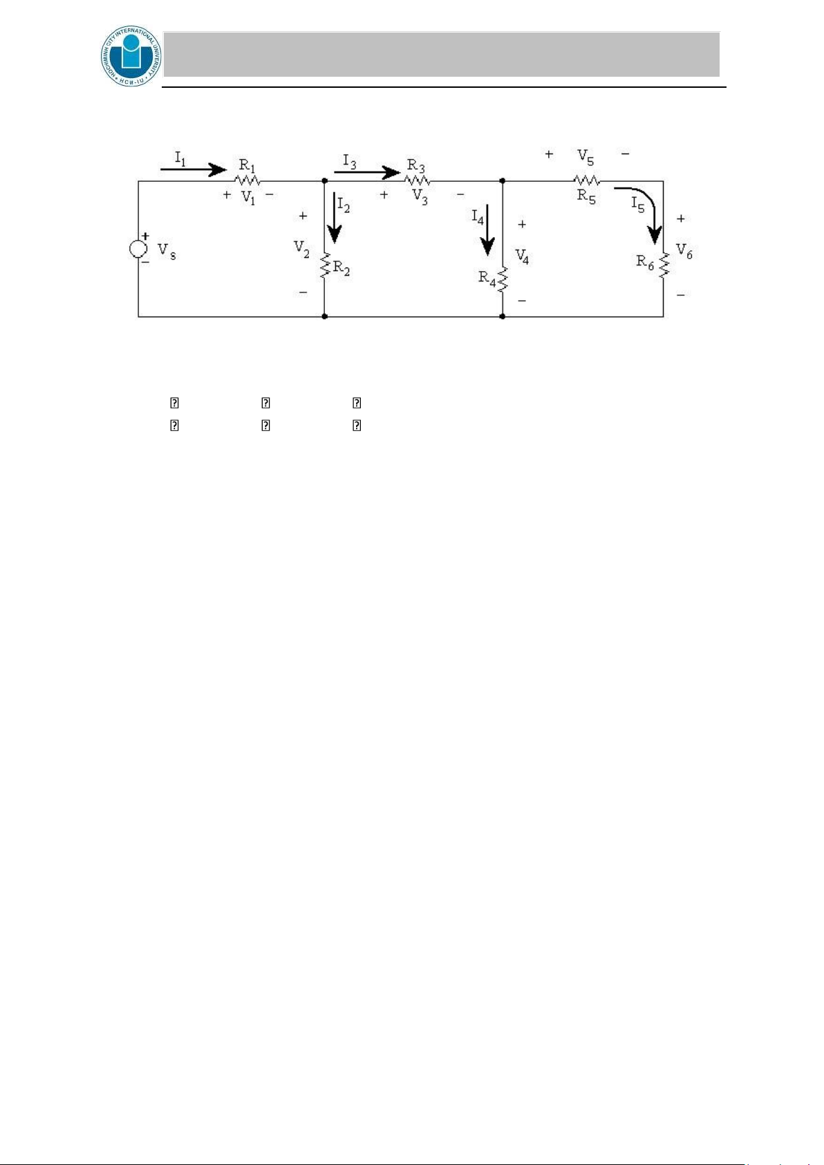
2. Given the circuit 4. Vs is 20V. Calculate I1, I2, I3, I4, I5
Figure 7: CIRCUIT 4
R1 = 1.2 k , R2 = 5.6 k , R3 = 3.3 k ,
R4 = 4.7 k , R5 = 2.7 k , R6 = 1.2 k
III. EQUIPMENT AND PARTS LIST Digital Multimeter (DMM).
Adjustable D.C. power supply . Circuit bread board.
Resistors: 8.2 k , 15 k , 39 k , 820 , 1.5 k , 2.2 k , 1.2 k , 2.7 k , 3.3 k , 4.7 k , 5.6 k IV. PROCEDURES 1. Kirchoff’s Laws
1. Reminder the make, model number, and serial number of each piece of measuring
equipment is required on every experiment.
2. Note the color code on each resistor and match it up with its nominal value from the color
code cards (stuck on the table).
3. Measure and record the actual value for each resistor. Make a tabulation showing nominal
value versus the measured value. Are the measured values within the specified tolerance of the nominal values?
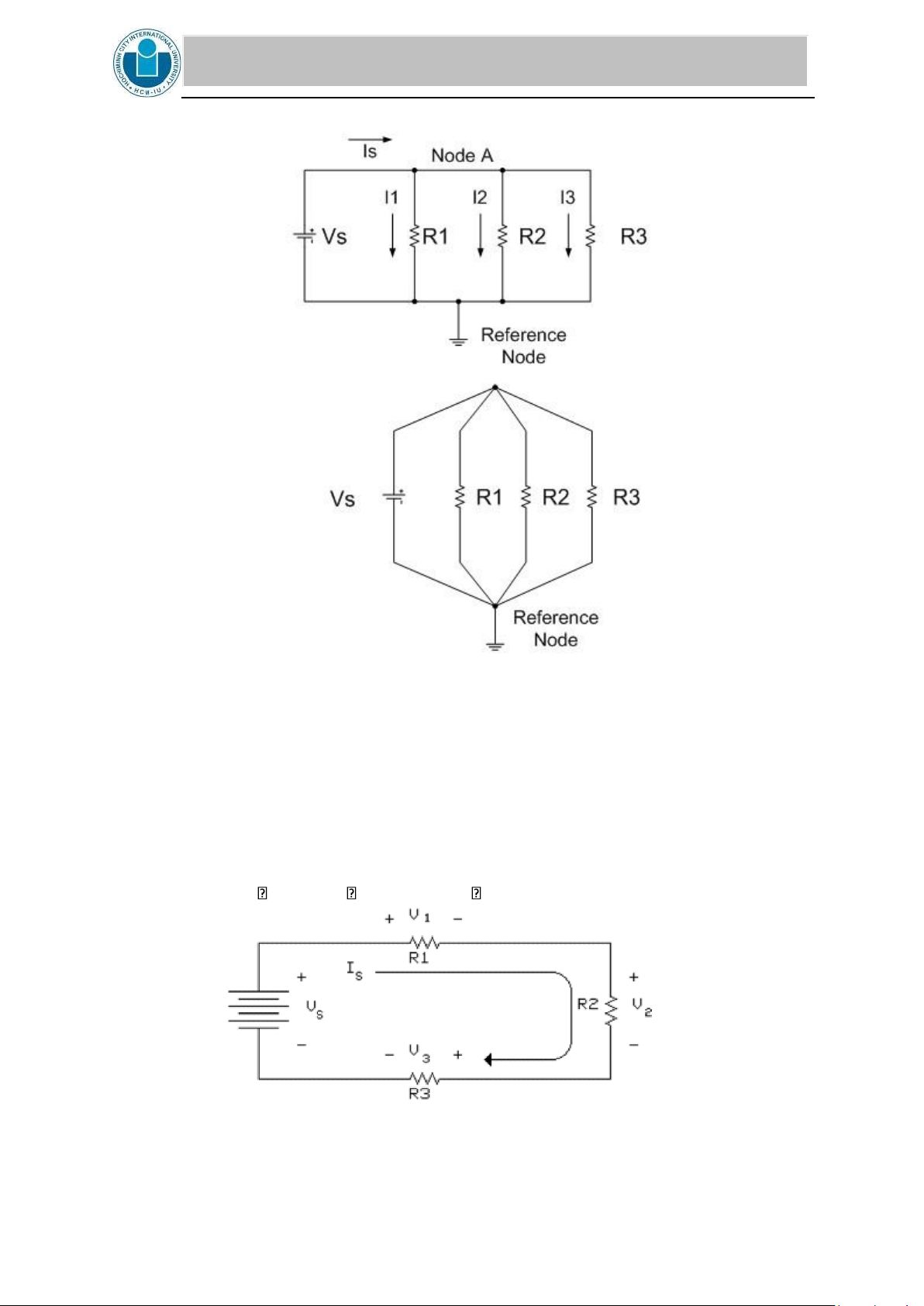
4. Using the adjustable D.C. power supply and circuit bread board, connect the resistors
into a two node circuit as shown below. Note that all four circuit elements are connected
between those two nodes, and the source voltage Vs is across each of the three resistors.
Let R1 = 8.2 k , R2 = 15 k , and R3 = 39 k . lOMoAR cPSD| 58097008
INTERNATIONAL UNIVERSITY
SCHOOL OF ELECTRICAL ENGINEERING (EE)
Figure 4: CIRCUIT 1
5. Measure all four currents, (Is, I1, I2, and I3), in your actual circuit with Vs = 16 V D.C.
Record the actual measured value of the voltage difference between the two nodes.
6. Using the adjustable D.C. power supply and the circuit bread board, connect the resistors
into a circuit as shown below. Note that the three resistors are in series so that the same
current (Is) flows thru each resistor.
Let R1 = 1.5 k , R2 = 820 , and R3 = 2.2 k
Figure 5: CIRCUIT 2 lOMoAR cPSD| 58097008
INTERNATIONAL UNIVERSITY
SCHOOL OF ELECTRICAL ENGINEERING (EE)
7. Set the power supply to Vs = 20 V D.C. measure the all four voltages in your actual circuit. Also measure Is.
CALCULATIONS AND COMPARISONS
1. In Circuit 1, use your measured current values to determine if KCL is verified to within
the limits of the measuring equipment. Also use Ohm's Law and nominal resistance
values to calculate I1, I2, and I3 and then use KCL to calculate Is. Repeat the calculations
using the measured resistance values. Make a chart to compare measured current values
with the two sets of calculated values. Include the % differences in this chart. Are the
differences between the measured values and the values calculated using the measured
resistance values within the accuracy limits of the DMM? Are the differences found using
the nominal values for calculations within the tolerance limits of the resistors?
2. In Circuit 2, use your measured voltage values to determine if KVL is verified is verified
to within the limits of the measuring equipment. Also use measured value of Is, measured
values of resistance, and Ohm's Law to calculate V1, V2, and V3. Make a chart to
compare these calculated voltage values with the measured voltage values. Are all
differences within the expected limits of accuracy?
2. Series-parallel circuit
3. Using the adjustable D.C. power supply and circuit bread board, connect the resistors
into a circuit conforming to Circuit #3 below. Make sure you record the actual value of
each resistor used along with the position in which it was used.
Figure 6: CIRCUIT 3
R1 = 1.2 k , R2 = 3.3k , R3 = 3.3 k ,
R4 = 2.7 k , R5 = 5.6 k , R6 = 4.7 k
4. Measure and record all the currents and voltages in Circuit 3 setting Vs close to 19 V DC.
Measure and record I4 , I5 , & I6 twice.
5. Connect Circuit 4 as shown below. lOMoAR cPSD| 58097008
INTERNATIONAL UNIVERSITY
SCHOOL OF ELECTRICAL ENGINEERING (EE)
Figure 7: CIRCUIT 4
R1 = 1.2 k , R2 = 5.6 k , R3 = 3.3 k ,
R4 = 4.7 k , R5 = 2.7 k , R6 = 1.2 k
6. Measure all the currents and voltages in Circuit #4 setting Vs close to 20 V D.C.
CALCULATIONS AND COMPARISONS:
1. Using methods presented in BACKGROUND AND THEORY plus the attached
reference example, calculate the theoretical values of currents and voltages using the
measured values of resistances and Vs for both Circuit #3 and Circuit #4.
2. Make a table to compare measured values with theoretical values and include the %
difference for each voltage and current.
3. Apply KVL to each loop and KCL to each node. How closely do the voltages and currents
add up to the values predicted? Which current range gave the most accurate values for
I4 , I5 , & I6 in circuit 3?
4. Were Kirchoff's laws verified to within the accuracy of the meter used? Show how you
can demonstrate the overall accuracy of the experiment.
Tài liệu liên quan:
-
Lab 6: Mesh & Nodal Analysis of AC Circuits | Môn Principles of EE 1 - Trường Đại học Quốc tế, Đại học Quốc gia Thành phố Hồ Chí Minh
123 62 -
Lab 4 - Exploring Operational Amplifiers and Their Configurations | Môn Principles of EE 1 - Trường Đại học Quốc tế, Đại học Quốc gia Thành phố Hồ Chí Minh
105 53 -
Lab 7: Operational Amplifiers Study Guide | Môn Principles of EE 1 - Trường Đại học Quốc tế, Đại học Quốc gia Thành phố Hồ Chí Minh
94 47 -
Review Exercises on Laplace Transform & Filter Concepts | Môn Principles of EE 1 - Trường Đại học Quốc tế, Đại học Quốc gia Thành phố Hồ Chí Minh
110 55