Review Exercises on Laplace Transform & Filter Concepts | Môn Principles of EE 1 - Trường Đại học Quốc tế, Đại học Quốc gia Thành phố Hồ Chí Minh
Review Exercises on Laplace Transform & Filter Concepts Môn Principles of EE 1. Tài liệu được sưu tầm gồm 4 trang, giúp bạn ôn tập tốt hơn. Mời các bạn đón xem.
Môn: Principles of EE 1 10 tài liệu
Trường: Trường Đại học Quốc tế, Đại học Quốc gia Thành phố Hồ Chí Minh 2 K tài liệu
Tác giả:
Preview text:
lOMoAR cPSD| 58097008
PRINCIPLES OF EE1 – REVIEW EXERCISES
Laplace Transform exercise:
1. A 500Ω resistor, a 16mH inductor, and a 25nF capacitor are connected in
parallel. The parallel circuit is placed in series with a 2000Ω resistor. Express
the impedance of this series combination as a rational function of s.
(Answer: 2000(s + 50000)2/(s2+80000s+25x 108))
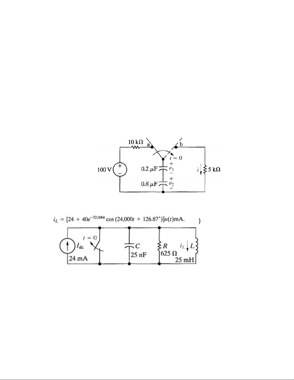
2. The switch in the circuit shown has been in position a for a long time. At t =
0, the switch is thrown to position b.
a) Find I, V1, and V2 as rational functions of s.
b) Find the time-domain expressions for i, v1, v2.
3. The switch opens at t = 0. Find the time-domain expression for iL, given that
the initial energy stored in the circuit is zero. (Answer:
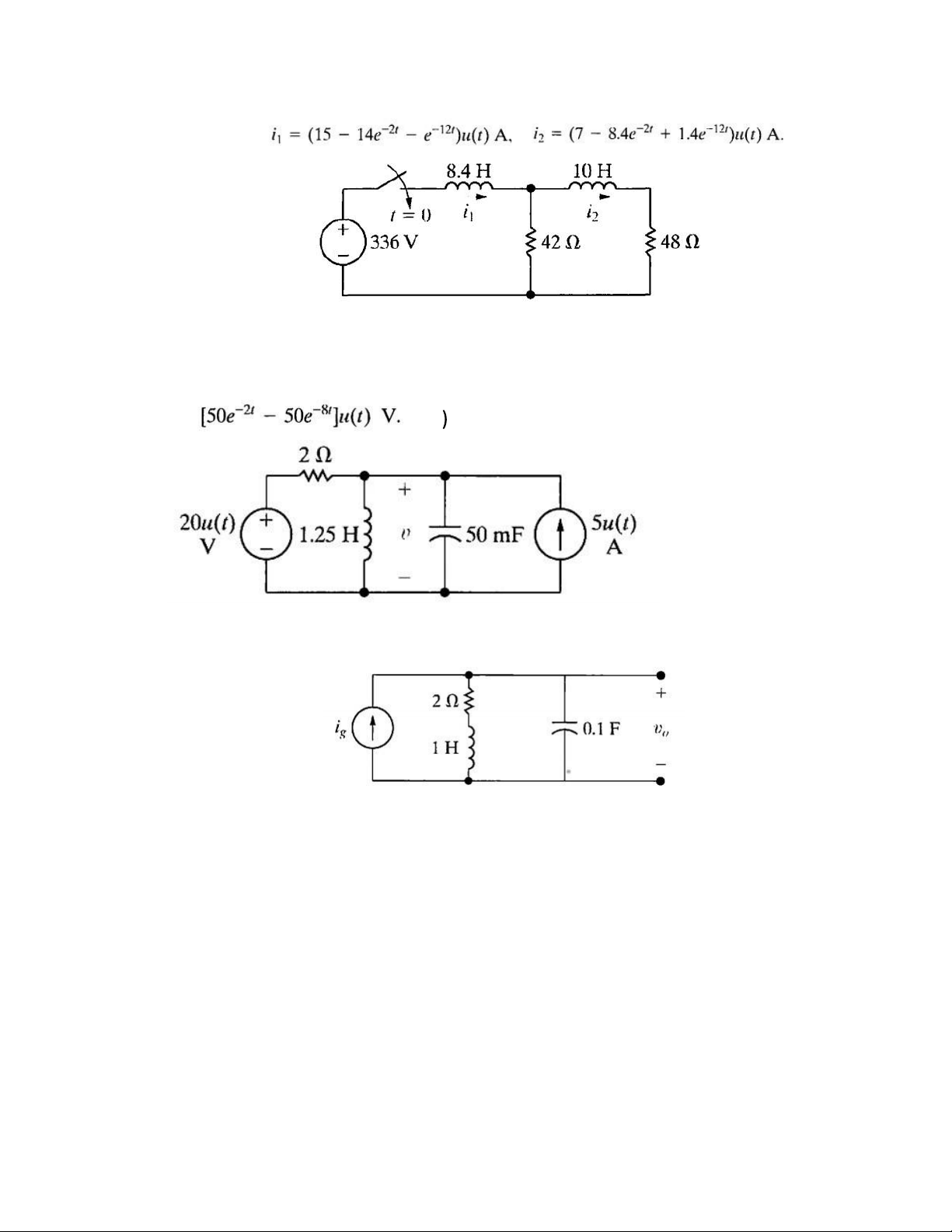
4. The switch closes at t = 0. Find the time-domain expression for i1 and i2
given the initial energy stored in the circuit is zero. lOMoAR cPSD| 58097008 (Answer: )
5. The energy stored in the circuit shown is zero, at the instant the two
sources are turned on. Find the component of v for t>0 owing to the voltage
source, the current source and find the expression for v when t>0. (Ans: v =
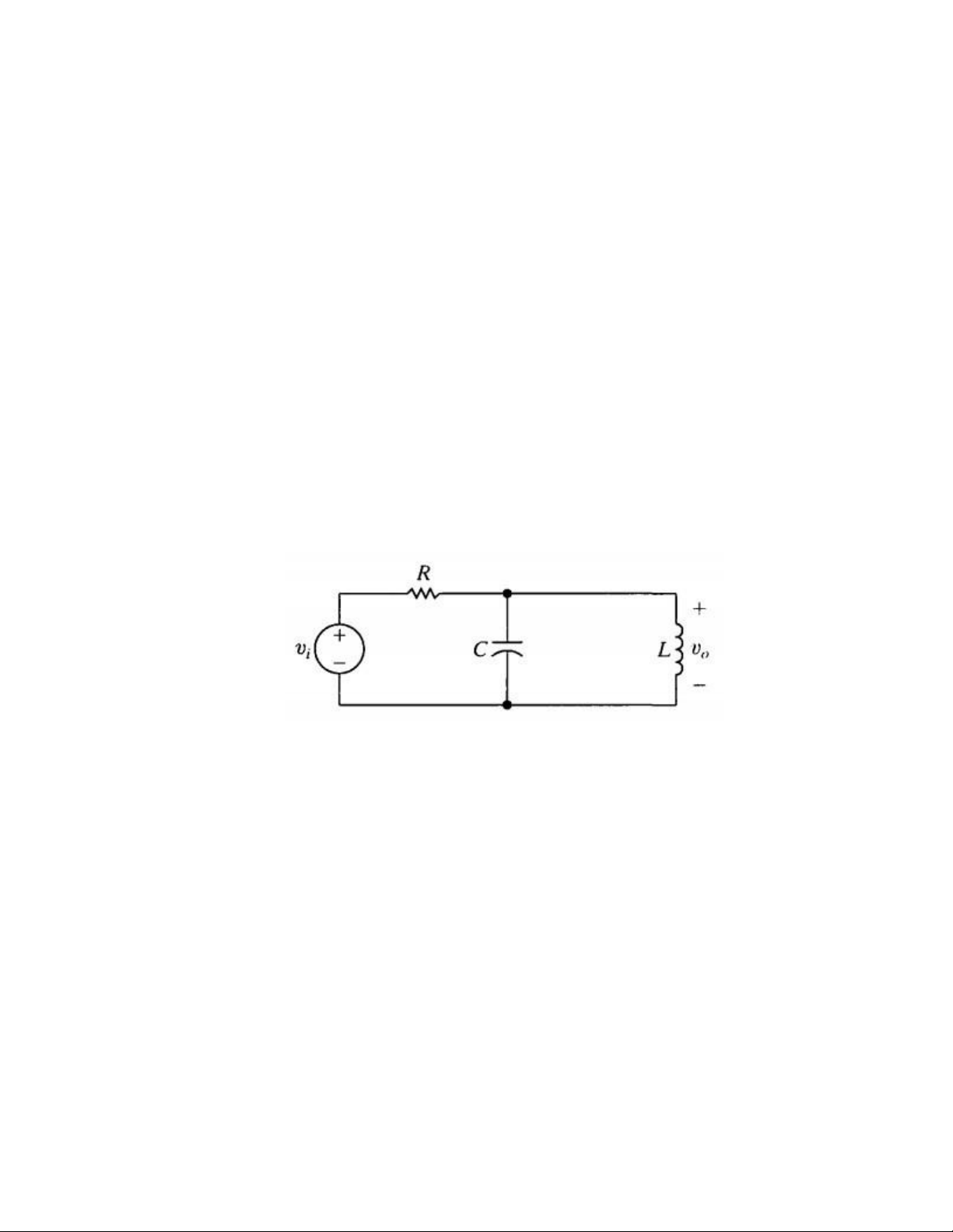
6. Find the transfer function of the circuit below
7. The current source in exercise 6 is delivering 10 cos 4t A. Use the
transfer function to compute the steady state expression for v0.
(Ans: 10 cos 50000t V) Filter exercise:
1. A series RC low-pass filter requires a cutoff frequency of 8 kHz.
Use R = 10 kΩ and compute the value of C required. (Ans: 1.99 nF) lOMoAR cPSD| 58097008
2. A series RL low-pass filter with a cutoff frequency of 2 kHz is
needed. Using R = 5 kΩ, compute L, |H(jω)| at 50 kHz; and θ( jω) at 50 kHz. (Ans: 0.40H, 0.04, -87.71o)
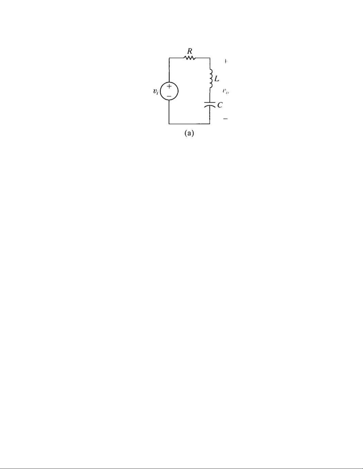
3. Choose values for L that will yield a high-pass filter with a cutoff
frequency of 15 kHz, given that R = 500Ω. Draw the filter and
determine its output. Find the transfer function H(s).
4. A series RC high-pass filter has C = 1 /μF. Compute the cutoff
frequency for the following values of R: (a) 100 Ω; (b) 5 kΩ; and (c) 30 kΩ.
5. Given the bandpass filter in the circuit below. Derive an expression
for the transfer function H(s). Compute the center frequency,
cutoff frequencies, the bandwidth and the quality factor.
6. Using the series RLC circuit below, compute the component values
that yield a band stop filter with a bandwidth of 250 Hz and a
center frequency of 750 Hz. Use a 100 nF capacitor. Compute values for R, L, ω ,ω C1 C2 and Q. lOMoAR cPSD| 58097008
Tài liệu liên quan:
-
Lab 6: Mesh & Nodal Analysis of AC Circuits | Môn Principles of EE 1 - Trường Đại học Quốc tế, Đại học Quốc gia Thành phố Hồ Chí Minh
131 66 -
Lab 4 - Exploring Operational Amplifiers and Their Configurations | Môn Principles of EE 1 - Trường Đại học Quốc tế, Đại học Quốc gia Thành phố Hồ Chí Minh
109 55 -
Lab 2: Kirchhoff's Current and Voltage Laws | Môn Principles of EE 1 - Trường Đại học Quốc tế, Đại học Quốc gia Thành phố Hồ Chí Minh
125 63 -
Lab 7: Operational Amplifiers Study Guide | Môn Principles of EE 1 - Trường Đại học Quốc tế, Đại học Quốc gia Thành phố Hồ Chí Minh
98 49