Tài liệu về Implementing a Direct RF transmitter for wireless communications môn Thu phát vô tuyến | Học viện Công Nghệ Bưu Chính Viễn Thông
Wireless radio transmitters have evolved over the years from real IF (intermediate frequency) transmitters, to complex IF transmitters, to zero-IF transmitters. Tài liệu được sưu tầm gồm 6 trang, giúp các bạn nắm vững kiến thức, rèn luyện kỹ năng và đạt được kết quả tốt trong học tập. Mời các bạn đón xem!
Môn: Thu phát vô tuyến (TEL1416) 10 tài liệu
Trường: Học viện Công Nghệ Bưu Chính Viễn Thông 1.8 K tài liệu
Tác giả:


Preview text:
lOMoAR cPSD| 58977565
Maxim > Design Support > Technical Documents > Application Notes > A/D and D/A Conversion/Sampling Circuits > APP 5317
Maxim > Design Support > Technical Documents > Application Notes > High-Speed Signal Processing > APP 5317
Maxim > Design Support > Technical Documents > Application Notes > Wireless and RF > APP 5317
Keywords: RF, direct RF, RF-to-digital, RF transmitter, direct RF radio transmitter, IF, LO, I and Q, wireless base transceiver
station, BTS, wireless base station, DAC, zero IF APPLICATION NOTE 5317
Implementing a Direct RF Transmitter for Wireless Communications
By: Ajay Kuckreja, Principal Member Technical Staff, Product Definition May 16, 2012
Abstract: The application note summarizes the RF transmitter architectures of zero-IF, complex IF, high (real) IF, and direct
RF before detailing the benefits of the direct RF transmitter for wireless applications, which have increased with the rise in
smartphone and tablet computer use. As the application note shows, the superiority of a direct RF architecture with a high-
performance DAC results in reduced component count and lower power dissipation while synthesizing very wideband signals.
A similar version of this article appears on Wireless Design & Development, March 29, 2012. Introduction
Wireless radio transmitters have evolved over the years from real IF (intermediate
frequency) transmitters, to complex IF transmitters, to zero-IF transmitters. Click here for an overview of the wirelesscomponents used in a typical radio
However, there are stil limitations associated with these commonly used transceiver.
architectures. A newer approach, a direct RF radio transmitter, can overcome the
limitations of traditional transmitters. This article compares various radio transmitter architectures for wireless
communications. The direct RF radio transmitter, enabled by a high-performance digital-to-analog converter (DAC), will
be shown to have clear advantages over the conventional technologies. The direct-to-RF radio transmitter also has its
own challenges, but it paves the way for a true software-defined radio transmitter.
An RF DAC, such as the 14-bit 2.3Gsps MAX5879, is an essential component for the direct-to-RF architecture. This DAC
achieves excel ent spurious and noise performance for bandwidths as wide as 1GHz. It features a novel approach for
transmitting in the second and third Nyquist zones so it can perform RF synthesis at output frequencies as high as 3GHz.
Measurement results verify the DAC's performance.
Traditional RF Transmitter Architectures
Traditional transmitter architectures have been implemented over last few decades based on the super-heterodyne
principle, where an intermediate frequency (IF) is generated using a local oscillator (LO) and a mixer. The mixer typically
creates two images, known as sidebands, around the LO. The wanted signal is then obtained by filtering out one of the
sidebands. Modern radio transmitters, specifically the ones used in wireless base transceiver stations (BTS), commonly
use complex in-phase (I) and quadrature phase (Q) symbols at baseband for a digitally modulated signal. lOMoAR cPSD| 58977565
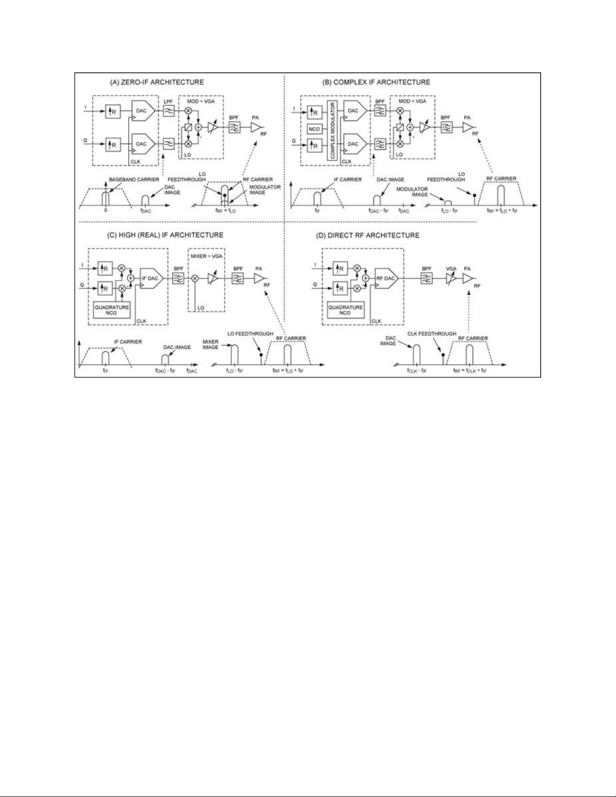
More detailed image (PDF, 80kB) Figure
1. Radio transmitter architectures. Complex IF Transmitter
A complex baseband digital signal thus has two paths at baseband, I and Q. There is an advantage to using two signal
paths in this manner: when the two complex IF signals are combined using an analog quadrature modulator (MOD), one of
the IF sidebands is eliminated. However, because of asymmetries in the I and Q paths, an ideal cancellation of the
modulator image is never achieved. This complex IF architecture is shown in Figure 1(B). Here the complex baseband I
and Q signals are interpolated (by a factor R) and modulated to complex IF carriers using a digital complex modulator and
a numerically controlled oscil ator (NCO) that acts as an LO. The dual DACs then convert the digital I and Q IF carriers to
analog and feed it to the modulator. To further increase attenuation of the undesired sideband, a bandpass filter (BPF) is used. Zero-IF Transmitter
In the Zero IF (ZIF) transmitter shown in Figure 1(A), the digital complex signal at baseband is simply interpolated to ease
filtering requirements and then fed to the DACs. The complex analog output of the DACs, still at baseband (DC), is fed to
an analog quadrature modulator. The "magic" of using complex signals is readily apparent with the ZIF architecture, as the
entire modulated signal is converted to an RF carrier at exactly the LO frequency. However, imperfections such as LO
feedthrough and asymmetries in the I and Q paths result in an LO spur and a reversed signal image that falls within the
transmitted signal. This, in turn, degrades the bit error rate of the signal. In multicarrier transmitters, the images may be
adjacent to the carriers and then in-band spurious emissions result. Complicated digital predistortion schemes are often
implemented in wireless radio transmitters to counter these various imperfections. lOMoAR cPSD| 58977565 Direct RF Transmitter
In the direct RF transmitter shown in Figure 1(D), the quadrature demodulator is implemented in the digital domain and the
LO replaced by an NCO. This results in near-perfect symmetry in the I and Q paths with virtually no LO feedthrough. The
output of the digital modulator is thus a digital RF carrier that is fed to a very high-speed DAC. Since the output of the DAC
is in discrete time, an aliased image is also created equidistant to the DAC clock frequency (CLK). The DAC output is
filtered by the BPF to select the RF carrier and then fed to the variable gain amplifier (VGA). High IF Transmitter
This scheme for the direct RF transmitter can also be used to generate a high, "real" (as opposed to complex) digital IF
carrier, as shown in Figure 1(C). The DAC here converts the digital IF to an analog IF carrier. A bandpass filter that fol ows
the DAC is used to isolate the desired IF image. This real IF is then fed to a mixer which creates two sidebands of that IF
signal mixed with the LO. The desired RF sideband is then isolated by another bandpass filter.
It is apparent that the direct RF architecture requires the fewest active components. Since the analog quadrature
modulator and LO can be implemented in an FPGA or ASIC with a digital quadrature modulator and an NCO, the direct
RF architecture eliminates the I and Q imbalance errors and the LO feedthrough. Moreover, since the DAC is normally
operated at much higher sample rates, it is easier to synthesize very wideband signals while keeping the filtering requirements manageable.
A very high-performance DAC is an essential component for the direct RF architecture to be a feasible alternative to
traditional radio transmitters. This DAC is required to generate RF carriers as high as 2GHz and above, at a dynamic
performance normally achieved at baseband or at an IF using the other architectures. One such high-performance DAC is the MAX5879.
Using the MAX5879 DAC for a Direct RF Transmitter
The MAX5879, a 14-bit 2.3Gsps RF DAC with more than 2GHz of output bandwidth, very low noise, and low spurious
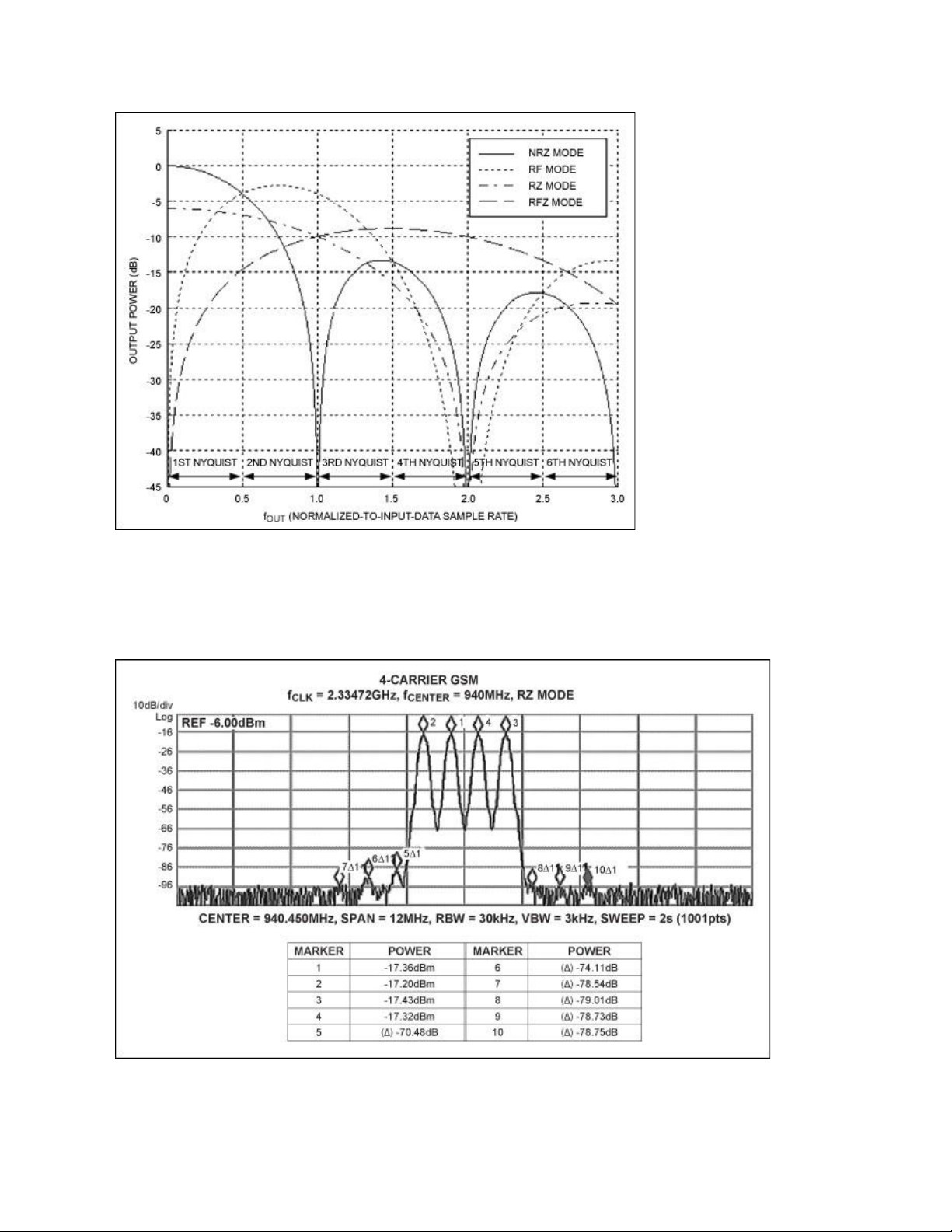
performance, is designed specifically for the direct RF transmitter. Its frequency response (Figure 2) can be modified by
changing its impulse response. The non-return-to-zero (NRZ) mode is used for output in the first Nyquist zone. The radio
frequency (RF) mode concentrates output power in the second and third Nyquist zones. The return-to-zero (RZ) mode
provides a flatter response, but lower output power, across multiple Nyquist zones.
Unique to the MAX5879 is an RFZ mode. The RFZ mode is "zero stuffing" the RF mode, so the input sample rate going into
the DAC is half that compared to the other modes. This mode is useful for synthesizing signals with lower bandwidths while
it retains the advantage of a signal output at much higher frequencies in the upper Nyquist zones. Consequently, the
MAX5879 DAC can be used to synthesize modulated carriers well beyond its sample rate, limited only by the 2+GHz analog output bandwidth. lOMoAR cPSD| 58977565
Figure 2. Selectable frequency response of the MAX5879 DAC.
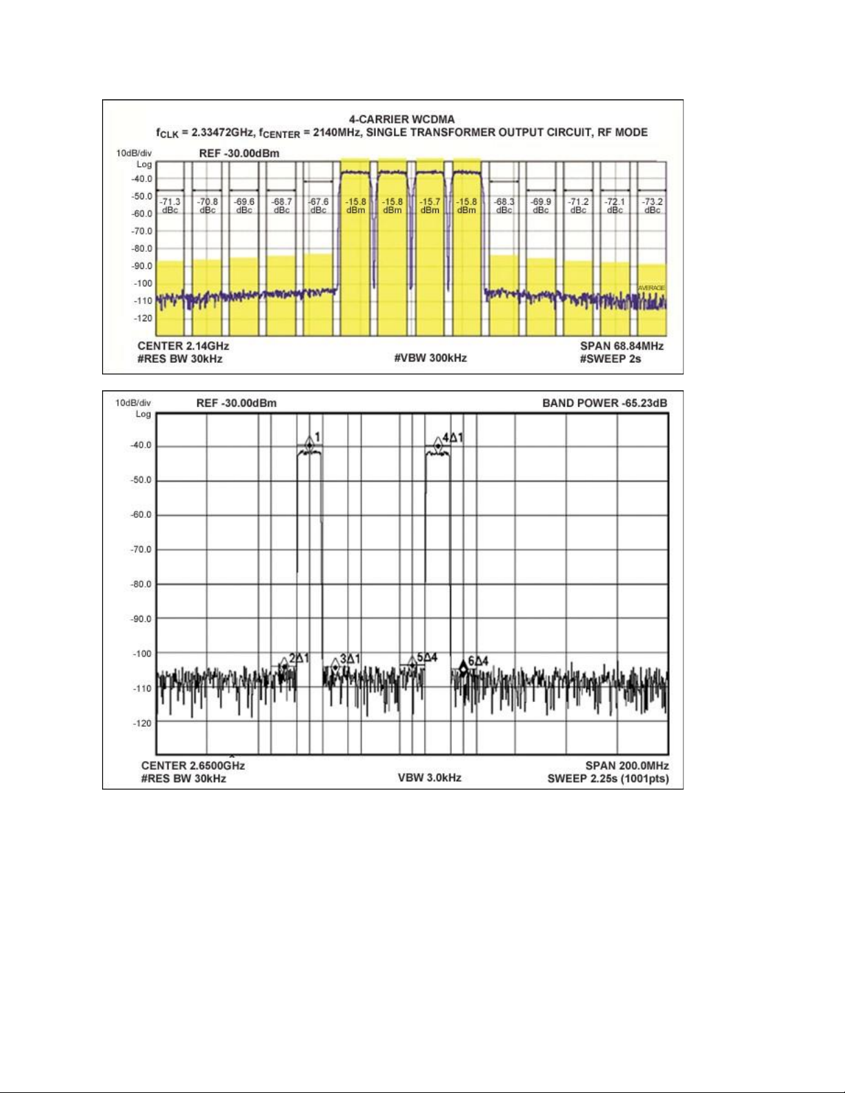
The MAX5879 demonstrates more than 74dB of intermodulation distortion for a 4-carrier GSM signal at 940MHz
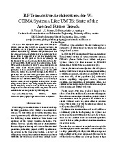
(Figure 3); a 67dB adjacent channel leakage ratio (ACLR) for a 4-carrier WCDMA signal at 2.1GHz (Figure 4); and 65dB
ACLR with a 2-carrier LTE at 2.6GHz (Figure 5). With this performance, this DAC can be used for direct digital synthesis of
a wide variety of digitally modulated signals in multiple Nyquist zones. It thus serves as a common hardware platform for
multistandard and multiband, wireless base-station transmitters.
Figure 3. MAX5879 4-carrier GSM performance at 940MHz and 2.3Gsps (first Nyquist zone). lOMoAR cPSD| 58977565
Figure 4. MAX5879 4-carrier WCDMA performance at 2140MHz and 2.3Gsps (second Nyquist zone).
Figure 5. MAX5879 2-carrier LTE performance at 2650MHz and 2.3Gsps (third Nyquist zone).
Applications for a Direct RF Transmitter
The MAX5879 DAC can also transmit multiple carriers simultaneously within a Nyquist zone. This capability is now
commonly used in downstream cable TV transmitters where multiple QAM modulated signals are transmitted in the 50MHz
to 1000MHz band. For that application the direct RF transmitter can achieve 20 to 30 times the carrier density compared to
the other transmitter architectures. Because, moreover, a single wideband direct RF transmitter can replace multiple radio
transmitters, designs will experience a dramatic reduction both in power dissipation and the area lOMoAR cPSD| 58977565 in the cable TV headend.
The direct RF transmitter using the MAX5879 is also advantageous in many other applications where wide signal
bandwidths and high output frequencies are needed. For example, as more and more smartphones and tablet computers
are utilized, larger bandwidths will be required in wireless base stations. It is thus no surprise that many of the existing
transmitters serving those devices will be replaced by the direct RF transmitter enabled by highperformance RF DACs like the MAX5879. Summary
An RF DAC-enabled transmitter transmits at much higher bandwidths than traditional architectures. It does not compromise
on dynamic performance. It also allows an FPGA or ASIC to eliminate an analog quadrature modulator and an LO
synthesizer, thus increasing the reliability of the radio transmitter. This approach also reduces component count and, in
many cases, lowers power dissipation. More Information
For Technical Support: http://www.maximintegrated.com/support
For Samples: http://www.maximintegrated.com/samples
Other Questions and Comments: http://www.maximintegrated.com/contact
Application Note 5317: http://www.maximintegrated.com/an5317
APPLICATION NOTE 5317, AN5317, AN 5317, APP5317, Appnote5317, Appnote 5317 ©
2013 Maxim Integrated Products, Inc.
Additional Legal Notices: http://www.maximintegrated.com/legal
Tài liệu liên quan:
-

Bài tập quy hoạch mạng hệ thống thu phát vô tuyến môn Thu phát vô tuyến | Học viện Công Nghệ Bưu Chính Viễn Thông
120 60 -
Tài liệu về RF transceiver architectures for W-CDMA systems like UMTS môn Thu phát vô tuyến | Học viện Công Nghệ Bưu Chính Viễn Thông
117 59 -
Tài liệu về Transmit diversity in 3G CDMA systems môn Thu phát vô tuyến | Học viện Công Nghệ Bưu Chính Viễn Thông
118 59 -
Chapter 6 WCDMA môn Thu phát vô tuyến | Học viện Công Nghệ Bưu Chính Viễn Thông
138 69 -
Tài liệu về Introduction to UMTS device testing môn Thu phát vô tuyến | Học viện Công Nghệ Bưu Chính Viễn Thông
119 60