Outline Môn Principles of EE 1 | Trường Đại học Quốc tế, Đại học Quốc gia Thành phố Hồ Chí Minh
Outline Môn Principles of EE 1. Tài liệu được sưu tầm gồm 12 trang, giúp bạn ôn tập tốt hơn. Mời các bạn đón xem.
Môn: Principles of EE 1 10 tài liệu
Trường: Trường Đại học Quốc tế, Đại học Quốc gia Thành phố Hồ Chí Minh 2 K tài liệu
Tác giả:


Preview text:
lOMoAR cPSD| 58097008
International University Principles of EE I School of Electrical Engineering EE052IU
Principles of EE I Laboratory Lab 1 Introduction to
Electric Circuit Laboratory Student A Student B Full name: Full name:
…………………………………
………………………………… Student number: Student number:
…………………………………
………………………………… lOMoAR cPSD| 58097008
International University Principles of EE I School of Electrical Engineering EE052IU 1. Objectives
In this laboratory, you will be introduced:
• Lab policies & Lab Safety Rules. • The use of breadboard.
• Resistor color codes and capacitor codes.
• The equipment will be used during this laboratory.
2. Introduction to Electric Circuit Laboratory
a. Lab policies & Lab Safety Rules
i. Important Notes: Read carefully the following points:
• The students should be prepared on the theoretical material of the lab topic.
• Be prepared to answer questions.
• The students should prepare previously all Pre-Lab calculations and simulations.
• The presentation of a previous year's or someone else's lab is considered cheating.
• The students need to follow SEE’ official lab report template to write a PDF report for each lab.
ii. Instruments and supplies
The major instruments you will need are permanently installed in the stations. A selection of wires,
cables and connectors are inside your kit. Small parts (resistors, capacitors, transistors, ICs) will
be available in the bins in the lab area. They can be reused and should be left on the table in the
same manner as they were obtained.
iii. Leave your workplace at least as clean and tidy as you found it.
Put everything back in its proper place. If the workplace is not tidy after you finish, it will cause to lose some points. iv. Precautions
Electronic test equipment can be damaged if incorrectly used.
• The function generator will be damaged if a large DC or AC voltage is applied to the outputs.
• The oscilloscope also has input limitations. Do not exceed 300V on any oscilloscope input. lOMoAR cPSD| 58097008
International University Principles of EE I School of Electrical Engineering EE052IU
• Power supplies can also be damaged if an external voltage in excess of the supply output
voltage is fed back into the supply.
• The most common ways multi-meters are damaged are by trying to measure voltage when
the meter is set to measure current or resistance or by exceeding the maximum voltage
when in the voltage measurement mode. Think twice before connecting a meter. In
particular, check the position of the function switch and ensure the test leads are
connected to the proper inputs on the meter. If you make a mistake, you could blow the
meter’s internal fuse or damage the converter chip.
v. No foods or drinks are allowed inside the lab for any reason.
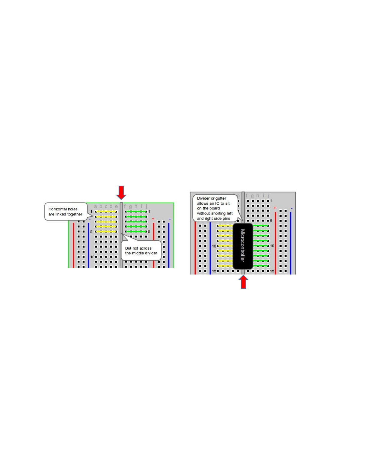
b. The use of breadboard. i. Horizontal Rows
You can see that the horizontal rows are connected on the inside.
When you put your IC chip on board it should hurdle the center divider. You can see from
diagram that the pins of the IC are now accessible by inserting a component or jumper wire in
the available horizontal pins and connecting to another row. ii. Vertical Columns
Vertical columns on the side of the breadboard are for power and ground. lOMoAR cPSD| 58097008
International University Principles of EE I School of Electrical Engineering EE052IU
These power rails are also isolated to the right and left side of the breadboard.
If you have to manage two different power supplies or voltages, they can be isolated by keeping
them on either side of the board.
c. Resistor color codes and capacitor codes.
i. Resistor color codes
Figure 1 Resistor color codes ii. Capacitor codes lOMoAR cPSD| 58097008
International University Principles of EE I School of Electrical Engineering EE052IU
Figure 2 Capacitor codes
d. The equipment will be used during this laboratory.
Figure 3 Basic set of equipment lOMoAR cPSD| 58097008
International University Principles of EE I School of Electrical Engineering EE052IU Light
i. Power Supply signals Output control Three control modes Two adjustable VDC sources Figure 4 Power supply
Steps on how to use the Power supply: One fixed • Turn on the device 5 V VDC source
• Turn all the Voltage & Current turners to zero (your left); the Light signal should be Red.
• Hook up your power supply to your circuit(s) (Red for Hotwire, Black for Ground)
• Turn the Voltage turner to the desirable voltage; slowly turn the Current turner up
until the Light Signal turn Green.
• Hit the Output control button. (If the Light signal turn Red again, hit the Output
control button again to turn off & check your circuit; it is likely to be short- circuited)
• After you done with your lab, turn off the device, return all the cables to their original places.
*About the three control modes, you mostly will only use INDEP. Or Independent mode
which will separate the two adjustable sources. In the likely event that requires +15/-15
voltage supply for IC chip, request the assistance from your instructor unless you are
certain of what you are doing.
ii. Digital Multi-Meter lOMoAR cPSD| 58097008
International University Principles of EE I School of Electrical Engineering EE052IU Control modes Parameter settings
Figure 5 Digital Multi-Meter Plugins
* Do not measure the components when they are still attached to the circuit; your
measurements will likely be incorrect.
iii. Function Generator Plugins Parameter settings Control modes
Figure 6 Function Generator iv. Oscilloscope lOMoAR cPSD| 58097008
International University Principles of EE I School of Electrical Engineering EE052IU Control modes Parameter settings Figure 7 Oscilloscope Plugins Scaling settings
*How to read the oscilloscope:
All oscilloscopes have some basic controls in common, be sure you can identify these controls on your oscilloscope:
• at least one input where an oscilloscope probe (also called a coaxial cable) can be
attached (be sure you have one of these cables)
• screen with a grid overlay- this grid is useful when you want to make measurements using the scope
• volts/div- this control lets you change how many volts are represented by each vertical
increment of grid overlay on the screen. Basically, it allows you to zoom in and out along the y axis.
• time/div- this control lets you change how much time is represented by each horizontal
increment of the grid overlay on the screen. It allows you to zoom in and out along the x axis.
• vertical position/offset- lets you move up and down in the y direction
• horizontal position/offset- move left and right
• trigger level- this is a tool that allows you to stabilize your waveform on the screen
Turn on your oscilloscope. If nothing is plugged into the oscilloscope you should to see a flat
line, this means that the voltage of the input is not changing over time. If you see a line that is
not flat, try disconnecting the probe from the oscilloscope. If the screen is blank try the
following (remember all oscilloscopes are a little different, don't worry about pressing buttons if
you're not sure, you won't break anything): lOMoAR cPSD| 58097008
International University Principles of EE I School of Electrical Engineering EE052IU
• my oscilloscope is a dual channel scope which means it has two inputs. As shown in
figure 2, pressing the "channel 1" button causes that input to display on the screen in
yellow. Pressing it again will cause it to disappear. Pressing channel 2 will display that
input in blue. Your oscilloscope may only have one input (no channel buttons), or it may
have more than 2. Analog scopes will not display separate channels as different colors, it's all green.
• you may be zoomed in tight on some blank space, try turning the volts/div knob
counterclockwise to zoom out, also try turning the vertical position control until you get a
flat line centered in your screen.
• make sure you scope is not in x y mode
Figure 8 Oscilloscope How to 1 I
used the following parameters: • Volts/div = 1V • Time/div = 1ms
Adjust vertical position until wave oscillates around the center of the screen. lOMoAR cPSD| 58097008
International University Principles of EE I School of Electrical Engineering EE052IU
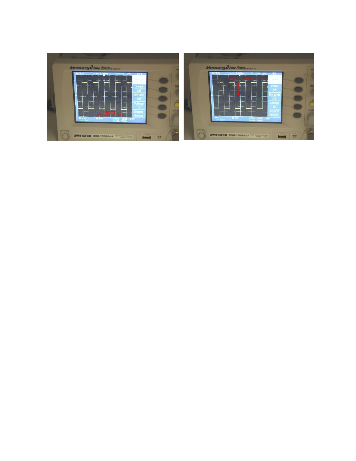
Figure 9 Oscilloscope : Time/div reading
Figure 10 Oscilloscope : Volts/div reading
*If you need anything, give me a holler. lOMoAR cPSD| 58097008
International University Principles of EE I School of Electrical Engineering EE052IU 3. Lab procedures Student A Student B
a. Reading the Resistors 150 ohm, 5% = 56K ohm, 5% = 270 ohm, 5% = 1K ohm, 5% = 3300 ohm, 5% = 1M ohm, 5% =
470 ohm, 2% = 100.000 ohm, 5% = 3K3 ohm, 5% = 390 ohm, 5% = 1 ohm, 1% = 3300 ohm, 2% = 1200 ohm, 5% = 3M9 ohm, 10% = 220 ohm, 1% = 47 ohm, 5% =
3900 ohm, 2% = 10K ohm, 5% = _
10.000 ohm, 5% = 1500 ohm, 2% = 470K ohm, 1% 2K76 ohm, 1% = 1.8 ohm, 2% = 2.2 ohm, 1% =
11K2 ohm, 5% = 94.1K ohm, 2% =
6800 ohm, 10% = 10M ohm, 10% = 1M ohm, 10% = 2M9 ohm, 10% =
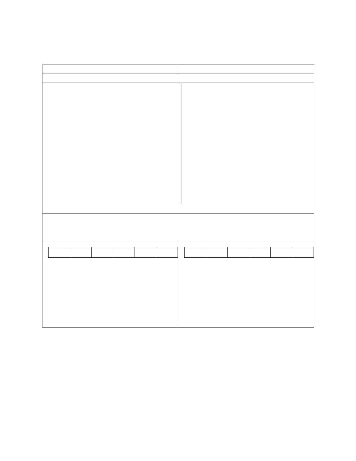
b. Measure the Resistor values
Each student goes to the counter and pick 5 resistors with the same color code (two students in
the same team should not pick the same color code resistor) and fill the tables below. The color band The color band
The value of Resistor is :_________________ The value of Resistor is :________________
The actual value of the 1st resistor:_________ The actual value of the 1st resistor:_________
The actual value of the 2nd resistor:_________ The actual value of the 2nd resistor:_________
The actual value of the 3rd resistor:_________ The actual value of the 3rd resistor:_________
The actual value of the 4th resistor:_________ The actual value of the 4th resistor:_________
The actual value of the 5th resistor:_________ The actual value of the 5th resistor:_________ lOMoAR cPSD| 58097008
International University Principles of EE I School of Electrical Engineering EE052IU
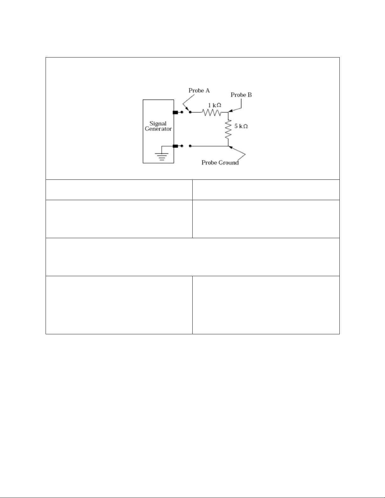
c. Measure Voltage Differences
Build the simple circuit shown, Vi = 5sin(2π1000t) (V), then measure the amplitude of the signals at A and B with respect to ground.
• Open the simulation platform of your choice • Take the breadboard and the components
and perform the Transient Analysis,
from the counter, put together the circuit
only show the first three periods of both
and use the Function generator to power up signals A & B.
your circuit as well as use the Digital
Oscilloscope to draw first three periods of both signals A & B.
d. Frequency and Phase Shift Measurement
Replace the 1kΩ resistor with a 330Ω and the 5kΩ resistor with a 1µF capacitor, change the
input frequency to 500Hz only. Then measure the amplitude of the signals at A and B with
respect to ground. (Hint : Signal B should be lagging with an angle of 46o with respect to A.)
• Take the breadboard and the components • Open the simulation platform of your choice
from the counter, put together the circuit
and perform the Transient Analysis, only
and use the Function generator to power up
show the first three periods of both signals
your circuit as well as use the Digital A & B.
Oscilloscope to draw first three periods of both signals A & B.
Tài liệu liên quan:
-
Lab 6: Mesh & Nodal Analysis of AC Circuits | Môn Principles of EE 1 - Trường Đại học Quốc tế, Đại học Quốc gia Thành phố Hồ Chí Minh
132 66 -
Lab 4 - Exploring Operational Amplifiers and Their Configurations | Môn Principles of EE 1 - Trường Đại học Quốc tế, Đại học Quốc gia Thành phố Hồ Chí Minh
109 55 -
Lab 2: Kirchhoff's Current and Voltage Laws | Môn Principles of EE 1 - Trường Đại học Quốc tế, Đại học Quốc gia Thành phố Hồ Chí Minh
125 63 -
Lab 7: Operational Amplifiers Study Guide | Môn Principles of EE 1 - Trường Đại học Quốc tế, Đại học Quốc gia Thành phố Hồ Chí Minh
99 50 -
Review Exercises on Laplace Transform & Filter Concepts | Môn Principles of EE 1 - Trường Đại học Quốc tế, Đại học Quốc gia Thành phố Hồ Chí Minh
115 58